PCB Prototype the Easy Way
Full feature custom PCB prototype service.
9:00 - 18:00, Mon.- Fri. (GMT+8)
9:00 - 12:00, Sat. (GMT+8)
(Except Chinese public holidays)
1. The technical team consists of dozens of engineers who have more than 10 years of FPC processing experience. New equipment are introduced in millions of dollars yearly to continuously improve the process manufacturing capability.
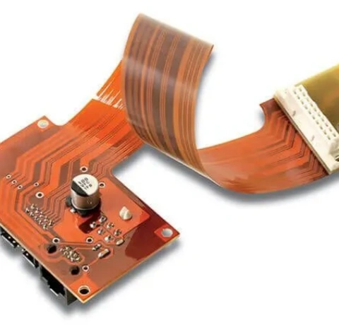
2. The highest 16-layer Rigid-flex PCB processing technology, the minimum trace and space is 2/2mil, the minimum via is 4mil.
3. Rich experience in manufacturing FPC products for medical and consumer electronics.
1. UL certification.
2. ISO9001:2008 quality certification.
3. ISO/TS1694:2009 certification.
4. Strictly manage the processing of customized products according to IPC6012 II /III/customer standard/enterprise internal standard.
5. Strict management for customer information confidentiality.
Item | Position | Standard |
Identification | Entire board | Graphics, markings and plating pressures are in accordance with the customer’s request or IPC-600H. |
Plated hole | Entire board | The plated holes should be clean and free of any impurities that affect component insertion and solderability. The total area of the voids should not exceed 10% of the total area. The horizontal and vertical dimensions of the voids should be less than 25% of the total length. |
Board edge | Entire board | The edge of the board and the internal cuts should be neat and there should be no tears or gaps. |
Bonding of the circuit to the substrate | Entire board | The circuits should not be separated from the substrate by significant blistering or wrinkles. |
Adhesion of the cover layer to the substrate and graphics | Entire board | At random locations away from the conductor, the area of each layer shall not exceed 5 mm2 and distance shall be bigger than 0.5 mm from the edge of the panel. Along the edge of the conductor, it shall be visually no bigger than 20% of the design spacing. |
Particles between circuits | Entire board | Residual metal particles are allowed to be reduced by not exceeding 20% or not less than the circuit voltage requirement. |
Conductor defect | Entire board | There should be no cracks or breaks, and the conductor reduction should not exceed 20% of the total width of the conductor. |
Size | Entire board | All dimensions and tolerances should be in accordance with customer requirements. |
Clearance hole | Entire board | The polymerization of holes including adhesive flow on the pads should be less than 0.1 mm. |
Pad | Entire board | The pad should not be broken and there should be no breaks at the junction of the pad and the circuits. |
Rigid and Flex joint | Entire board | The connection between the flexible part and the rigid part shall be complete and uniform. At the rigid and flexible joints, the flow of resin to the joint between the rigid and flex joint shall not exceed 2 mm. |
Insulation resistance | Insulation resistance should be tested before and after environmental treatment and should meet customer requirements. | |
Peel strength | Circuit to substrate | Should meet the requirements of rigid boards. |
Pull strength of pad | The pads should not be separated during the soldering, and the pull strength should be less than the requirements of the supplier and the purchaser. The flexible part requires rigid board to support. | |
Plating adhesion | Entire board | When the tape is pulled down from the conductor, there should be no trace of plating adhesion. |
Solderability | Entire board | The conductor should be covered by a smooth, shiny solder layer, for example, pinholes, non-wetting, semi-wetting, etc. should not exceed 5%. |
Thermal shock | Entire board | The plating layer and circuits should be free of cracks, blistering or delamination. |
1.Orbotech AOI (automatic optical inspection) machine imported from Israel for detecting high-precision circuits.
2.The high-precision impedance tester imported from the United States meets the impedance test requirement.
3. PLASMA plasma processing equipment, used for hole wall degumming of PTFE, ceramic fillers and other high-frequency material.
4. Ende CNC drilling machine imported from Taiwan for back drilling and deep hole control.
5. Orbotech LDI machine (laser direct imaging) imported from Israel for graphic transfer of high-precision circuits.
6. Ende CNC numerical control molding machine imported from Taiwan, used for deep-groove milling of stepped groove structure products.
7. BURKLE lamination imported from Germany for multi-layer boards pressing.
8. Vacuum resin plugging machine for hole plug in BGA panel of ultra high-precision circuits.
9. Quick press machine for FPC cover film pressing.
10. Ion staining tester, anti-stripping strength tester, hole copper tester, secondary element tester, copper thickness tester and other reliability testing equipment to ensure product quality.
1. PCB and FPC substrate materials: Select the top brands in the industry: Shengyi, ROGERS, ARLON, 3M, Dupont, etc.
2. Auxiliary materials: Rohm and Haas electroplating syrup, Hitachi dry film, Taiyo ink, Noda resin, etc.
1. Efficient service
1 minute to respond to customers, 1H to reply results, 1 day to solve problems, 1 week to complete service.
2. Fast delivery (work day,China Time Zone(GMT+8))
Layers | Build Time(H:hours) |
2 Layers | 24H+1days |
4 Layers | 48H+1days |
6-8 Layers | 72H+1days |
10-16 Layers | 96H+1days |
The highest 16-layer Rigid-flex PCB processing technology
Surface Finish: ENIG + Silver Paste, Structure:1+2F+1
Surface Finish:Immersion gold, Structure:1+2F+1
4 layered HDI with Buried holes, Structure:1-{(2)}-1
0.6mm total thickness, Structure:1-2F-1
2 layers, Material: PI, silver film, Thickness: 0.1mm
7 layers, Material: PI, FR-4, Thickness: 0.45mm
4 layers, Material: PI, FR-4, Thickness: 1.6mm
10 layers, Material: PI, FR-4, Grosor: 2.0mm
12 layers, Material: PI, FR-4, Thickness: 1.6mm
4 layers, Material: PI, Thickness: 0.2mm
4 layers, Material: PI, Thickness: 0.8mm
Contact Us!
Our customer service+86-571-85317532
I ordered the PCB just last week, and it arrived in only six days—much faster than I expected. The production process was without any problems, and there were absolutely no issues during manufacturing or delivery. The quality of the board looks excellent, and it matches my design perfectly. This PCB will be invaluable for confirming all the details before committing to the full production run. I'm genuinely impressed with the speed and reliability of the service, and I’m excited to start working with it to validate my project. This quick turnaround has saved me a lot of time and effort in my development process.
Ullrich
Perfect work as always, thanks for bringing the project to life.
Gzowski