100W Lab Bench Power Supply From a Fast Charger
Power supplies play a very important role in testing electronic circuits. Power supplies are used to get a constant voltage or constant current out of them. Most modern power supplies come with a lot of features, such as temperature monitoring, constant current and constant voltage mode. We can set a desirable range of potential and current by adjusting the potentiometer knob. But these power supplies cost a lot and are very bulky in nature. On the other hand in basic to advanced electronics most of the circuit works at voltage less than 20V. That’s why I am in search of a power supply module, which can deliver power in this range. And to get rid of this bulky power supply, I found the best method to be USB power delivery.
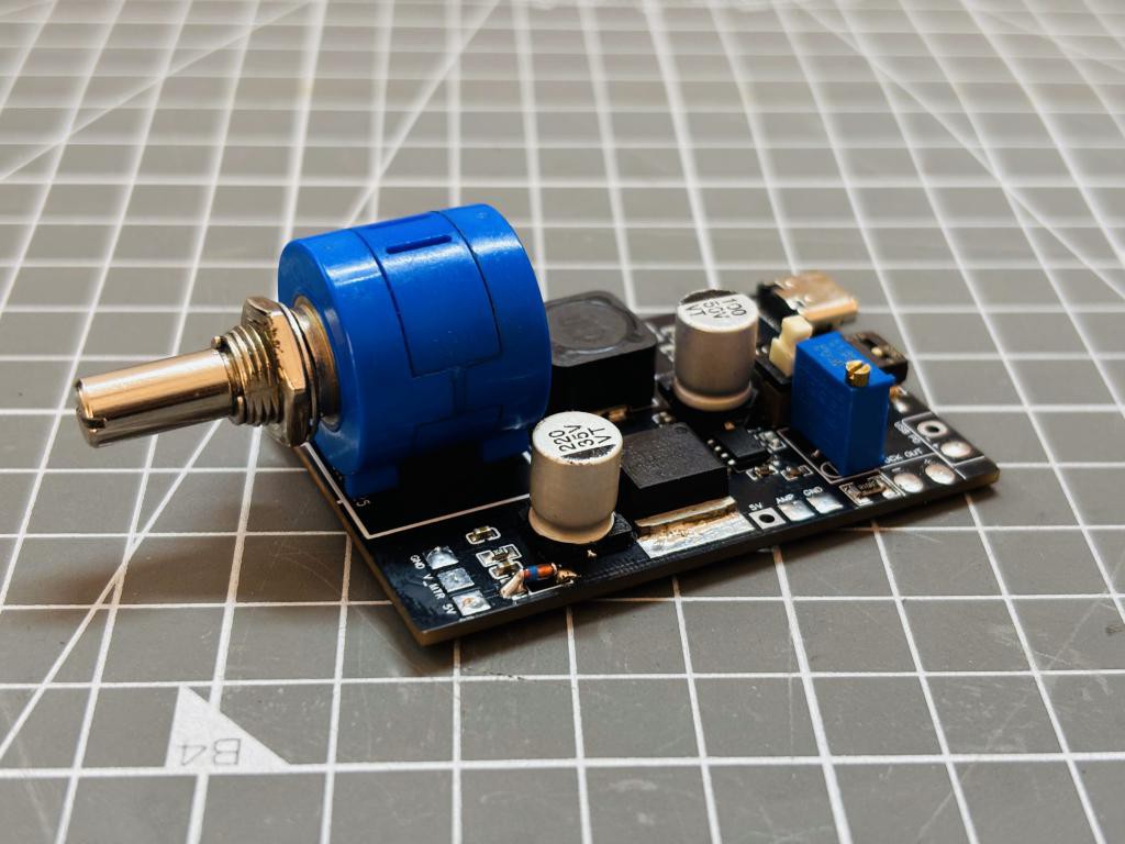
With USB-C chargers, now we can get different voltages which helps to fast charge the batteries. Lithium polymer batteries inside the mobile
phone can now be charged with higher current to implement fast charging. All this happens with a buck converter circuit at the battery interface. But it is not easy to get a desirable output from a USB-C fast charger.
All this depends upon the interfacing circuit we are using. The best method to use a dedicated power delivery IC, I found the CH224k is a single-chip solution that integrates USB PD and various fast-charging protocols, supporting PD3.0/2.0, BC1.2, and other boost fast-charging standards. It features automatic VCONN detection, analog E-Mark chip compatibility, and supports power delivery up to 100W.
Power Supply Making approach from Fast Charger:
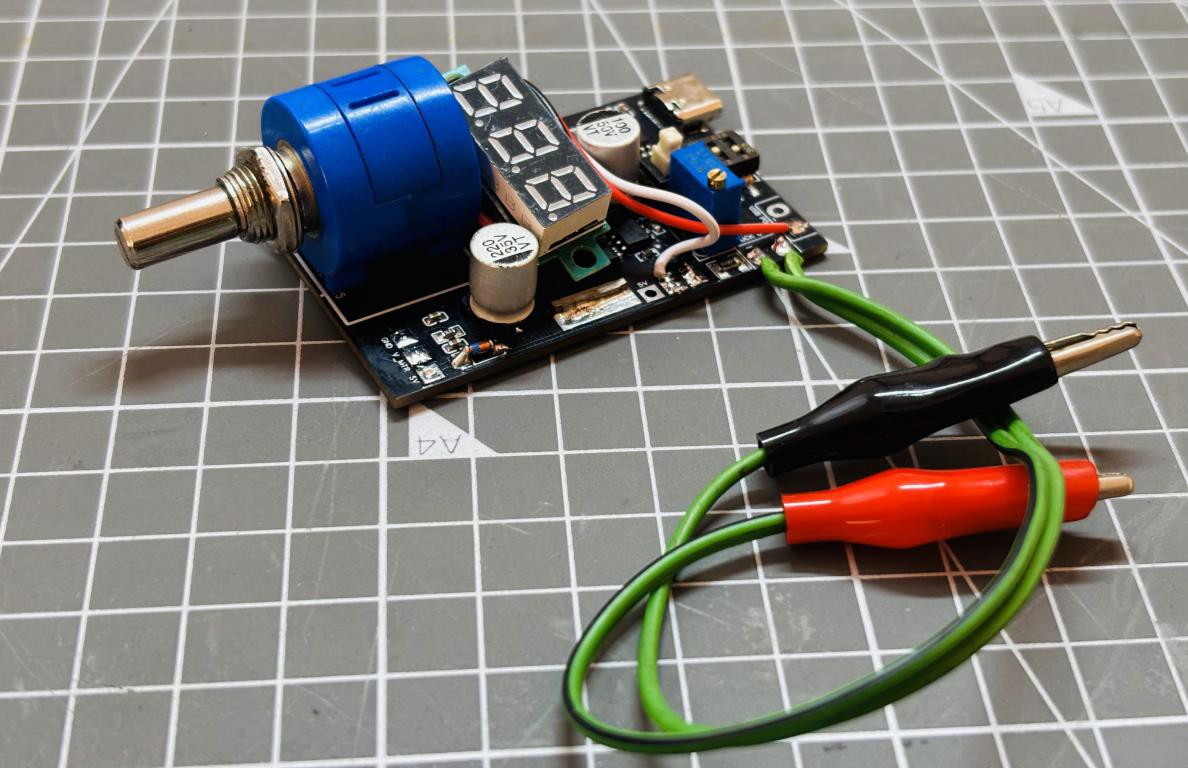
With this CH224k multiple voltages like 5,9,12,15,20V are possible with different settings of input jumpers. It can provide a max of 20V at 5A of constant current, hence a max power of 100W can be delivered. But we need a variable power supply, to implement this LM2576 buck converter is the best option to go with. First the power delivery voltage is selected then this voltage given to the buck converter circuit, a potentiometer is used to tune the voltage according to the one's need. Moreover here we have onboard voltage and current monitoring options.
With a built-in PD communication module, high integration level, and simplified peripherals, it ensures efficient functionality. The chip includes integrated output voltage detection and offers protections such as over-temperature and over-voltage safeguards. I have integrated all that things on a PCB from PCBWAY, PCBWAY can be a one stop solution to all your circuit DIY needs from PCB to stencil, from Assembly to 3D printing. With over 10 years of experience and remarkable work in this field PCBWAY becomes the number one choice among hobbyists. Sign-up now from here and get free coupons for your first PCB order.
Features:
Supports input voltage range from 4V to 22V.
Compatible with PD3.0/2.0, BC1.2, and various fast-charging protocols.
Offers USB Type-C PD support with positive and negative plug detection and automatic switching.
Includes E-Mark simulation, automatic VCONN detection, and supports up to 100W PD power requests.
Allows dynamic adjustment of requested voltage through multiple methods.
Features high integration in a single chip, simplified peripherals, and cost-effective design.
Equipped with built-in overvoltage protection (OVA) and over-temperature protection (OTA) modules.
Components Required:
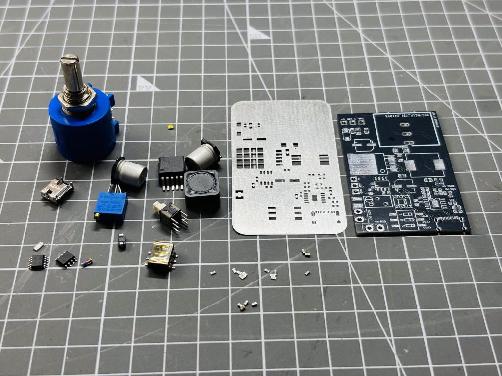
WCH224K IC
10K multi turn potentiometer
LM2596 Buck boost conversion Kit
10K, 1K resistor 0603
SMD LED 0603
LM358 op amp
Shunt 0.1OHM
DIP switches
Push ON/OFF switch
USB type C jack
5V Zener diode
3 wire voltmeter
1uf, 100nf, 10nf, 10uf capacitors 0603
PCB from PCBWAY
Circuit Diagram:
I divided the schematics into 3 main sections and subsections to each unit according to the input output. The first section carries power delivery output, second has buck conversion, 3rd has power monitoring.
First section:

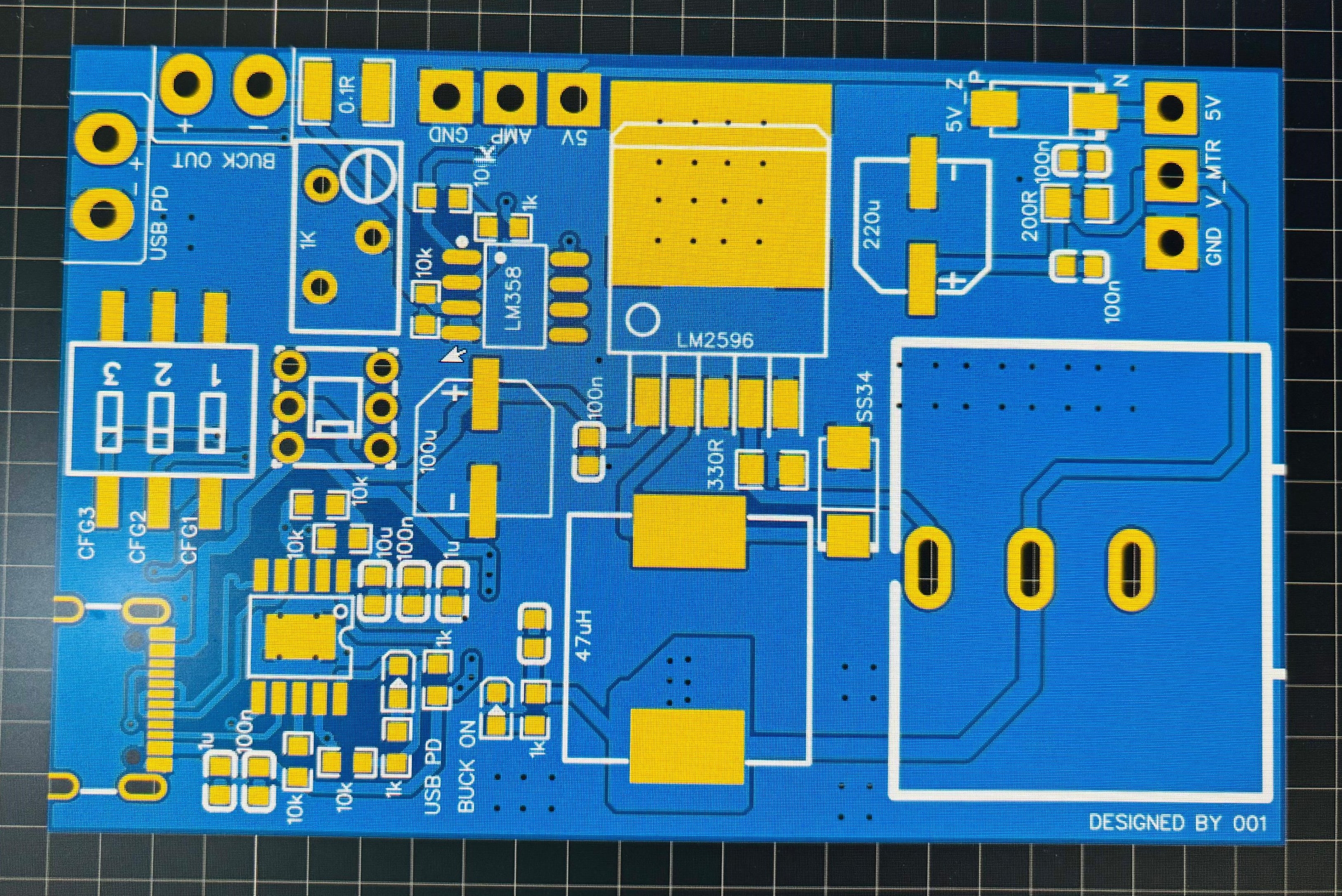
The main input type C, which takes input from the fast charging unit. CH224K is supplied from here, having some decoupling capacitors with it. Chip has 3 input pins stated as CFG1,2,3 which are connected to the DIP switch. As the switch is pulled up, respective pins go high and corresponding to which a power delivery output can be seen. The table for different voltages according to the configuration bits are given below. If the respective combination generates a power delivery then the LED connected to the PG pin is turned on.
Second Section:

It is separated with a push button switch, here a typical buck circuit with LM2596 IC can be seen which works well up to 30V 3A. But in our case max voltage is limited to 20V. The Buck section has an onboard LED which glows when the operation starts.
Third Section:

It carries a 5V zener diode voltage regulator which gets the input from USB supply, it is used to supply onboard voltmeter and ammeter. Voltmeter can be directly connected to the output supply to keep tracking the voltage set by multi-turn potentiometer. Secondly there is a DC amplifier which keeps the record of current, 0.1OHM shunt resistor at the output of buck converter circuit produces a voltage drop of 0.1V when 1A current is flowing through it. Dc amplifier used as a multiplier to amplify this 0.1V to 1V. In this way a simple voltmeter is able to show current readings. DC amplifier also have a 1K variable resistor which is used to calibrate the current output by tuning a little bit.
PCB Design:
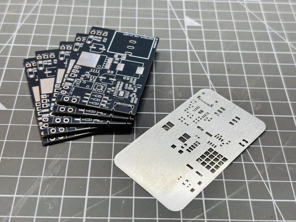
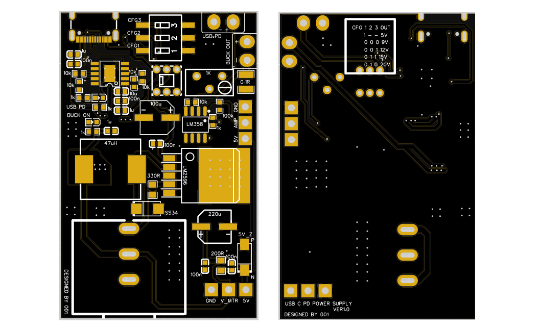
The PCB is designed in such a manner that output is isolated from the input supply not electrically but as of noise consideration. The LM2596 buck converter works at a high frequency, SS34 diode, capacitor and inductor forms that high frequency loop. Which can be kept as short as possible. All the configuration settings and push switch is kept easily accessible to user. Potentiometer is mounted in front to vary the voltage easily. The buck option can be activated only when the onboard push button is switched on. There are separate pins available to solder voltage and current monitoring meters.
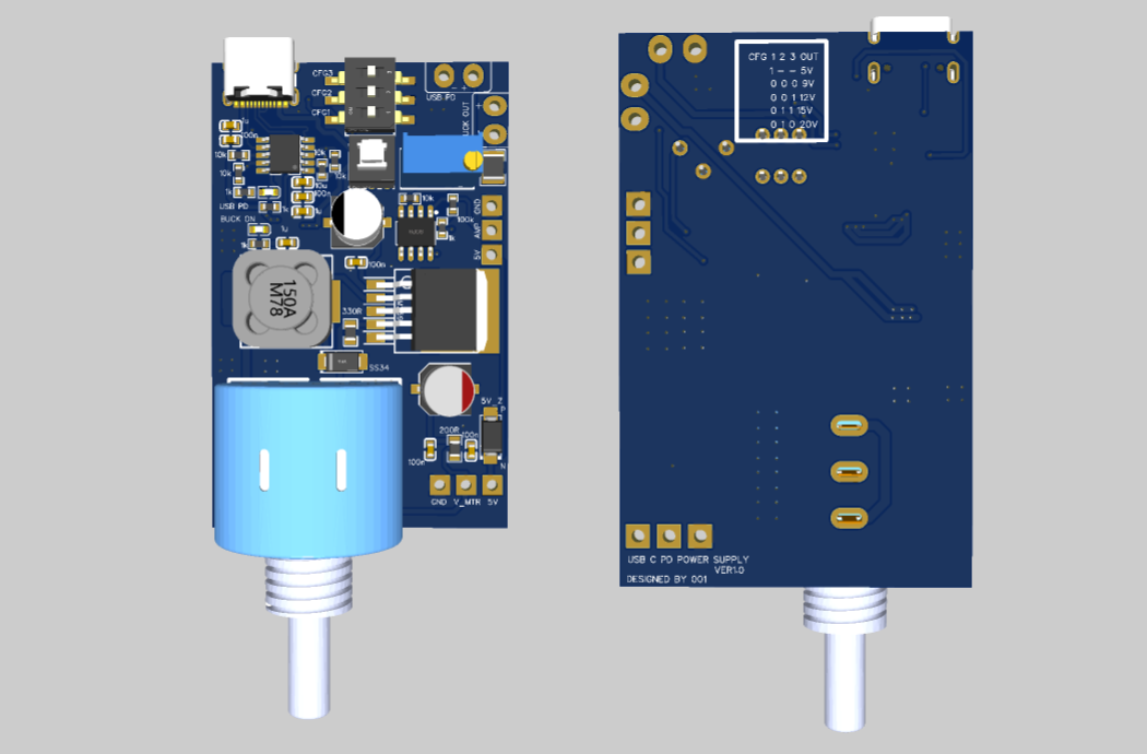
And finally two outputs can be seen one as buck output which is variable with multi turn pot, the second one is USB PD output which is variable with DIP configuration settings. The combination for the DIP switch can be found on the bottom silkscreen of the PCB. If any combination in the circuit doesn’t match the IC turn on hold option and output same as previous set voltage. The full circuit diagram, BOM, Gerber and CPL files can be directly downloaded from PCBWAY hub. You can order the same PCB to make your own smallest bench power supply from there.
PCB Assembly:
Assembling a PCB with a lot of components became a headache, but here I have a stencil ordered from PCBWAY for the same PCB. Which makes this work easy to do here are the main steps to assemble a PCB with the help of stencil service:
Make a platform and set the stencil on it.
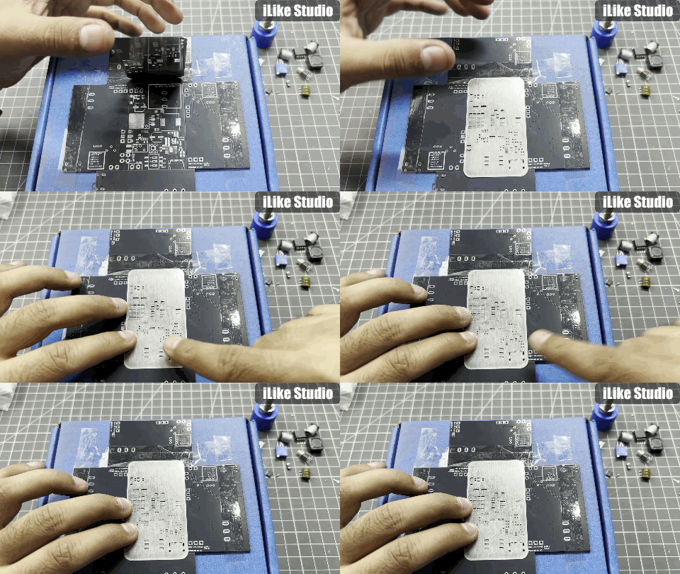
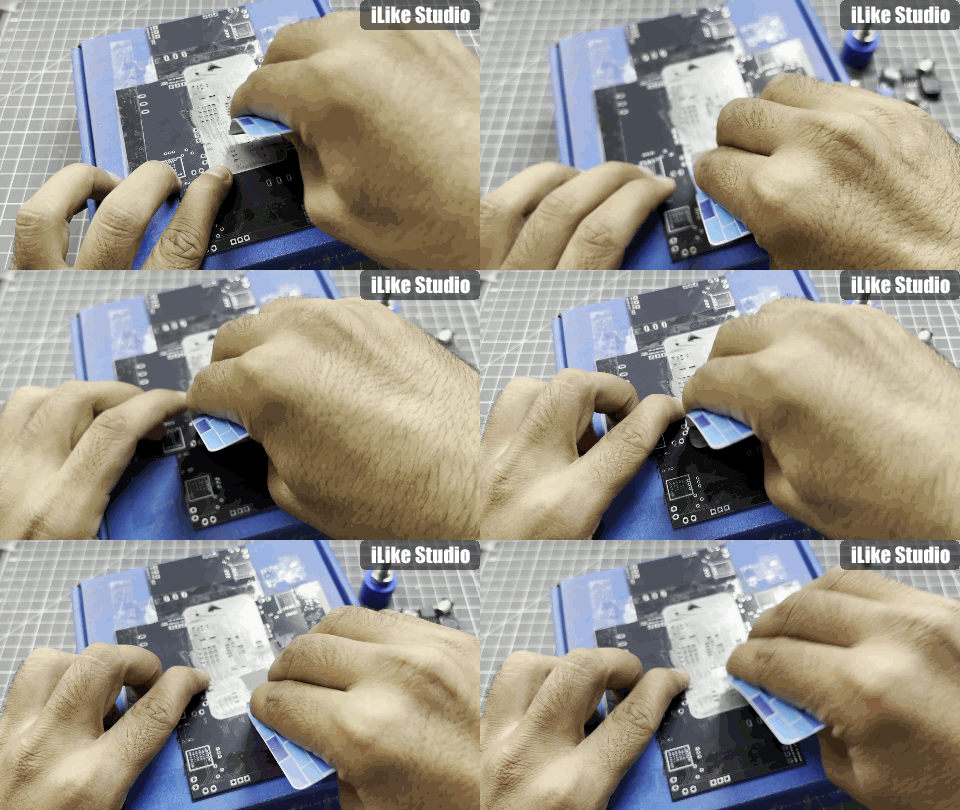
Apply solder paste properly.
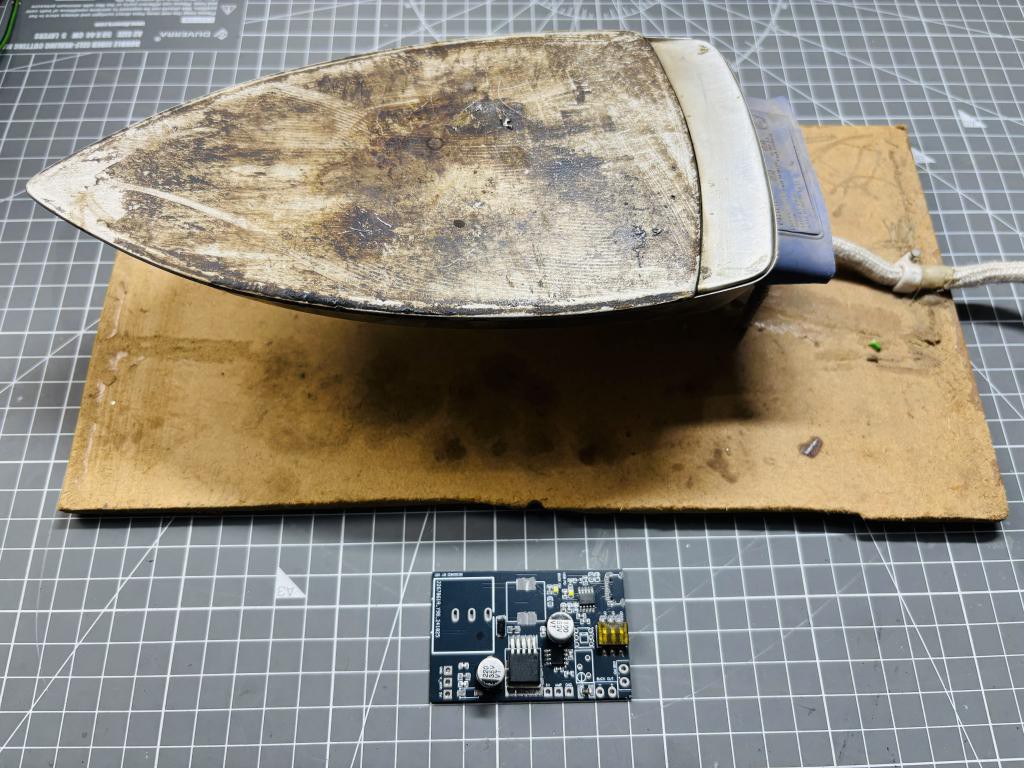
Solder with hot Iron. Here I have this home made one which works perfect for me.
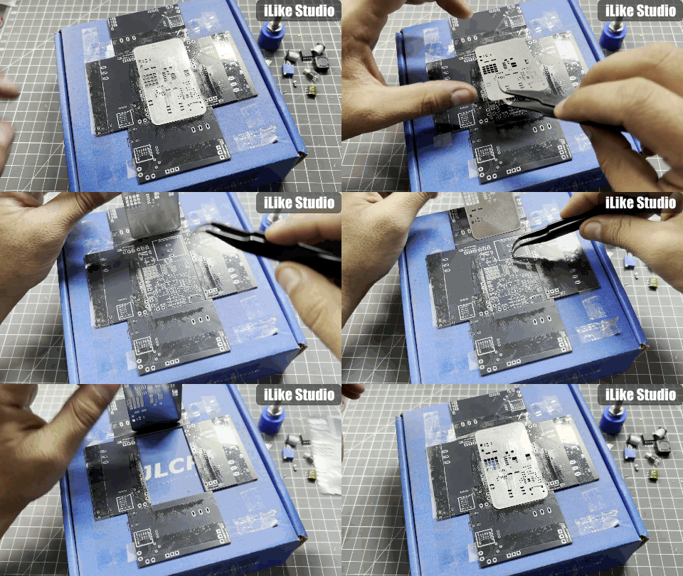
But if you do not want to mess it up just go with PCBWAY SMT assembly service, all the files are shared on the PCBWAY platform and can be directly downloaded from there.
What type of Fast charger is required:
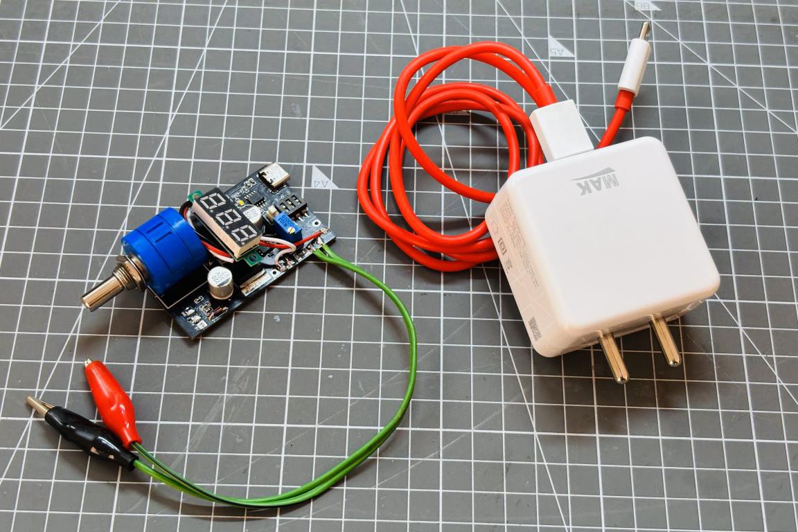
Because the main power source is itself a fast charger here, selecting the best charger which supports all the power delivery options is a prominent choice here. It is not necessary that a fast charger can output all of the voltages supported by the IC, but I will suggest to use GAN chargers, they come in a really small form factor and supply up to 120W of max power. In my case, the fast charger is only limited to 12v 6A which is around 72W of power.
First time Power On:
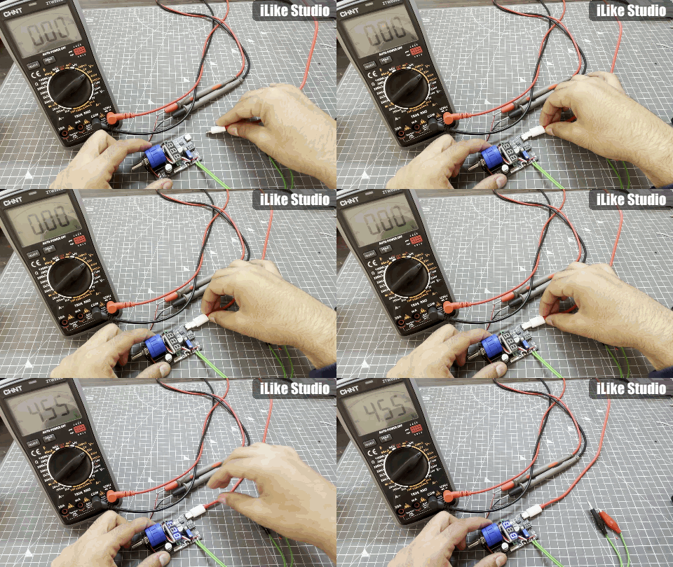
While turning the circuit first time power on, First make sure that USB PD configuration bits are set to minimum voltage i.e 5V. Then check the boost converter push button and it should be in OFF mode. Power on the supply with a simple charger first and turn on the buck section if nothing explodes and check if everything is working. In this mode first configure your onboard DC amplifier for current monitoring and solder required voltmeters at two places. After setting everything up, supply the power with a fast charger and check all the power delivery modes your fast charger can support. It is not necessary that a fast charger can output all of the possible combinations.
Testing and Working:
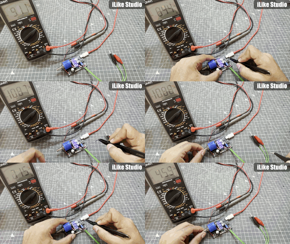
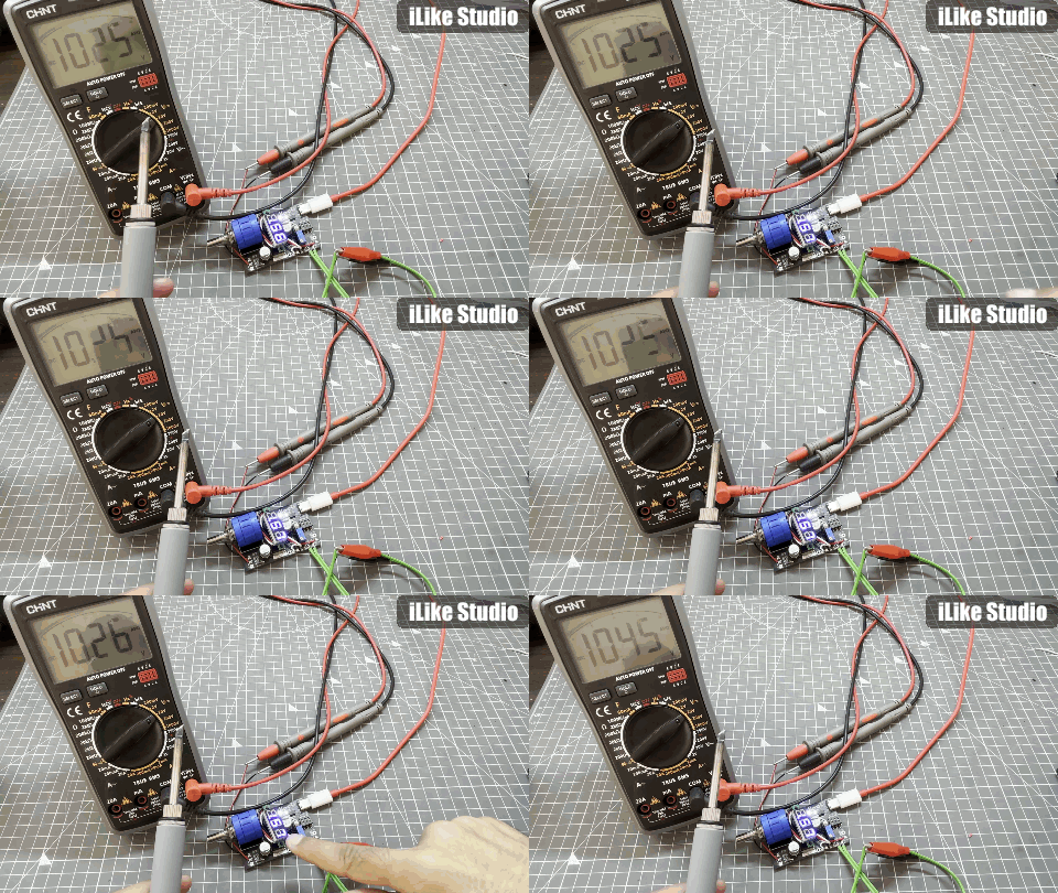
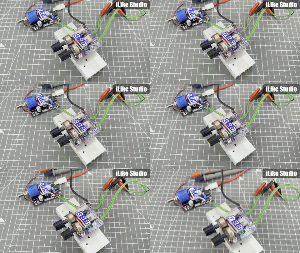
I have tested this power supply with a 70W DC soldering iron and with electronic load. All the features are in working, the current monitoring is precise up to 98%. It became a plug and play device for the hobbiest, now this small supply can deliver a power of whooping 100W to the test circuits. Download all the files from PCBWAY hub.
Soldering Iron test:
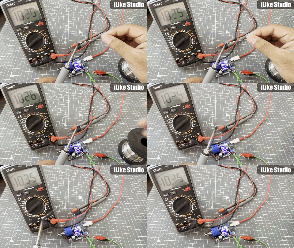
Electronic load test:
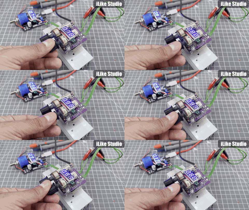
Looking for the best in PCB manufacturing? PCBWAY has you covered with exceptional quality, speedy service, and generous sponsorship opportunities! Visit PCBWAY website now and check all the amazing services offered by them at reliable prices.
100W Lab Bench Power Supply From a Fast Charger
*PCBWay community is a sharing platform. We are not responsible for any design issues and parameter issues (board thickness, surface finish, etc.) you choose.
- Comments(0)
- Likes(2)
- 0 USER VOTES
- YOUR VOTE 0.00 0.00
- 1
- 2
- 3
- 4
- 5
- 6
- 7
- 8
- 9
- 10
- 1
- 2
- 3
- 4
- 5
- 6
- 7
- 8
- 9
- 10
- 1
- 2
- 3
- 4
- 5
- 6
- 7
- 8
- 9
- 10
- 1
- 2
- 3
- 4
- 5
- 6
- 7
- 8
- 9
- 10
 More by Manoj kumar
-
 STK4141 Amplifier is hidden GOLD
Analog audio amplifiers are very powerful enough to make a high noise with stable quality factor. I ...
-
 More Bass Treble and Volume! With PT2313 DSP
When it comes to signal processing through a digital medium then DSPs are the one who comes into pla...
-
 Solar Power MPPT Control Li-ion Battery Charger
When talking about standalone single cell battery chargers only one popular name came into my mind t...
-
 AC Power Monitoring Using BL0937 IC
AC power monitoring is an amazing feature nowadays in IoT related applications, such as smart fans, ...
-
 100W Lab Bench Power Supply From a Fast Charger
Power supplies play a very important role in testing electronic circuits. Power supplies are used to...
-
 MPPT Solar LIPO Battery Charger
I was just charging my Li-ion battery manually with my IP2312 charger, the high current version I ha...
-
 DIY Portable Power Supply
Whenever I am travelling from one place to another, I used to keep my electronics with me. And somet...
-
 I made a Nano USB HUB
I want to use the USB hub internally in my laptop but the available ones are very bulky and do not s...
-
 I made an ARDUINO NANO Clone Board
I made a series of Arduino Atmega328 boards and every new version has something new. We always learn...
-
 Arduino Got Pro Max upgrade!!
I am aware of sensors, modules and integrated circuit used with microcontrollers like Arduino. And I...
-
 Minimal Component tester using Arduino
You might know component tester and its different versions made by many hobbyists. Today I have made...
-
 Making a Digital Light Measuring Meter
While working on a home automation project on light, the light intensity unit- lux (lumens per squar...
-
 IR Jammer circuit using NE555 timer
I am working on IR protocol in university research Centre and then an idea of IR jammer comes into m...
-
 Variable Current/Voltage DC power supply
To power up electronics circuits or while testing different voltage-ampere/power ranges are required...
-
 PCB soldering reflow hot Plate! A good Idea?
let’s talk about soldering in a new and easy method. Because I am working with SMT components and st...
-
 Non-contact Infrared temperature sensor using Arduino
Hello guys, I want to make my own most accurate temperature meter. When coming to the high temperatu...
-
 Arduino serial Programmer CH340N
There are lot of programmer boards that are compatible with Arduino. But the cheapest and smaller on...
-
 My own Arduino Nano Microcontroller board
Here is my new Arduino Nano board, This looks better with C-type and one step above compatible drive...
-
-
mammoth-3D SLM Voron Toolhead – Manual Drill & Tap Edition
140 0 0 -
-
AEL-2011 Power Supply Module
655 0 2 -
AEL-2011 50W Power Amplifier
567 0 2 -
-
-
Custom Mechanical Keyboard
769 0 0 -
Tester for Touch Screen Digitizer without using microcontroller
395 2 2 -
Audio reactive glow LED wristband/bracelet with NFC / RFID-Tags
364 0 1 -
-


