


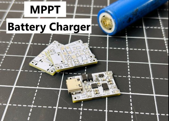


Solar Power MPPT Control Li-ion Battery Charger
When talking about standalone single cell battery chargers only one popular name came into my mind that is our versatile Li-Ion/Li-Po TP4056 battery charger. Which is vastly available and has a lot of features related to battery protection. The lithium batteries are easily available in the market with proper charging solutions, but when it comes to solar changing a few microcontroller projects can be seen over the web. I want to create a standalone solar battery charger module, and luckily I found one solution at consonance CN3165, Like TP4056 Li-ion, the charge current can be set externally with a single resistor.

Onboard features include undervoltage lockout, automatic recharge, the constant current charging, the maintenance charge mode(timer termination), charge/termination indicators and battery temperature monitoring. All the modes and battery charging process is given below with all details. Big thanks to PCBWay for sponsoring the PCBs for this project! Their high-quality manufacturing and quick turnaround made this build possible.
CN3165 and it’s Features:
The CN3165 is a complete constant-current /constant voltage linear charger for single cell Li-ion and Li Polymer batteries. The device contains an on-chip power MOSFET and eliminates the need for the external sense resistor and blocking diode. An on-chip adaptive cell can adjust charging current automatically based on the output capability of input power supply, so CN3165 is ideally suited for solar powered systems.
Thermal feedback regulates the charge current to limit the die temperature during high power operation or high ambient temperature. The regulation voltage is internally fixed at 4.2V with 1% accuracy, it can also be adjusted upwards with an external resistor. The charge current can be set externally with a single resistor. When the input supply is removed, the CN3165 automatically enters a low power sleep mode , dropping the battery drain current to less than 3uA.
Features:
- Suitable for Solar-Powered System
- On-chip Power MOSFET
- No external Blocking Diode or Current Sense Resistors Required
- Preset 4.2V regulation voltage with 1% accuracy, upwards adjustable with a resistor
- Continuous Charge Current Up to 1A
- Constant-Current/Constant-Voltage Operation
- Automatic Low-Power Sleep Mode When Input Supply Voltage is Removed
- Status Indication for LEDs or uP Interface
- C/10 Charge Termination
- Automatic Recharge
- Battery Temperature Sensing
PCBWay is the best solution out there I found for PCB fabrication. They offer a low-cost, highly reliable, and foolproof process from prototype to full-scale product manufacturing. With quick turnaround times, extensive material options, and exceptional customer support.
Circuit Diagram:
I have read the datasheet, and it depicts the application circuit with some protection features added on. The datasheet circuit is here:
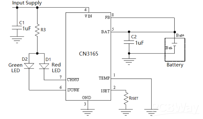
Here we need a resistor to set the maximum output battery charging current, A capacitor on battery terminal for power supply noise cancellation. And a few led indicators for battery changing and done mode. In single cell operation the feedback pin is directly connected to the battery terminal and continuously monitors the battery voltage for automatic charging restart and power down. The same charging IC can be used to charge more than 1 battery @1Amp maximum by feeding the feedback pin with voltage dividers.
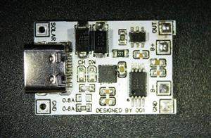
Modified Circuit:
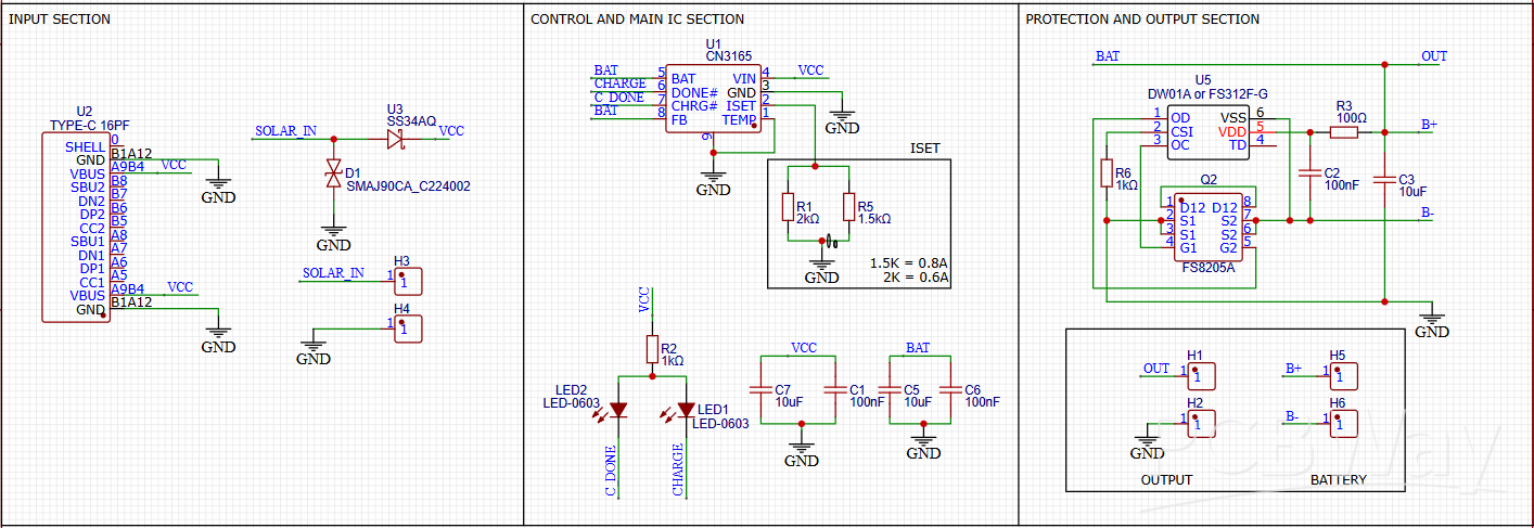
I modified the circuit to add some external protection features. I have added a USB type C input, a TVS diode to reject any spike in solar output and a forward bias diode to make it polarity friendly, which can be seen in the schematics.
In section 2, IC is placed itself with 2 resistors to set the current, led indicators and some coupling capacitors for the IC.
In section 3, output is taken from a pin header, And it also contains the same protection circuit which is there on TP4056. All this packed into a small form factor.
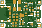
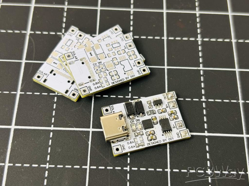
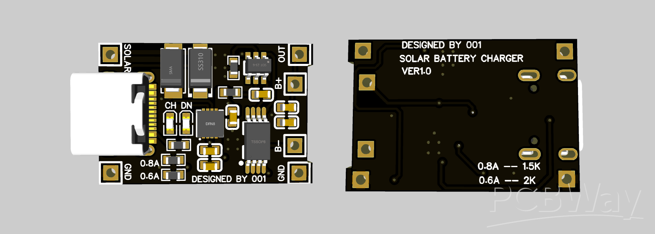
PCB Layout:
This is the Hardware level design I have implemented keeping all the noise and stabilization problems in mind. Tracks are made with enough calculations to carry max current hence delivering maximum power and reduce heat effects. Two onboard status Leds is to monitor battery charging. And to keep all the effects of switching section minimal on the input and output the PCB is divided according to the input to output flow. I kept the form factor same as TP4056 board, which makes this design more practical and easier to use as a standalone battery charging device. For input power USB type C and solder pads are given same as TP4056 design.
To order the same PCB, download all the required files from below. I always prefer to use PCBWAY and their assembly services. PCBWAY is the China based PCB manufacturer that provides services in PCBA, SMT, Stencil, 3D printing and Metal parts. Sign-up now and order your first PCB, get free coupons to order PCBs from the link given here. Just upload the files and select the required board parameters, BOM and CPL files can be used to order fully assembled boards.
BOM and Assembly Considerations:

When soldering, the best practice is to mount the IC and USB connector first. Then small capacitors, resistor and then Inductor. Because the IC pad and USB connector are very hard to solder with hand. If you don’t want to assemble the board then PCBWAY assembly services are the best option to go with.
Lithium Ion Battery Charging Modes:
Let’s dive deep into the charging process and see what is happening during the changing process of a Li-ion circuit.
Trickle Charging:
Trickle charging (also known as pre-charging) occurs in two stages: It is a type of battery protection feature which is only enabled if somehow the battery gets over discharge.
Say if nominal voltage is 3.7v, and battery is over discharged (such as below 2.8V), recovery charging is performed first to prevent the battery from being damaged by excessive current. At this time, the software is not yet started, and it is a hardware-controlled behaviour. The "trickle charging" in this stage refers to the charging process after the battery is over-discharged and before it returns to the boot voltage. The current in trickle charging is 1/10 of the max charging current, which is 0.1C (If max charge current is 1A as an example, the trickle charging current is 100mA).
The commonly mentioned trickle charging refers to the charging process that continues for a period of time. It is a type of constant voltage charging and limits the value of charging current; once the battery reaches its normal voltage (3.7v), the trickle changing mode is shut down and Constant current charging mode is enabled.
Constant Current and Constant voltage charging:
During the standard charging process, the battery is charged with a constant current equal to the maximum charging current. As the battery voltage rises steadily, the charging process switches to constant voltage charging (at near about 4.15v) when the voltage approaches the set maximum voltage. At this point, the charging current gradually decreases until it reaches 1/10 of the maximum charging current, at which point the charging process ends. The constant voltage changing mode is used to keep the battery healthy and not to degrade faster.
Charge current rating is mentioned on the battery, Defined by the C rating. C is a method of representing current with respect to the nominal capacity of the battery. For example, if the capacity of the battery is 1000mAh, then 1C is equal to a charging current of 1000mA (1A).
Charge Termination:
There are two typical charging termination methods: the minimum charging current method and the timer method (or a combination of both). The minimum current method monitors the charging current during the constant voltage charging stage and terminates the charging process when the charging current decreases to between 0.02C and 0.07C. The second method starts timing when the constant voltage charging stage begins and terminates the charging process after two hours of continuous charging. In modern era, the charge termination in mobiles has not stopped even if it’s showing 100% health, at this time charging continues with a very small current to increase the overall battery life.
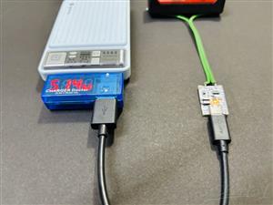
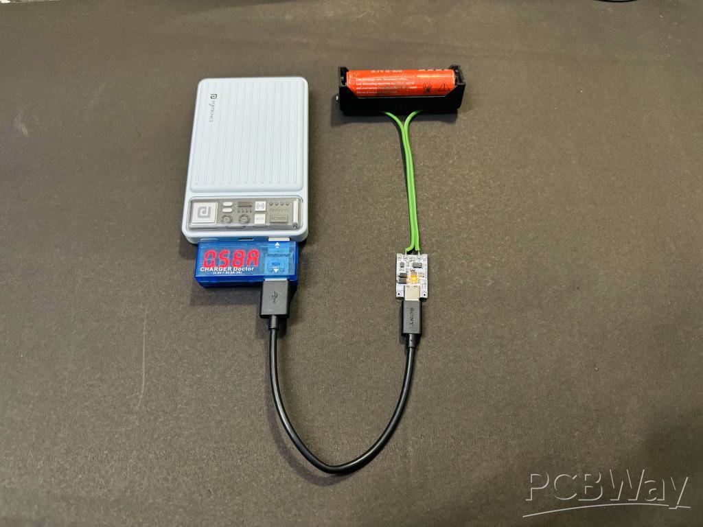
Testing and Working:
I powered on the board after assembling it with a power supply set to max current limit of 100mA so that if anything goes wrong, it will not damage anything. But worked in the first go, all the connections are correct, but always check the VCC and GND lines continuity before powering ON. So, I connected a 3.9V LI-ION battery with a max charge voltage of 4.2V. The default charging current is set. The charging current rating should match the battery rating, so I always recommend using a high C rated battery, while charging with 3A.
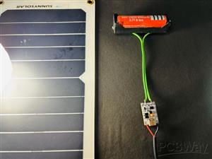
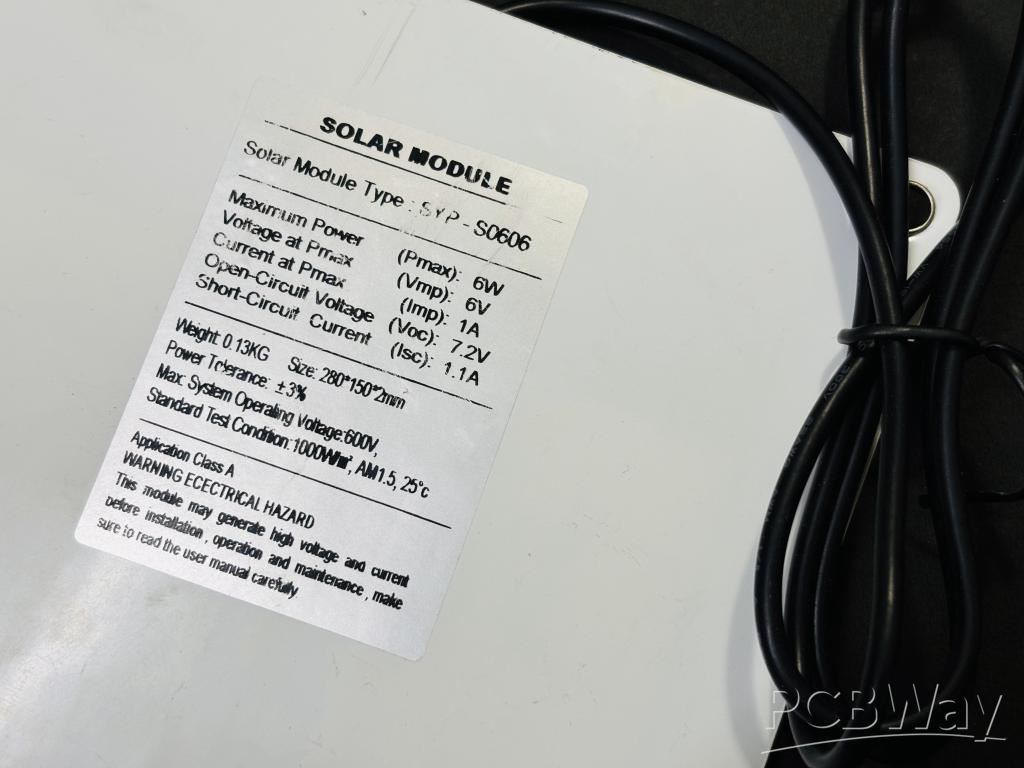
Solar Charging:

Simple Charging:
When charging the battery at full potential a very little heat is produced, which satisfies the 94% efficiency of this IC. I also have tested all protection features and all of them are working very normally. It is always recommended to check the output voltage of the board which should be in the range of 4.15-4.22 volts for the Li-ion battery. Try PCBWAY services from here, get free PCB coupons on first sign-up.
Solar Power MPPT Control Li-ion Battery Charger
*PCBWay community is a sharing platform. We are not responsible for any design issues and parameter issues (board thickness, surface finish, etc.) you choose.


Raspberry Pi 5 7 Inch Touch Screen IPS 1024x600 HD LCD HDMI-compatible Display for RPI 4B 3B+ OPI 5 AIDA64 PC Secondary Screen(Without Speaker)
BUY NOW
ESP32-S3 4.3inch Capacitive Touch Display Development Board, 800×480, 5-point Touch, 32-bit LX7 Dual-core Processor
BUY NOW
Raspberry Pi 5 7 Inch Touch Screen IPS 1024x600 HD LCD HDMI-compatible Display for RPI 4B 3B+ OPI 5 AIDA64 PC Secondary Screen(Without Speaker)
BUY NOW


- Comments(1)
- Likes(1)
 Log in to post comments.
 Reply
Reply

More by Manoj kumar
-
 Variable Current/Voltage DC power supply
To power up electronics circuits or while testing different voltage-ampere/power ranges are required...
Variable Current/Voltage DC power supply
To power up electronics circuits or while testing different voltage-ampere/power ranges are required...
-
 PCB soldering reflow hot Plate! A good Idea?
let’s talk about soldering in a new and easy method. Because I am working with SMT components and st...
PCB soldering reflow hot Plate! A good Idea?
let’s talk about soldering in a new and easy method. Because I am working with SMT components and st...
-
 Non-contact Infrared temperature sensor using Arduino
Hello guys, I want to make my own most accurate temperature meter. When coming to the high temperatu...
Non-contact Infrared temperature sensor using Arduino
Hello guys, I want to make my own most accurate temperature meter. When coming to the high temperatu...
-
 Arduino serial Programmer CH340N
There are lot of programmer boards that are compatible with Arduino. But the cheapest and smaller on...
Arduino serial Programmer CH340N
There are lot of programmer boards that are compatible with Arduino. But the cheapest and smaller on...
-
 My own Arduino Nano Microcontroller board
Here is my new Arduino Nano board, This looks better with C-type and one step above compatible drive...
My own Arduino Nano Microcontroller board
Here is my new Arduino Nano board, This looks better with C-type and one step above compatible drive...
-
 50Watts Audio Amplifier using TDA7265
Home theaters and speaker systems are very popular due to Bass songs, releasing everyday and I am ve...
50Watts Audio Amplifier using TDA7265
Home theaters and speaker systems are very popular due to Bass songs, releasing everyday and I am ve...
-
 STK4141 Amplifier is hidden GOLD
Analog audio amplifiers are very powerful enough to make a high noise with stable quality factor. I ...
STK4141 Amplifier is hidden GOLD
Analog audio amplifiers are very powerful enough to make a high noise with stable quality factor. I ...
-
 Solar Power MPPT Control Li-ion Battery Charger
When talking about standalone single cell battery chargers only one popular name came into my mind t...
Solar Power MPPT Control Li-ion Battery Charger
When talking about standalone single cell battery chargers only one popular name came into my mind t...
-
 AC Power Monitoring Using BL0937 IC
AC power monitoring is an amazing feature nowadays in IoT related applications, such as smart fans, ...
AC Power Monitoring Using BL0937 IC
AC power monitoring is an amazing feature nowadays in IoT related applications, such as smart fans, ...
-
 100W Lab Bench Power Supply From a Fast Charger
Power supplies play a very important role in testing electronic circuits. Power supplies are used to...
100W Lab Bench Power Supply From a Fast Charger
Power supplies play a very important role in testing electronic circuits. Power supplies are used to...
-
 MPPT Solar LIPO Battery Charger
I was just charging my Li-ion battery manually with my IP2312 charger, the high current version I ha...
MPPT Solar LIPO Battery Charger
I was just charging my Li-ion battery manually with my IP2312 charger, the high current version I ha...
-
 DIY Portable Power Supply
Whenever I am travelling from one place to another, I used to keep my electronics with me. And somet...
DIY Portable Power Supply
Whenever I am travelling from one place to another, I used to keep my electronics with me. And somet...
-
 I made a Nano USB HUB
I want to use the USB hub internally in my laptop but the available ones are very bulky and do not s...
I made a Nano USB HUB
I want to use the USB hub internally in my laptop but the available ones are very bulky and do not s...
-
 I made an ARDUINO NANO Clone Board
I made a series of Arduino Atmega328 boards and every new version has something new. We always learn...
I made an ARDUINO NANO Clone Board
I made a series of Arduino Atmega328 boards and every new version has something new. We always learn...
-
 Arduino Got Pro Max upgrade!!
I am aware of sensors, modules and integrated circuit used with microcontrollers like Arduino. And I...
Arduino Got Pro Max upgrade!!
I am aware of sensors, modules and integrated circuit used with microcontrollers like Arduino. And I...
-
 Minimal Component tester using Arduino
You might know component tester and its different versions made by many hobbyists. Today I have made...
Minimal Component tester using Arduino
You might know component tester and its different versions made by many hobbyists. Today I have made...
-
 Making a Digital Light Measuring Meter
While working on a home automation project on light, the light intensity unit- lux (lumens per squar...
Making a Digital Light Measuring Meter
While working on a home automation project on light, the light intensity unit- lux (lumens per squar...
-
 IR Jammer circuit using NE555 timer
I am working on IR protocol in university research Centre and then an idea of IR jammer comes into m...
IR Jammer circuit using NE555 timer
I am working on IR protocol in university research Centre and then an idea of IR jammer comes into m...
-
Variable Current/Voltage DC power supply
To power up electronics circuits or while testing different voltage-ampere/power ranges are required...
-
PCB soldering reflow hot Plate! A good Idea?
let’s talk about soldering in a new and easy method. Because I am working with SMT components and st...
-
Non-contact Infrared temperature sensor using Arduino
Hello guys, I want to make my own most accurate temperature meter. When coming to the high temperatu...
-
Arduino serial Programmer CH340N
There are lot of programmer boards that are compatible with Arduino. But the cheapest and smaller on...
-
My own Arduino Nano Microcontroller board
Here is my new Arduino Nano board, This looks better with C-type and one step above compatible drive...
-
50Watts Audio Amplifier using TDA7265
Home theaters and speaker systems are very popular due to Bass songs, releasing everyday and I am ve...
-
STK4141 Amplifier is hidden GOLD
Analog audio amplifiers are very powerful enough to make a high noise with stable quality factor. I ...
-
Solar Power MPPT Control Li-ion Battery Charger
When talking about standalone single cell battery chargers only one popular name came into my mind t...
-
AC Power Monitoring Using BL0937 IC
AC power monitoring is an amazing feature nowadays in IoT related applications, such as smart fans, ...
-
100W Lab Bench Power Supply From a Fast Charger
Power supplies play a very important role in testing electronic circuits. Power supplies are used to...
-
MPPT Solar LIPO Battery Charger
I was just charging my Li-ion battery manually with my IP2312 charger, the high current version I ha...
-
DIY Portable Power Supply
Whenever I am travelling from one place to another, I used to keep my electronics with me. And somet...
-
-
Commodore 64 1541-II 1581 Floppy Disk Drive C64 Power Supply Unit USB-C 5V 12V DIN connector 5.25
249 1 3 -
Easy to print simple stacking organizer with drawers
103 0 0 -
-
-
-
-
-
Modifying a Hotplate to a Reflow Solder Station
1189 1 6 -
MPL3115A2 Barometric Pressure, Altitude, and Temperature Sensor
667 0 1 -


