8-ch N-Mos Breakout
8Ch NMOS Breakout Module
As a companion module to my recently published 8Ch PMOD breakout board,
I decided to do a similar PCB, but with NMOS devices instead. This opens up more possibilities for proper testing and prototyping, as PMOS and NMOS devices has different use applications, and most importantly, can sometimes even be combined for a particular purpose, like an H-Bridge motor driver, for example.
 8Ch NMOS Breakout
What is on the PCB?
As NMOS devices function quite differently from their PMOS counterparts, it did not make sense to reuse the PMOS board, and just change the devices… although some people may be tempted to think you could…
The N Channel Mosfet basically “works in mirrored mode” from a P Channel one, and is used to do so-called ” LOW Side switching” which means that your load connects to the positive power rail, and then to the DRAIN pin of the MOSFET, with the source being connected to ground… ( It can sometimes also be used the other way around… but lets not go there now….
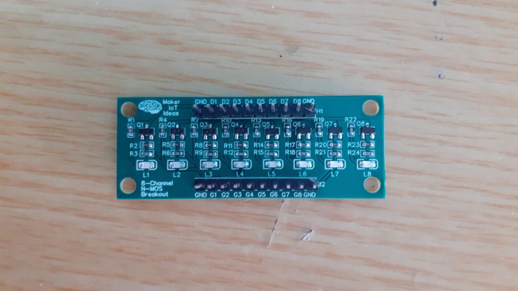
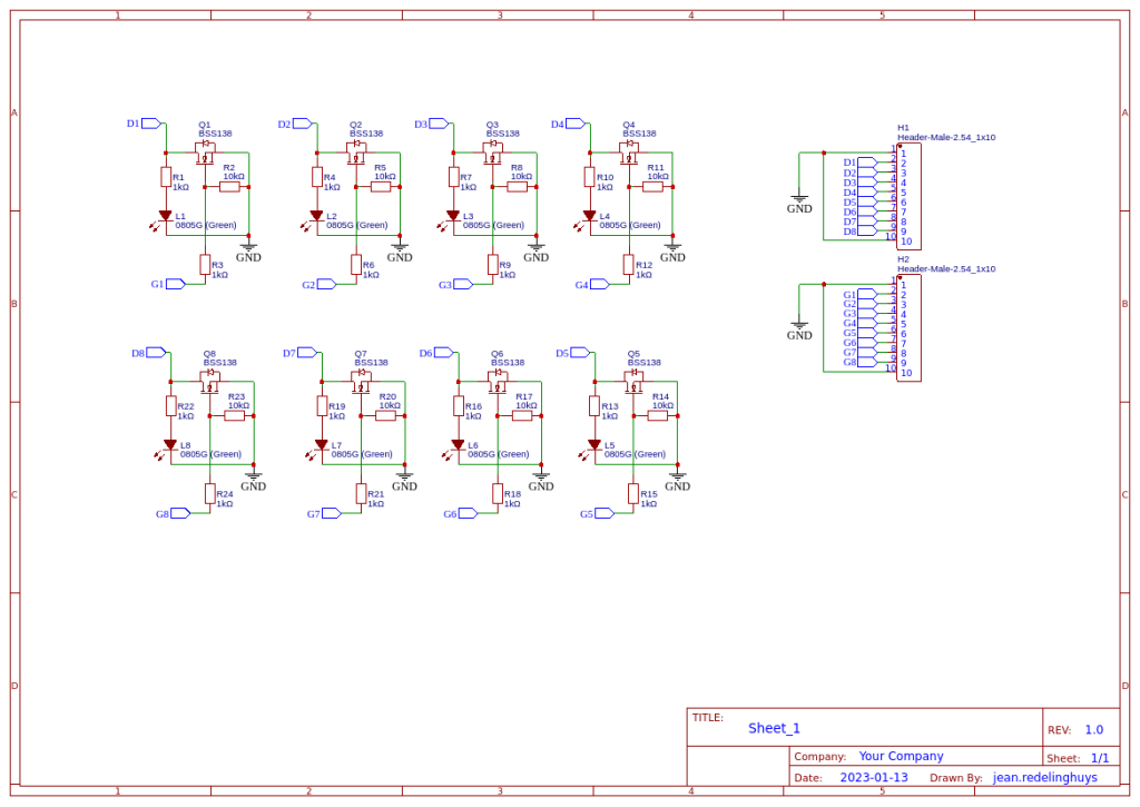
The current prototype PCB contains 8 BSS138 NMOS Mosfets, in my case, with is capable of about 800mA of current… All source pins are internally connected to ground. This forces you to use this module as a low side switch…
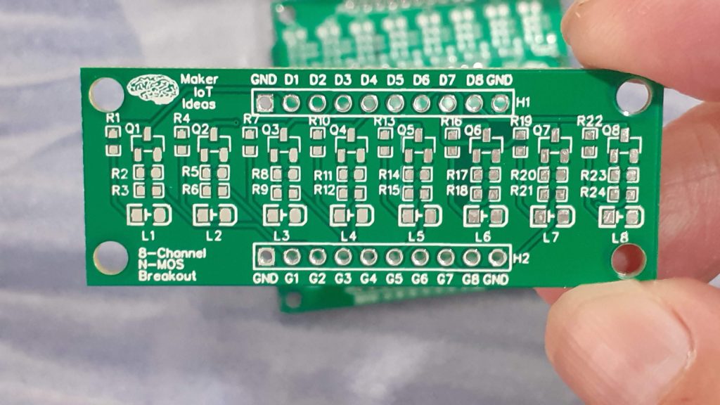
Two 10-way 2.54mm headers are provided, with a ground pin on Pin 1 and 10 of each of these.
The Drain pins of each NMOS device is available on the top header, labeled D1 through D8, and the Gate pins of each respective NMOS device is available on the bottom header, labelled G1 through G8.
Each gate has a pull-down resistor to ground, to keep it from flapping around, as well as a gate resistor. In my case, I selected to use a 10k pulldown, and a 1k gate resistor, as that is sufficient for my general needs…
Each NMOS device also has a LED signal indicator, to assist in visual confirmation of a specific channel’s state.
 PCB Top Side
The Schematic
 Schematic
Using the breakout
The module is very easy to use, and as briefly mentioned above, you are only required to connect one side of your load to the positive supply rail, and the other side to the drain pin of your choice.
Connect the ground pins of the module to your ground rail.
The Gate pin, with a corresponding number to the drain you have selected, can now be connected to your GPIO of choice on a microcontroller.
Drive the pin High to switch on the load, drive it log to switch off. Easy.
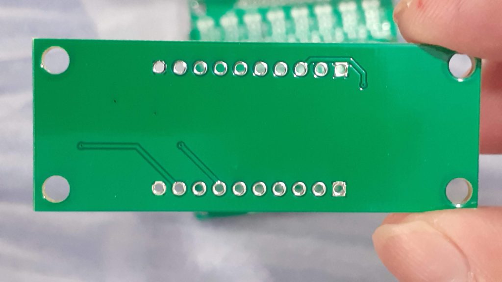
Please note: While the NMOS devices used on the board can handle quite a lot of current, (800mA in the case of the BSS138), it is not recommended to try and pull too much current through a single channel. The PCB traces can safely handle about a maximum of 300 to 400mA per channel.
 PCB Bottom
Example code for using the breakout (Arduino)
// Example code for 8Ch NMOS breakout
int Gate1 9;
int Gate2 10;

void setup() {
  // drive the two gate pins low to ensure NMOS devices
  // are in a positively known state at startup
  digitalWrite(Gate1,LOW);
  digitalWrite(Gate2,LOW);
  // Set gpio to output mode
  pinMode(Gate1,OUTPUT);
  pinMode(Gate2,OUTPUT);

}

void loop() {
  // Toggle the two channels in an alternating pattern
  digitalWrite(Gate1,!digitalRead(Gate1));
  digitalWrite(Gate2,!digitalRead(Gate1));
  delay(1000);

}
![]() Author makeriot2020Posted on January 27, 2023Categories Breakout Board Modules, Custom PCB Design, ElectronicsTags Arduino, Electronics, ESP32, ESP8266, Raspberry Pi Pico, STM32 Edit "8Ch NMOS Breakout Module"
Author makeriot2020Posted on January 27, 2023Categories Breakout Board Modules, Custom PCB Design, ElectronicsTags Arduino, Electronics, ESP32, ESP8266, Raspberry Pi Pico, STM32 Edit "8Ch NMOS Breakout Module"
// Example code for 8Ch NMOS breakout
int Gate1 9;
int Gate2 10;
void setup() {
// drive the two gate pins low to ensure NMOS devices
// are in a positively known state at startup
digitalWrite(Gate1,LOW);
digitalWrite(Gate2,LOW);
// Set gpio to output mode
pinMode(Gate1,OUTPUT);
pinMode(Gate2,OUTPUT);
}
void loop() {
// Toggle the two channels in an alternating pattern
digitalWrite(Gate1,!digitalRead(Gate1));
digitalWrite(Gate2,!digitalRead(Gate1));
delay(1000);
}

8-ch N-Mos Breakout
*PCBWay community is a sharing platform. We are not responsible for any design issues and parameter issues (board thickness, surface finish, etc.) you choose.
- Comments(0)
- Likes(1)
-
 (DIY) C64iSTANBUL
Jan 28,2023
- 0 USER VOTES
- YOUR VOTE 0.00 0.00
- 1
- 2
- 3
- 4
- 5
- 6
- 7
- 8
- 9
- 10
- 1
- 2
- 3
- 4
- 5
- 6
- 7
- 8
- 9
- 10
- 1
- 2
- 3
- 4
- 5
- 6
- 7
- 8
- 9
- 10
- 1
- 2
- 3
- 4
- 5
- 6
- 7
- 8
- 9
- 10
 More by Jean Redelinghuys MakerIoT2020
-
 PCB_MCP23008_2023-10-08
MCP23008 BreakoutI designed this breakout to assist me during prototyping my next version of the “RP...
-
 PCB_XiaoRP2040-Mouse-REV2
Xiao RP2040 Joystick Mouse – revision 2.00Revision 1.0 of the ProjectOver the last few months, I hav...
-
 Multi Purpose IO Card
Multi-Purpose IO CardWhen we are working on a prototype, we always need access to pushbuttons, encod...
-
 Variable Voltage Power Module
Powering electronics projects are always challenging. This Variable vol...
Variable Voltage Power Module
Variable Voltage Power ModulePowering electronics projects are always challenging. This Variable vol...
-
 I2C Matrix Keypad
An I2C Matrix KeypadThe completed I2C Matrix KeypadIn a previous post this month I introduced my 4×4...
-
 ESP32-S Development Board, in "Arduino Uno" form factor
UPDATE 24/06/2023:This board now has a Hardware Revision 2.0 available. It is the same board but wit...
-
 W307186ASC94_Gerber_PCB_USB-Ports
USB Power Supply ModuleUSB Ports are quite handy to power all our day-to-day electronic devices, but...
-
 Atmega 328P based PWM controller Card
ATMega 328P Based PWM controller CardAs part of my recent ESP-12E I2C Base Board project, I designed...
-
 W307186ASC71_Gerber_PCB_ESP-Now Remote
Today we will look at the remote control unit for the Robotic Toy Car – Part 6.The project is close ...
-
 W307186ASV69_Gerber_PCB_Robot-Car-MCU-Board Prototype
In our last project, we started working on repurposing an old toy car. In this part, Robot Toy Car –...
-
 W307186ASV62_Gerber_PCB_DUAL-H-Bridge
by makeriot2020 on May 27, 2022Many of us have old toys laying around the house, they belong to ou...
-
 CAN-BUS Breakout
Breadboard Compatible CAN-BUS Breakout ModuleWhat is this:Some of us have already used the commonly ...
-
 RA-02 Breakout with Level converters
Breadboard and beginner-friendly RA-02 Breakout ModuleMost Makers and electronics enthusiasts may al...
-
 ATMEGA328P Module with integrated LoRa and CAN Bus
ATMEGA328P Module with integrated LoRa and CAN-BUSINTRODUCTIONIn my quest to perfect my LoRa telemet...
-
 Sx127x-Ra-02-Test-Module with ATMEGA328P-AU
SX127x LoRa/FSK/OOK Prototype Radio BoardI recently had a requirement to do some automation/telemetr...
-
 USB-ASP Programmer ATMEGA8
Build your own USB-ASP Programmer CloneBymakeriot2020 FEB 21, 2022 Arduino, ASP programmerUsing mor...
-
 ATTiny1616-LIGHT-Controller-with-CAN_B_PCB_ATTiny1616-LIGHT-Controller-with-C_2024-09-11
Assembly of the ATTiny1616 Can bus controller PCBThe Assembly of the ATTiny1616 Can Bus Controller P...
-
 ATTiny1616QFN-CAN-Remote-Neopixel-Ligh_PCB_ATTiny1616QFN-CAN-Remote-Neopixel-2024-09-11_2024-09-11
NeoPixel CAN-Bus Module with local controlAs part of my current project to add NeoPixels to the cabi...
-
-
mammoth-3D SLM Voron Toolhead – Manual Drill & Tap Edition
229 0 0 -
-
AEL-2011 Power Supply Module
755 0 2 -
AEL-2011 50W Power Amplifier
627 0 2 -
-
-
Custom Mechanical Keyboard
822 0 0 -
Tester for Touch Screen Digitizer without using microcontroller
448 2 2 -
Audio reactive glow LED wristband/bracelet with NFC / RFID-Tags
399 0 1 -
-


