
|
arduino IDEArduino
|
|
|
|
LibreCAD |
|
|
|
OpenBuilds CAM |
|
|
|
OpenBuilds Control |
ATMEGA4808 Development Card in Arduino Form Factor
ATMEGA4808 – An Improvement on my previous design? Or Not…
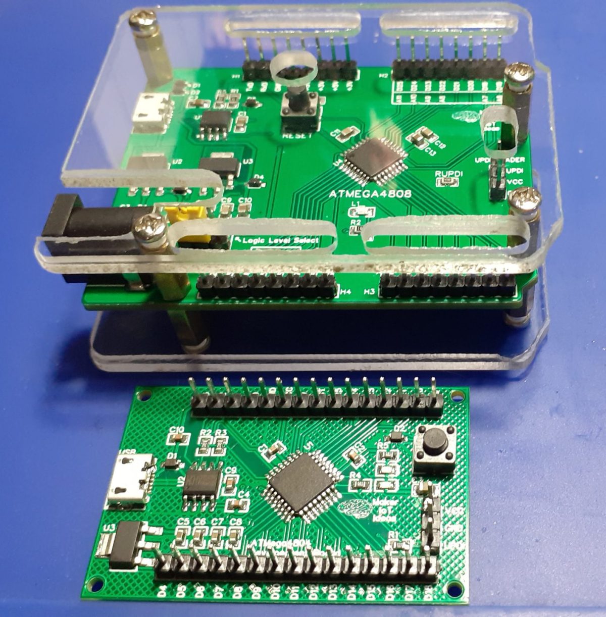
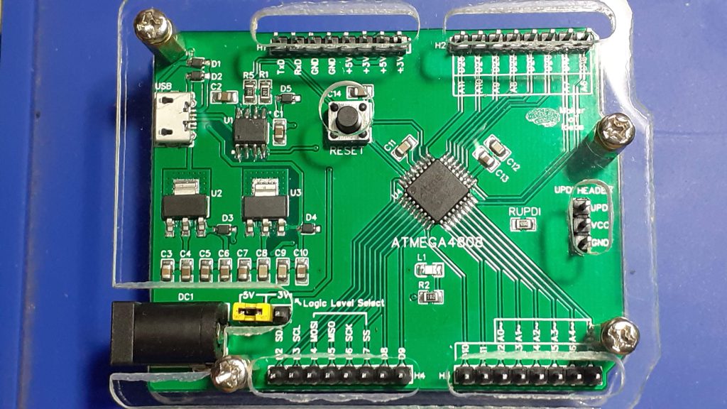 Atmega4808 Development Card in Acrylic Shell
When I first started playing around with the ATMEGA4808, I was impressed as well as disappointed by the Arduino Every “Clone” that I got online. Impressed with the Microprocessor, but disappointed in the way the development board worked, the lack of documentation etc.
I set out to change that by doing my own version, something that I do quite a lot. If I don’t like something, and it is in my ability to create/design my own version, minus any of the perceived(in my opinion mostly) flaws of the original design, I usually do just that.
With that mindset firmly in place, a few weeks ago, I did indeed redesign an ATMEGA4804-based development module, and it worked flawlessly…
As time went by, that little irritating voice in my head got louder and louder… add this, change that, what if it was like this etc… Many makers will know exactly which little voice I am talking about.
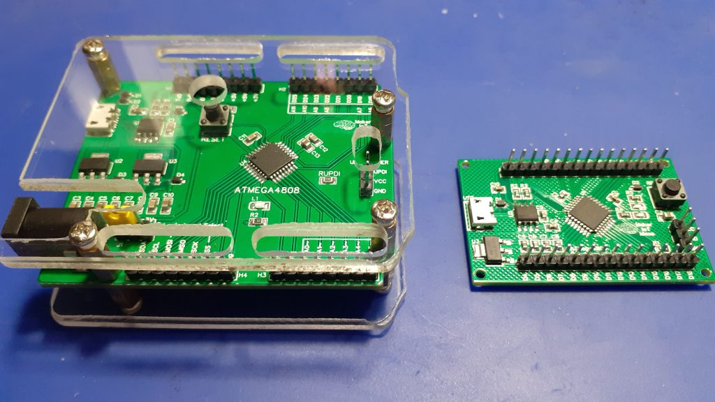 Two Atmega4808 Modules, side-by-side
So what did I change?
The short answer to that is a lot. the long and detailed, well let’s see…
Added an additional LDO voltage regulator, to provide more current.
A DC barrel jack was included, enabling us to power this from 7v to 12vDC
Changeable logic level ( switching entire board between 3.3v and 5v operation )
with a single jumper.
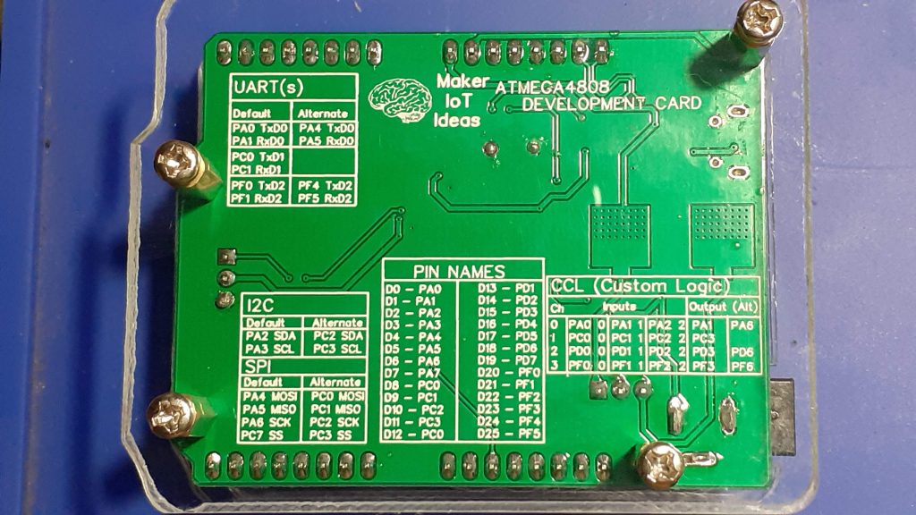
Improved labelling of GPIO functions (on the back of the PCB), listing alternative functions etc for each GPIO
Put all that into the standard Arduino Uno Footprint…
So, did any of that really matter?
Once again, two answers, one long, one short… so here goes…
The added DC barrel jack, with the two dedicated LDO voltage regulators, adds flexibility to power the device externally, opening up possibilities to use it in a stand-alone project, not only on the bench.
The Logic level switching, which at the time, seemed like a very very good idea, now no longer seems so important…
Using the Arduino Uno footprint, yeah, so what, it is a neat layout, but apart from using a somewhat ” traditional” footprint, is only cosmetic…
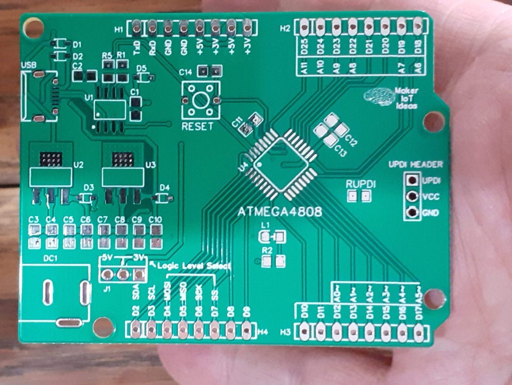
That leaves only the updated silkscreen on the back of the PCB, as well as better labelling on the front…
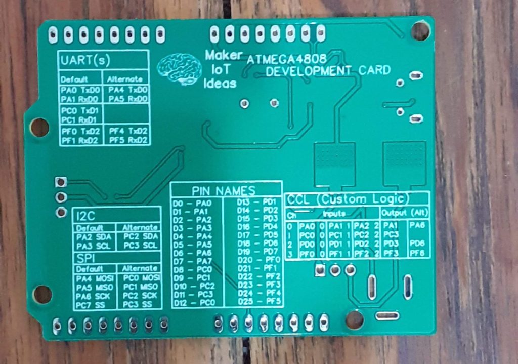 Back Silkscreen
 Front silkscreen
As far as information goes, yes, this is a great help. It will definitely save some time reading datasheets and looking up other stuff…
Does this mean the project was a failure?
Definitely not. I am not negative, but instead, have a tongue-in-the-cheek attitude about how sidetracked I became. I mean, this is basically the exact same board, with just a different form factor. So, in that case, think about it in the context of an Arduino UNO and Arduino NANO. Both of them use the exact same processor but only differ in footprint. ( as well as a few other cosmetic things and functions – the nano having additional analog inputs etc.).\
I am sure that the new form factor will appeal to some, and others will feel it was a completely unneeded design.
The Schematic
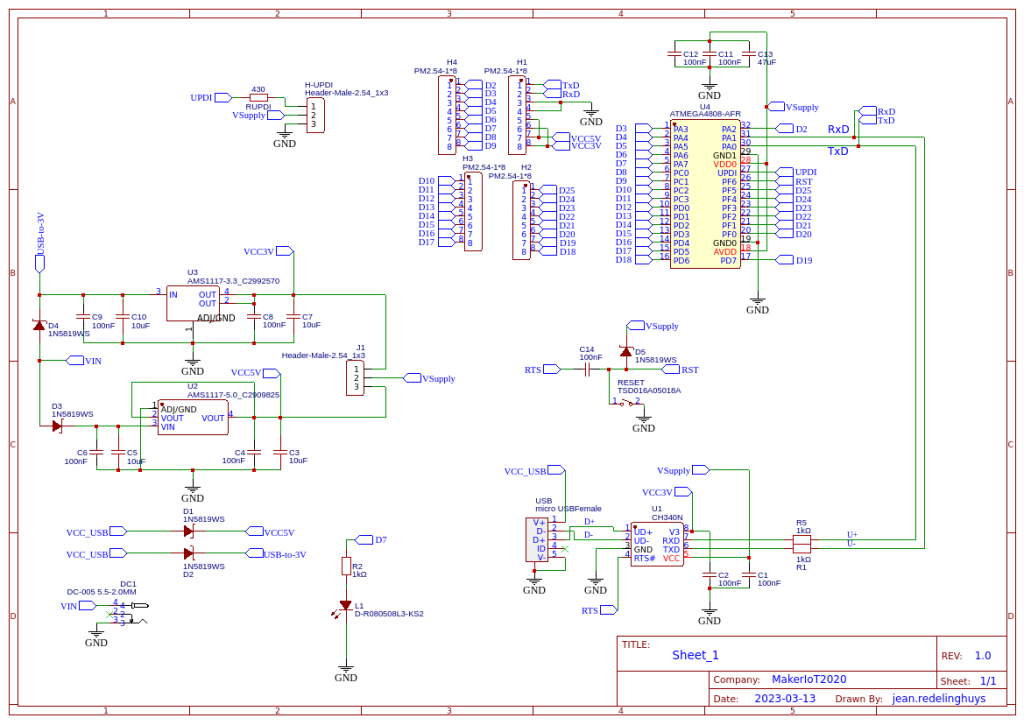 ATMEGA4808 Schematic
The schematic does not contain any surprises. everything is basically similar to my initial breakout module design, with the exception of the power section. I tried something different, and the jury is still out on how well it actually worked.
When powered from USB, the 3.3v LDO Voltage regulator gets fed directly from the USB Voltage, through a protection diode of course.. Similarly, when powering the device using the DC power jack, both LDO regulators are once again fed separately… for the time being, it seems to work well. Time will tell if it was the correct way to do things.
PCB Design

Top Layer

Bottom Layer
A lot of care was taken to attempt routing of all tracks at the shortest distance possible, as well as using differential pairs for the UART, SPI and I2C peripherals. PCB heatsinks for the LDO regulators, as well as ground planes on both side of the PCB, was also implemented.
Assembly
The assembly of the ATMEGA4808 development card, as I named the creation, can be done entirely with a standard soldering iron and steady hands, but I chose to order a stencil with the PCB and reflow the PCB on a hotplate.
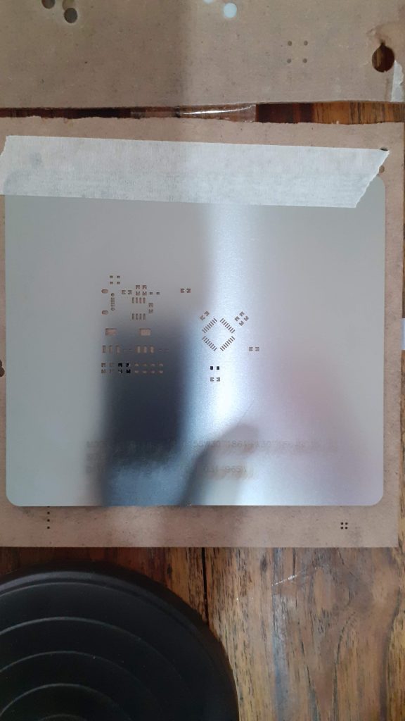
Stencil for SMD assembly
I prefer this way of assembly, as it is generally faster, looks neater, and ultimately uses less solder paste. This particular build did however give me a few headaches, which may be the underlying reason for my tongue-in-the-cheek attitude towards this PCB…
Let us take a look at some of the issues that I encountered
The Micro USB B connector that I used, seems to be quite sensitive to heat. I have a few different batches of these, and some are good, while others are just terrible. ( this happens because I did not buy them all from a reputable supplier, but opted for an online supplier instead – NOT LCSC as I normally do).
This resulted in having to change USB connectors a few times.
The second issue was the CH340N USB to Serial chip. Due to availability issues, I was once again forced to use an online supplier, and ended up receiving only two working chips out of a batch of 20! The fact that they were super cheap, with super fast shipping should have alerted me that something was wrong…
These two issues caused quite a lot of headaches and ultimately cost me an ATMEGA4808 chip, that for reasons unknown, died without any explanation, with the board pulling a crazy 3.5A at 5v for a few seconds. Subsequent testing revealed a failed 5.0v LDO regulator, which after being replaced by a new one, resulted in a perfectly working board. ( after sorting the CH340N and USB connector issue of course)
Conclusion
This build gave me a lot of problems, tested my diagnostic skills, as well as provided proof that you definitely get what you pay for. Electronics component supplies are still not quite at the level of availability that we are used to, with huge lead times and delays being a big issue.
This presents us with the tempting solution of buying a few components from dubious online companies; sometimes you get a good deal and sometimes you get only headaches like I was rudely reminded with this build.
As far as the PCB is concerned, there are absolutely no issues. Everything works as expected, and while no real changes were made between the two versions, It has already earned a permanent place on the bench, having replaced my old Arduino Uno clone as my goto development board when doing something ATMEGA related.
Some More Pictures
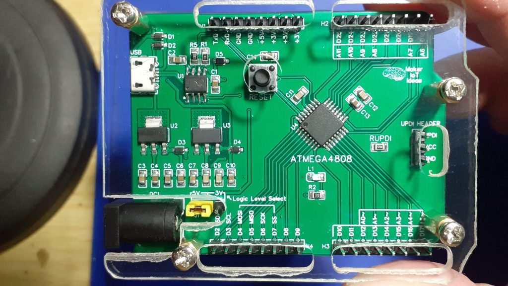
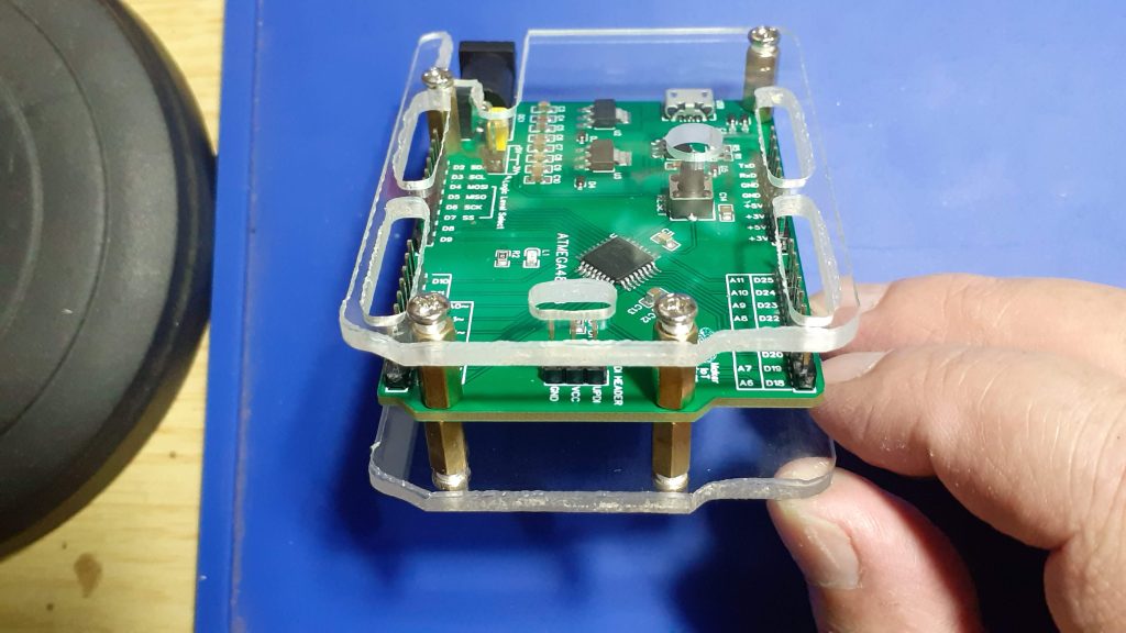

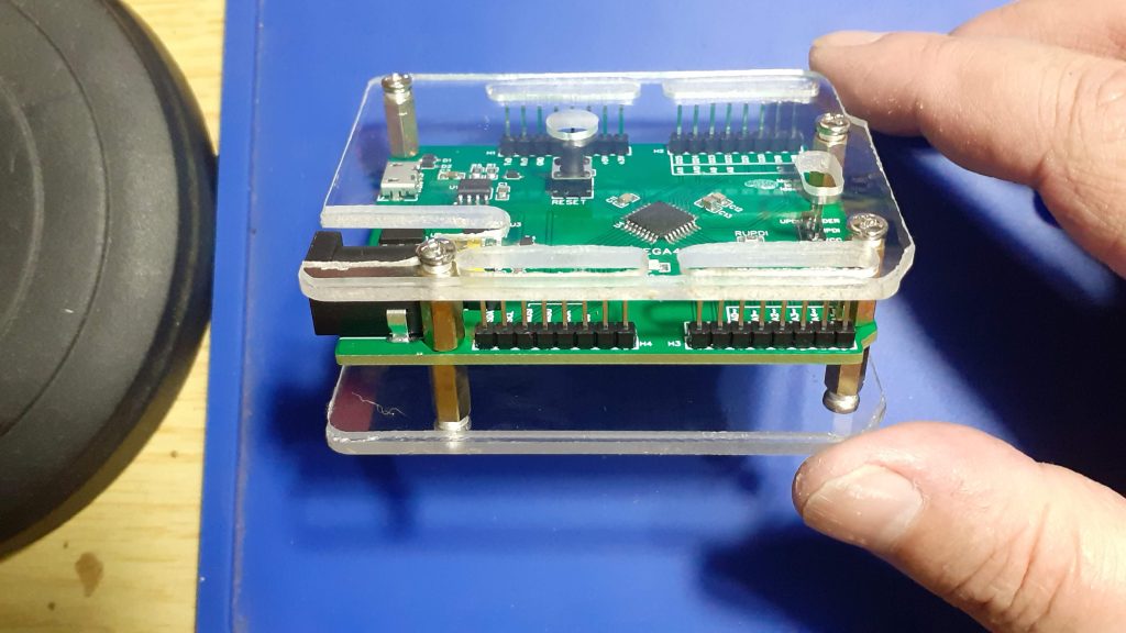
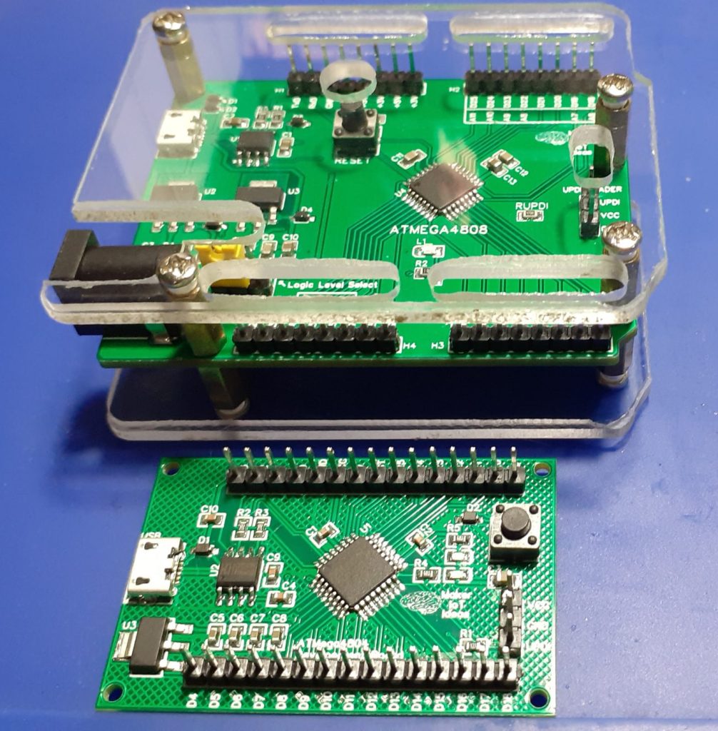


ATMEGA4808 Development Card in Arduino Form Factor
*PCBWay community is a sharing platform. We are not responsible for any design issues and parameter issues (board thickness, surface finish, etc.) you choose.
- Comments(0)
- Likes(1)
-
 Dmytro Skybin
Apr 02,2023
- 0 USER VOTES
- YOUR VOTE 0.00 0.00
- 1
- 2
- 3
- 4
- 5
- 6
- 7
- 8
- 9
- 10
- 1
- 2
- 3
- 4
- 5
- 6
- 7
- 8
- 9
- 10
- 1
- 2
- 3
- 4
- 5
- 6
- 7
- 8
- 9
- 10
- 1
- 2
- 3
- 4
- 5
- 6
- 7
- 8
- 9
- 10
 More by Jean Redelinghuys MakerIoT2020
-
 PCB_MCP23008_2023-10-08
MCP23008 BreakoutI designed this breakout to assist me during prototyping my next version of the “RP...
-
 PCB_XiaoRP2040-Mouse-REV2
Xiao RP2040 Joystick Mouse – revision 2.00Revision 1.0 of the ProjectOver the last few months, I hav...
-
 Multi Purpose IO Card
Multi-Purpose IO CardWhen we are working on a prototype, we always need access to pushbuttons, encod...
-
 Variable Voltage Power Module
Powering electronics projects are always challenging. This Variable vol...
Variable Voltage Power Module
Variable Voltage Power ModulePowering electronics projects are always challenging. This Variable vol...
-
 I2C Matrix Keypad
An I2C Matrix KeypadThe completed I2C Matrix KeypadIn a previous post this month I introduced my 4×4...
-
 ESP32-S Development Board, in "Arduino Uno" form factor
UPDATE 24/06/2023:This board now has a Hardware Revision 2.0 available. It is the same board but wit...
-
 W307186ASC94_Gerber_PCB_USB-Ports
USB Power Supply ModuleUSB Ports are quite handy to power all our day-to-day electronic devices, but...
-
 Atmega 328P based PWM controller Card
ATMega 328P Based PWM controller CardAs part of my recent ESP-12E I2C Base Board project, I designed...
-
 W307186ASC71_Gerber_PCB_ESP-Now Remote
Today we will look at the remote control unit for the Robotic Toy Car – Part 6.The project is close ...
-
 W307186ASV69_Gerber_PCB_Robot-Car-MCU-Board Prototype
In our last project, we started working on repurposing an old toy car. In this part, Robot Toy Car –...
-
 W307186ASV62_Gerber_PCB_DUAL-H-Bridge
by makeriot2020 on May 27, 2022Many of us have old toys laying around the house, they belong to ou...
-
 CAN-BUS Breakout
Breadboard Compatible CAN-BUS Breakout ModuleWhat is this:Some of us have already used the commonly ...
-
 RA-02 Breakout with Level converters
Breadboard and beginner-friendly RA-02 Breakout ModuleMost Makers and electronics enthusiasts may al...
-
 ATMEGA328P Module with integrated LoRa and CAN Bus
ATMEGA328P Module with integrated LoRa and CAN-BUSINTRODUCTIONIn my quest to perfect my LoRa telemet...
-
 Sx127x-Ra-02-Test-Module with ATMEGA328P-AU
SX127x LoRa/FSK/OOK Prototype Radio BoardI recently had a requirement to do some automation/telemetr...
-
 USB-ASP Programmer ATMEGA8
Build your own USB-ASP Programmer CloneBymakeriot2020 FEB 21, 2022 Arduino, ASP programmerUsing mor...
-
 ATTiny1616-LIGHT-Controller-with-CAN_B_PCB_ATTiny1616-LIGHT-Controller-with-C_2024-09-11
Assembly of the ATTiny1616 Can bus controller PCBThe Assembly of the ATTiny1616 Can Bus Controller P...
-
 ATTiny1616QFN-CAN-Remote-Neopixel-Ligh_PCB_ATTiny1616QFN-CAN-Remote-Neopixel-2024-09-11_2024-09-11
NeoPixel CAN-Bus Module with local controlAs part of my current project to add NeoPixels to the cabi...
-
-
AEL-2011 Power Supply Module
515 0 2 -
AEL-2011 50W Power Amplifier
474 0 2 -
-
-
Custom Mechanical Keyboard
691 0 0 -
Tester for Touch Screen Digitizer without using microcontroller
322 2 2 -
Audio reactive glow LED wristband/bracelet with NFC / RFID-Tags
306 0 1 -
-
-


