|
|
Openbuilds CAM |
|
|
|
Openbuilds Control |
|
|
|
LibreCad |
ATMEGA Tiny 1616 Development board - Complete
A complete ATTiny1616 Dev Solution
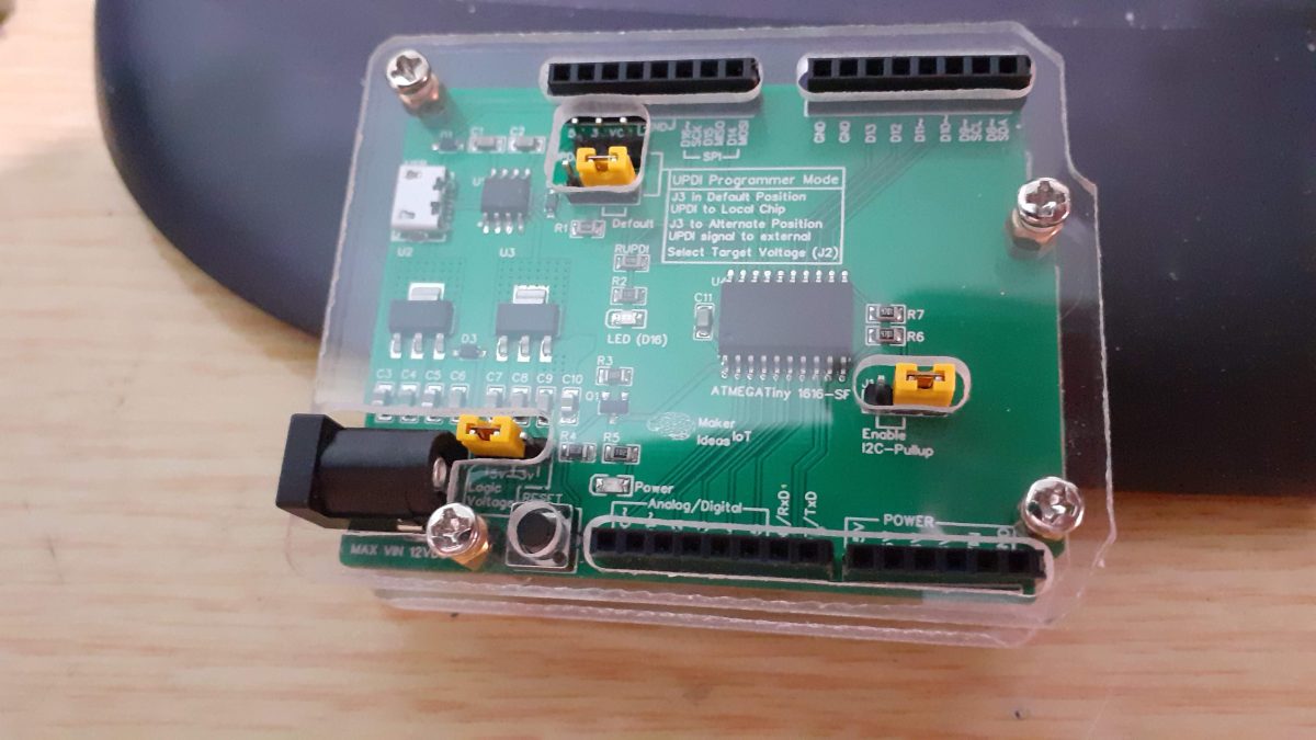
A few weeks ago, I started looking into alternative development solutions to reduce the effect of hard-to-get or more expensive-than-usual ATMEGA328 chips. One of the chips that I found to have potential was the ATTiny1616.
There seemed to be quite a lot of stock, and the prices were reasonable. Some additional hardware, like a dedicated UPDI programmer, had to be designed or bought, as the ATTiny1616 required UPDI to upload and flash code.
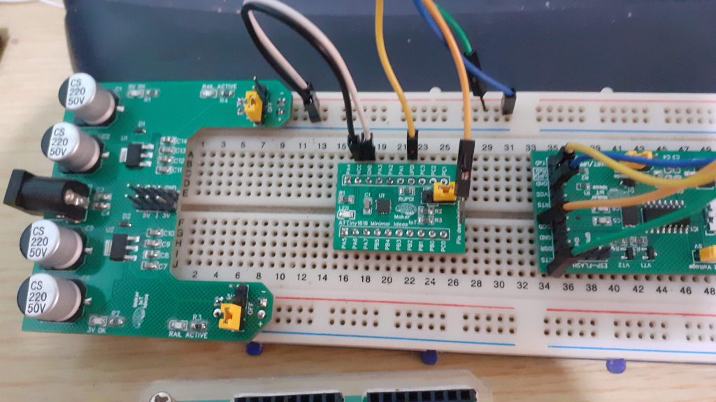 Setup to program ATTiny1616 Breakout Module – Power Module ( Left – Optional) ATTiny1616 Breakout – Center, UPDI programmer ( Right)
While the breakout worked flawlessly, I found the programming setup awkward and cumbersome. That was the cue to take the next step and create something that was easier to work with.
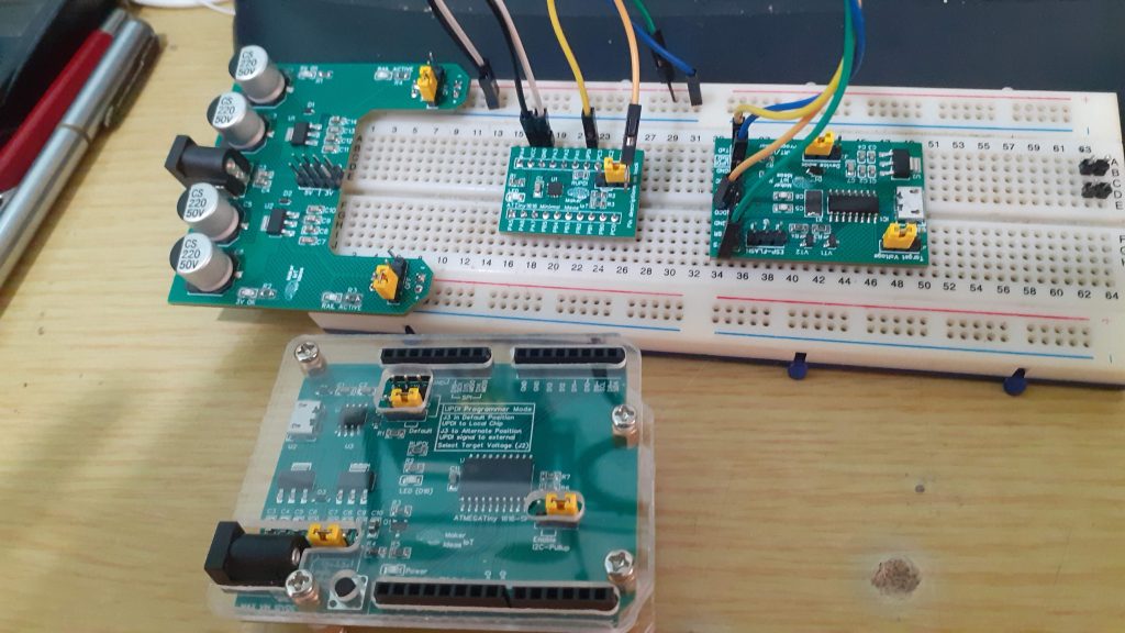 Old versus new. ATTiny1616 breakout module and programmer (Top) versus the all-new ATTiny1616 Development board, with all required hardware, included.
The new PCB offers a development cycle that is very similar to a standard Arduino UNO or Nano. Plug it into a USB port, write code, upload and repeat…
What is on the PCB?
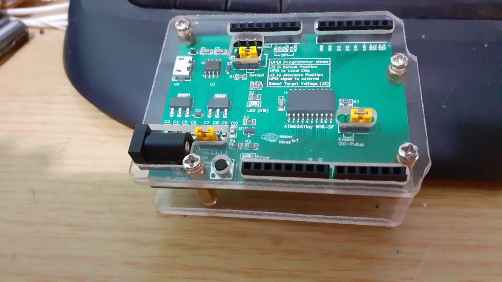
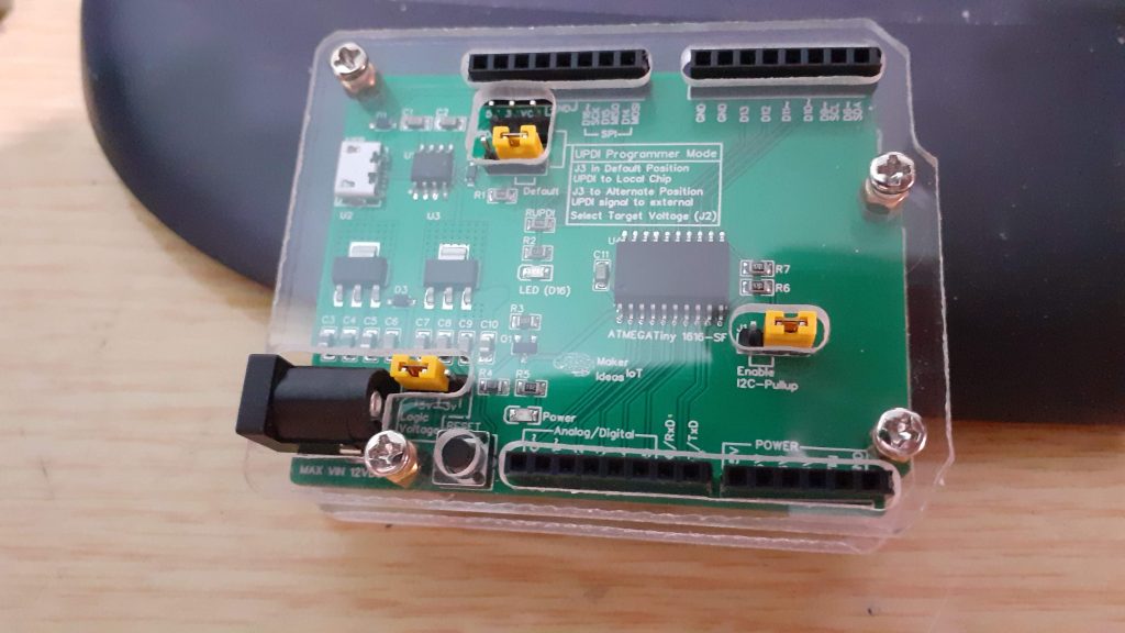
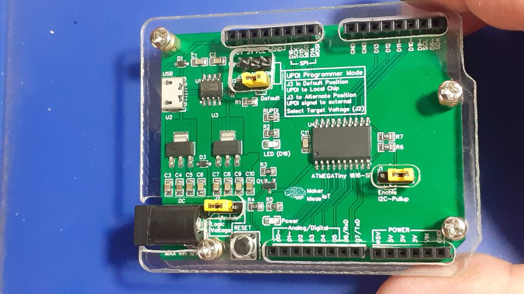 Top view- In acrylic Case
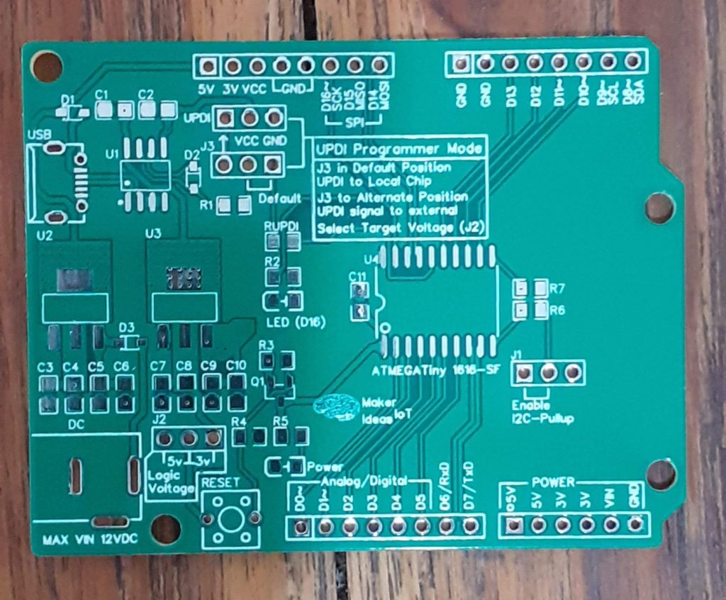
Starting at the Top Lefthand corner, we have a USB port, with a CH340N Chip. Note that this IS NOT A SERIAL UART. This is an integrated UPDI programmer, that can also be used in stand-alone mode to program external devices. (by moving J3 to the left, and using the UPDI header).
Below that is the power supply section, featuring two LDO Voltage regulators, providing 3.3v and 5v DC to the system. A DC barrel jack is included, to supply between 7v and 12v external DC voltage to the system. ( NOT to be used together with a USB cable)
Jumper J2 (next to the DC barrel jack) is used to switch the entire board logic level between 3.3v and 5v DC. A power indicator LED, as well as a standard user LED ( on pin D16), is also included. The rest of the PCB is dedicated to the ATTiny 1616 -SF, this time in a TSOP form factor. ( The original breakout used a QFN, but I realised that that may push away a lot of potential users, as QFN packages are quite difficult to solder without the proper equipment. A TSOP package is more accessible to everyone)
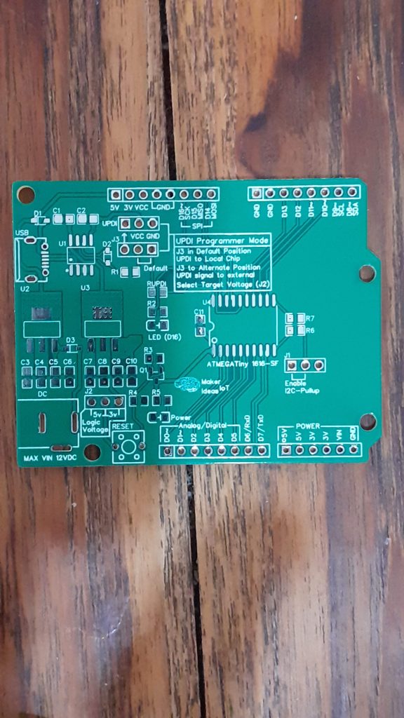
A total of 17 GPIO ports are available, of which each is labelled with an Arduino compatible label (D0 – D15), PWM ~ capable pins, and alternate functions like UART, SPI and I2C. Please Note that the onboard USB port IS NOT A UART
Features on the PCB – Summary
Reset Circuit with Push button – The ATTiny1616 shares its Reset pin with the UPDI programming pin. This will cause problems, requiring an HV UPDI programmer to fix. To resolve this issue, a reset circuit, comprising of a p-channel logic level Mosfet, that is wired to be constantly on, is connected via a suitable resistor on its gate, to a push-button to ground. pressing the button pulls the gate to ground, switching off the Mosfet, and thus the supply voltage to the chip, which equates to a power cycle reset. It is worth noting that the UPDI programming sequence also auto-resets the chip after every upload.
DC barrel jack for powering the device from an external source – 7v to 12DC
Onboard I2C pull-up resistors, selectable with a jumper ( J1)
Onboard UPDI programmer, which can also be used in stand-alone mode.
Selectable voltage logic level between 3.3v and 5.0v ( J2)
Assembly
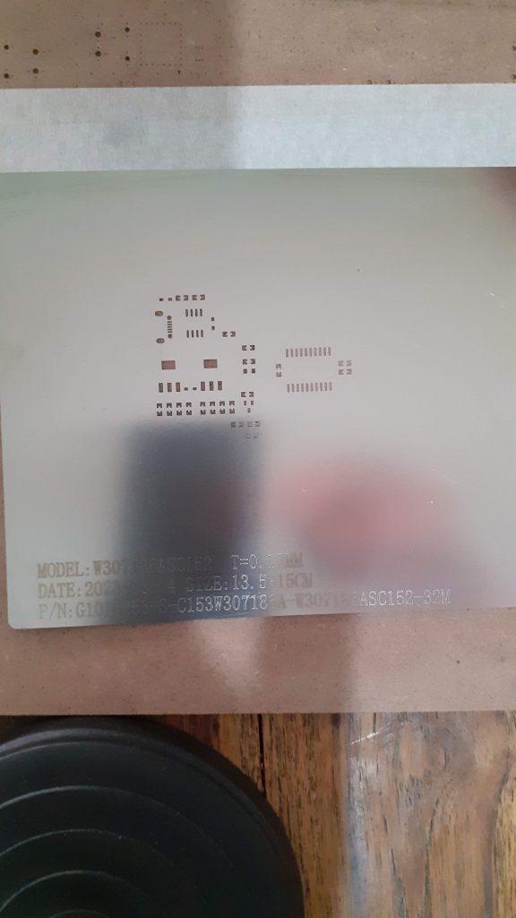
Stencil for Assembly
While this board can definitely be assembled completely by hand soldering, I chose to make use of a stencil, from PCBWay. This helps me by ensuring that the solder paste is applied in exactly the correct amount and place. Hot air or reflow soldering afterwards is a quick easy task. I prefer to use a hot plate to reflow the board, especially since it has a tiny USB connector, which can be quite a pain to solder with hot air, I won’t even go there with a normal soldering iron, as it is beyond what my eyes can handle at this stage.
Some more pictures

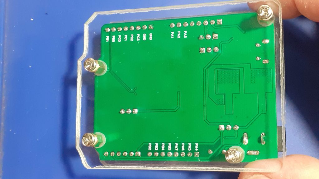
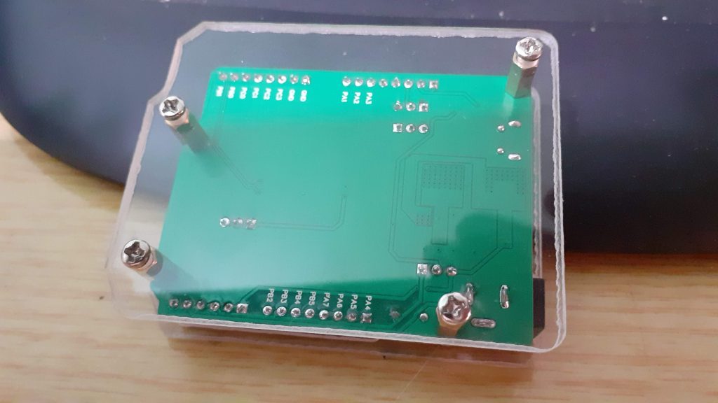

![]()
/*
  MODIFIED BLINK SKETCH FOR USE WITH ATTINY1616-SF DEV BOARD


  Required Core: megaTinyCore https://github.com/SpenceKonde/megaTinyCore

  Settings
  ATTiny 1616 WITHOUT OPTIBOOT
  16Mhz internal Osccilator
  SerialUPDI 230400 Baud or similar

  Remember to "UPLOAD USING Programmmer" ( Ctrl+Shift+U

*/
int LED = 16;

// the setup function runs once when you press reset or power the board
void setup() {

  pinMode(LED, OUTPUT);
  // Flash LED at startup

  for ( int k = 0; k < 2; k++)
  {
    digitalWrite(LED,!digitalRead(LED));
    delay(100);
  }
}

// the loop function runs over and over again forever
void loop() {
  // PWM test - breathing light
  for (int j=0; j < 2; j++ )
  {
    for (int k=0; k < 256; k++ )
    {
      analogWrite(LED,k);
      delay(10);
    }
    delay(400);
    for (int k=255; k> 0; k--)
    {
      analogWrite(LED,k);
      delay(10);
    }
  }
  delay(400);
  // now flash normally
  for ( int k = 0; k < 10; k++)
  {
    digitalWrite(LED,!digitalRead(LED));
    delay(500);
  }
  digitalWrite(LED,LOW);

}

ATMEGA Tiny 1616 Development board - Complete
*PCBWay community is a sharing platform. We are not responsible for any design issues and parameter issues (board thickness, surface finish, etc.) you choose.
- Comments(0)
- Likes(0)
- 0 USER VOTES
- YOUR VOTE 0.00 0.00
- 1
- 2
- 3
- 4
- 5
- 6
- 7
- 8
- 9
- 10
- 1
- 2
- 3
- 4
- 5
- 6
- 7
- 8
- 9
- 10
- 1
- 2
- 3
- 4
- 5
- 6
- 7
- 8
- 9
- 10
- 1
- 2
- 3
- 4
- 5
- 6
- 7
- 8
- 9
- 10
 More by Jean Redelinghuys MakerIoT2020
-
 PCB_MCP23008_2023-10-08
MCP23008 BreakoutI designed this breakout to assist me during prototyping my next version of the “RP...
-
 PCB_XiaoRP2040-Mouse-REV2
Xiao RP2040 Joystick Mouse – revision 2.00Revision 1.0 of the ProjectOver the last few months, I hav...
-
 Multi Purpose IO Card
Multi-Purpose IO CardWhen we are working on a prototype, we always need access to pushbuttons, encod...
-
 Variable Voltage Power Module
Powering electronics projects are always challenging. This Variable vol...
Variable Voltage Power Module
Variable Voltage Power ModulePowering electronics projects are always challenging. This Variable vol...
-
 I2C Matrix Keypad
An I2C Matrix KeypadThe completed I2C Matrix KeypadIn a previous post this month I introduced my 4×4...
-
 ESP32-S Development Board, in "Arduino Uno" form factor
UPDATE 24/06/2023:This board now has a Hardware Revision 2.0 available. It is the same board but wit...
-
 W307186ASC94_Gerber_PCB_USB-Ports
USB Power Supply ModuleUSB Ports are quite handy to power all our day-to-day electronic devices, but...
-
 Atmega 328P based PWM controller Card
ATMega 328P Based PWM controller CardAs part of my recent ESP-12E I2C Base Board project, I designed...
-
 W307186ASC71_Gerber_PCB_ESP-Now Remote
Today we will look at the remote control unit for the Robotic Toy Car – Part 6.The project is close ...
-
 W307186ASV69_Gerber_PCB_Robot-Car-MCU-Board Prototype
In our last project, we started working on repurposing an old toy car. In this part, Robot Toy Car –...
-
 W307186ASV62_Gerber_PCB_DUAL-H-Bridge
by makeriot2020 on May 27, 2022Many of us have old toys laying around the house, they belong to ou...
-
 CAN-BUS Breakout
Breadboard Compatible CAN-BUS Breakout ModuleWhat is this:Some of us have already used the commonly ...
-
 RA-02 Breakout with Level converters
Breadboard and beginner-friendly RA-02 Breakout ModuleMost Makers and electronics enthusiasts may al...
-
 ATMEGA328P Module with integrated LoRa and CAN Bus
ATMEGA328P Module with integrated LoRa and CAN-BUSINTRODUCTIONIn my quest to perfect my LoRa telemet...
-
 Sx127x-Ra-02-Test-Module with ATMEGA328P-AU
SX127x LoRa/FSK/OOK Prototype Radio BoardI recently had a requirement to do some automation/telemetr...
-
 USB-ASP Programmer ATMEGA8
Build your own USB-ASP Programmer CloneBymakeriot2020 FEB 21, 2022 Arduino, ASP programmerUsing mor...
-
 ATTiny1616-LIGHT-Controller-with-CAN_B_PCB_ATTiny1616-LIGHT-Controller-with-C_2024-09-11
Assembly of the ATTiny1616 Can bus controller PCBThe Assembly of the ATTiny1616 Can Bus Controller P...
-
 ATTiny1616QFN-CAN-Remote-Neopixel-Ligh_PCB_ATTiny1616QFN-CAN-Remote-Neopixel-2024-09-11_2024-09-11
NeoPixel CAN-Bus Module with local controlAs part of my current project to add NeoPixels to the cabi...
-
-
mammoth-3D SLM Voron Toolhead – Manual Drill & Tap Edition
140 0 0 -
-
AEL-2011 Power Supply Module
653 0 2 -
AEL-2011 50W Power Amplifier
567 0 2 -
-
-
Custom Mechanical Keyboard
769 0 0 -
Tester for Touch Screen Digitizer without using microcontroller
395 2 2 -
Audio reactive glow LED wristband/bracelet with NFC / RFID-Tags
363 0 1 -
-


