ATTiny202 Minimal breakout
Get Started with the ATMegaTiny202
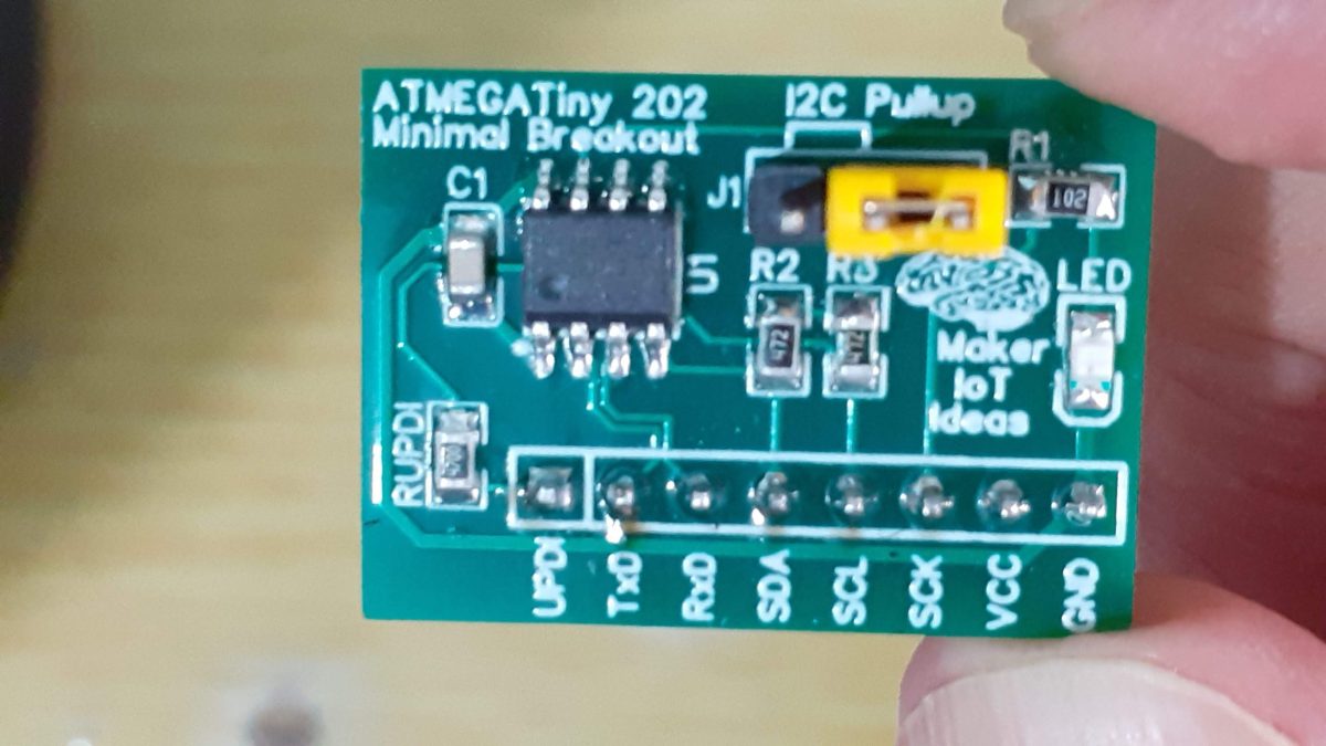
As I have hinted in my recent two posts about UPDI programmers, I am currently looking for a solution to replace the ATMEGA328P chip used in standard Arduino devices, like the UNO and NANO.
The global chip shortage seems to be still hitting hard, with these devices (Arduino UNO, NANO), and even bare chips being quite hard to get hold of, and when you do, they are quite more expensive than they used to be.
This sent me on a new journey, to find a new chip, that is easy to use, inexpensive, and easy to get hold of. I have found 3 of these chips, starting today with the ATMEGATiny202,
 ATMEGATiny 202
The ATtiny202 is a microcontroller using the 8-bit AVR® processor with a hardware multiplier, running up to 20 MHz and 2 KB Flash, 128B SRAM, and 64 bytes of EEPROM in an 8-pin package. The series uses the latest technologies from Microchip with a flexible and low-power architecture, including Event System and SleepWalking, accurate analog features and advanced peripherals.
With only 8 pins, of which we can practically use only 5 ( 6 if you have an HV UPDI programmer ). This makes it a desirable solution for small projects, with its current price of about 0.59 USD per chip ( SOIC8 PACKAGE, Element14 ) , not breaking the bank either. Not needing an external oscillator, and requiring only a single 100nf bypass capacitor, (not counting the UPDI resistor) it can indeed be a very very cheap way to get a project done… Providing of course that you don’t need a lot of Program memory or RAM, and are not trying to do too many super fancy or complicated things.
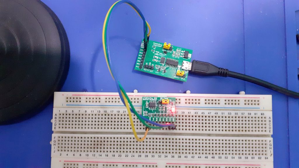
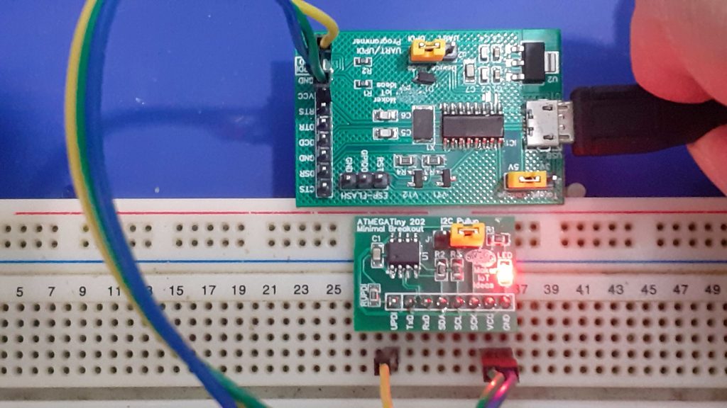 ATMegaTiny202 Minimal Breakout, on Breadboard with MakerIoT2020 Multipurpose Uart/UPDI Programmer
The wide operating voltage of 1.8v right up to 5.5v also makes it quite flexible.
My initial prototype
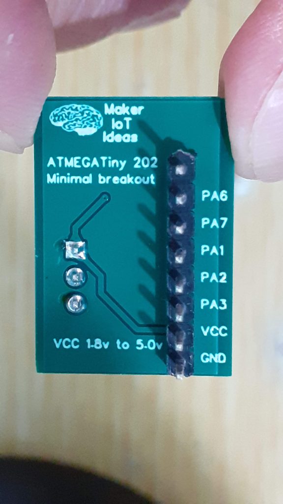
Getting started with a new chip is also a bit of an issue, as there are many new things to learn, recommended supporting components, and also firmware and cores that need to be installed. I have decided to build a quick breadboard-capable PCB, with all 8 pins broken out in a single row, feel free to change the straight header pins to a 90-degree version at your convenience, it takes up even less space that way.
The PCB contains only the bare minimum required components for the chip to function, but I also added onboard I2C pullup resistors, with a jumper to select them. ( Most I2C modules usually have these already, but as I build most of my own breakouts myself, I decided to include these).
A single LED brightens things up a bit, connected to pin PA3, making it possible to run a blink sketch…
The rest of the components include a 100nf bypass capacitor and the very important 470ohm UPDI resistor.
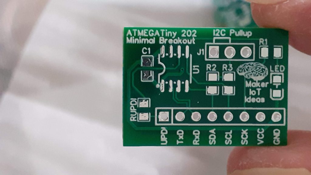 PCB Top view, unpopulated
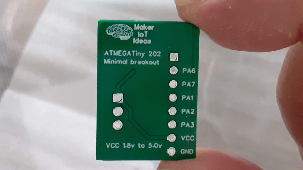 PCB Bottom, unpopulated
Programming the board
I use the Arduino IDE quite a lot, and also assume that most makers and hobbyists out there will do the same. Luckily we have access to a special Arduino core, the megaTinyCore, that provides us with all we need to program this tiny little chip, provided of course that you have a UPDI programmer.
See the link above for installation instructions, as well as detailed documentation. Replicating all of that here will be an unnecessary task, as the author of the core, SpenceKonde, has already done an excellent job.
One very important thing to note on this board is that there is NO RESET PIN.
You have to manually cycle power to it, but, I have found that initiating a UPDI upload to a running chip works every time, and makes it unnecessary…
The reason for the lack of a reset pin lies in the fact that the reset is shared with the UPDI pin, and enabling it, will rob you of the UPDI functionality UNLESS you have an HV UPDI programmer, which at this time seems to be hard to find/expensive item ( Hope to build my own soon). Once again, see the above link to the core documentation for the full information on the reset pin issue…
I can not stress enough how important it is to sit down and READ the core documentation, with attention, before doing anything with this chip and core. you will learn a lot, about the chip, new features, possible problems, and how to avoid them, and also some customised GPIO functions etc…
Schematic
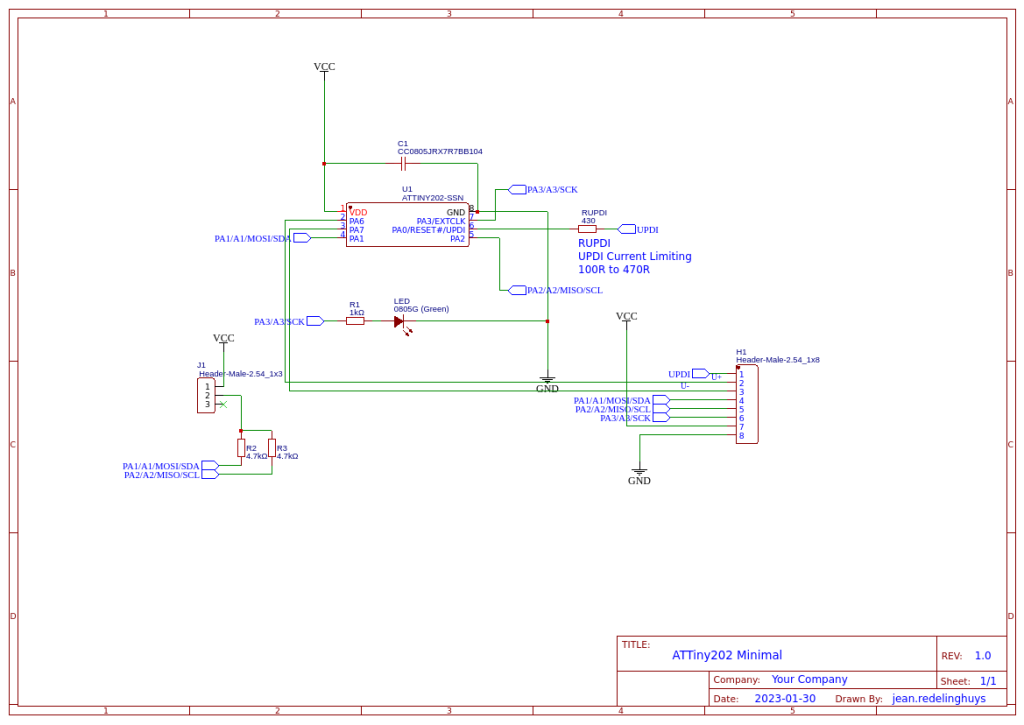
Manufacturing
 PCB Layout
The PCB is a double-layer PCB, with the signal traces on the top layer, power traces, and the ground-plane, on the bottom layer. the Dimensions are 26.035mm x 18.669m. All SMD components are 0805. This board does not need a stencil for assembly and can be hand or hot-air soldered in a few minutes with no problems.
Picture Gallery
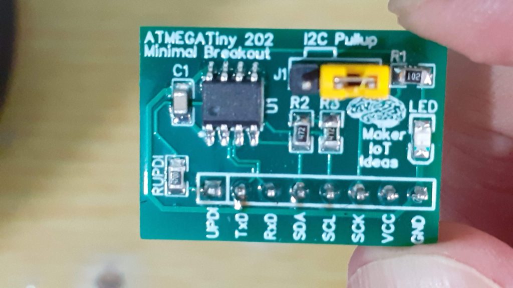 ATTiny202 Minimal breakout. All you need to get started, just add a UPDI programmer, Arduino IDE, and the MegaTinyCore…


![]() Author makeriot2020Posted on February 22, 2023Categories Arduino, Electronics, PCBDesignTags Arduino, ATTiny202, Electronics Edit "Get Started with the ATMegaTiny202"
Author makeriot2020Posted on February 22, 2023Categories Arduino, Electronics, PCBDesignTags Arduino, ATTiny202, Electronics Edit "Get Started with the ATMegaTiny202"
/*
 This is the standard Arduino Blink sketch.
 LED_BUILTIN works fine, but you can also use 4, or PIN_PA3 as per megaTinyCore
 specifications.

*/

// the setup function runs once when you press reset or power the board
void setup() {
  // initialize digital pin LED_BUILTIN as an output.
  pinMode(LED_BUILTIN, OUTPUT);
}

// the loop function runs over and over again forever
void loop() {
  digitalWrite(LED_BUILTIN, HIGH);   // turn the LED on (HIGH is the voltage level)
  delay(1000);                       // wait for a second
  digitalWrite(LED_BUILTIN, LOW);    // turn the LED off by making the voltage LOW
  delay(1000);                       // wait for a second
}

ATTiny202 Minimal breakout
*PCBWay community is a sharing platform. We are not responsible for any design issues and parameter issues (board thickness, surface finish, etc.) you choose.
- Comments(0)
- Likes(0)
- 0 USER VOTES
- YOUR VOTE 0.00 0.00
- 1
- 2
- 3
- 4
- 5
- 6
- 7
- 8
- 9
- 10
- 1
- 2
- 3
- 4
- 5
- 6
- 7
- 8
- 9
- 10
- 1
- 2
- 3
- 4
- 5
- 6
- 7
- 8
- 9
- 10
- 1
- 2
- 3
- 4
- 5
- 6
- 7
- 8
- 9
- 10
 More by Jean Redelinghuys MakerIoT2020
-
 PCB_MCP23008_2023-10-08
MCP23008 BreakoutI designed this breakout to assist me during prototyping my next version of the “RP...
-
 PCB_XiaoRP2040-Mouse-REV2
Xiao RP2040 Joystick Mouse – revision 2.00Revision 1.0 of the ProjectOver the last few months, I hav...
-
 Multi Purpose IO Card
Multi-Purpose IO CardWhen we are working on a prototype, we always need access to pushbuttons, encod...
-
 Variable Voltage Power Module
Powering electronics projects are always challenging. This Variable vol...
Variable Voltage Power Module
Variable Voltage Power ModulePowering electronics projects are always challenging. This Variable vol...
-
 I2C Matrix Keypad
An I2C Matrix KeypadThe completed I2C Matrix KeypadIn a previous post this month I introduced my 4×4...
-
 ESP32-S Development Board, in "Arduino Uno" form factor
UPDATE 24/06/2023:This board now has a Hardware Revision 2.0 available. It is the same board but wit...
-
 W307186ASC94_Gerber_PCB_USB-Ports
USB Power Supply ModuleUSB Ports are quite handy to power all our day-to-day electronic devices, but...
-
 Atmega 328P based PWM controller Card
ATMega 328P Based PWM controller CardAs part of my recent ESP-12E I2C Base Board project, I designed...
-
 W307186ASC71_Gerber_PCB_ESP-Now Remote
Today we will look at the remote control unit for the Robotic Toy Car – Part 6.The project is close ...
-
 W307186ASV69_Gerber_PCB_Robot-Car-MCU-Board Prototype
In our last project, we started working on repurposing an old toy car. In this part, Robot Toy Car –...
-
 W307186ASV62_Gerber_PCB_DUAL-H-Bridge
by makeriot2020 on May 27, 2022Many of us have old toys laying around the house, they belong to ou...
-
 CAN-BUS Breakout
Breadboard Compatible CAN-BUS Breakout ModuleWhat is this:Some of us have already used the commonly ...
-
 RA-02 Breakout with Level converters
Breadboard and beginner-friendly RA-02 Breakout ModuleMost Makers and electronics enthusiasts may al...
-
 ATMEGA328P Module with integrated LoRa and CAN Bus
ATMEGA328P Module with integrated LoRa and CAN-BUSINTRODUCTIONIn my quest to perfect my LoRa telemet...
-
 Sx127x-Ra-02-Test-Module with ATMEGA328P-AU
SX127x LoRa/FSK/OOK Prototype Radio BoardI recently had a requirement to do some automation/telemetr...
-
 USB-ASP Programmer ATMEGA8
Build your own USB-ASP Programmer CloneBymakeriot2020 FEB 21, 2022 Arduino, ASP programmerUsing mor...
-
 ATTiny1616-LIGHT-Controller-with-CAN_B_PCB_ATTiny1616-LIGHT-Controller-with-C_2024-09-11
Assembly of the ATTiny1616 Can bus controller PCBThe Assembly of the ATTiny1616 Can Bus Controller P...
-
 ATTiny1616QFN-CAN-Remote-Neopixel-Ligh_PCB_ATTiny1616QFN-CAN-Remote-Neopixel-2024-09-11_2024-09-11
NeoPixel CAN-Bus Module with local controlAs part of my current project to add NeoPixels to the cabi...
-
-
mammoth-3D SLM Voron Toolhead – Manual Drill & Tap Edition
174 0 0 -
-
AEL-2011 Power Supply Module
692 0 2 -
AEL-2011 50W Power Amplifier
589 0 2 -
-
-
Custom Mechanical Keyboard
788 0 0 -
Tester for Touch Screen Digitizer without using microcontroller
411 2 2 -
Audio reactive glow LED wristband/bracelet with NFC / RFID-Tags
376 0 1 -
-


