


Breadboard friendly MCP23017 Breakout board, TSSOP28 version
Redesigning my MCP23017 breakout

In a previous post, I designed a breadboard-friendly MCP23017 breakout module. A few months have passed, and after using the module for a while, some issues came to light…
In this post, I will show you how I have fixed those issues, and then I can continue testing/using the new generation prototype, and hopefully, it can become the final revision of this project.
Old Versus New
Let us start by looking at the old and new PCB designs…
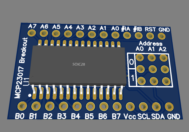
Old style MCP23017 Breakout – Top view
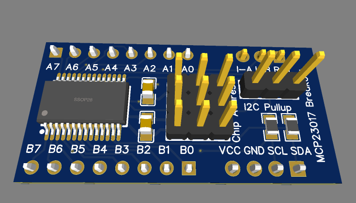
New style MCP23017 Breakout – Top view
There will not be a lot of obvious differences at first, but if we look closely, here are the changes:
– In the old version, due to the size of the SOIC28 footprint, I had to place the bypass capacitors, as well as I2C pullup resistors on the bottom layer of the PCB.
The new design, using the more readily available ( at least where I live) SSOP28 footprint, leaves enough space for these components on the top layer, thus resulting in a mostly single-layer layout, with only a few tracks on the bottom layer.
I2C pull-up resistors can now be controlled by a jumper, enabling or disabling them completely… This helps when adding a few devices to the I2C bus, and rather having the pull-up’s close to the MCU ( as is generally recommended anyway )
Other cosmetic changes involve the separation of the data ports (A and B) from the interrupts, reset, Vcc and ground pins. On initial testing of this on a breadboard, it makes using the device a bit easier, and access to the io pins faster. ( In my biased opinion anyway )
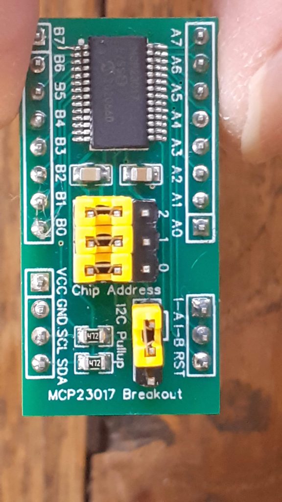
MCP23017 Breakout – New version
Pinouts and connections
I have tried to make all the connections easy to find and use, with the IO ports ( A and B) on opposite sides of the breakout, Numbered A7 to A0 on the top, and B7 to B0 on the bottom.
VCC, GND, SCL and SDA are on a separate 4-way header pin, with the two interrupt pins (I-A and I-B) together with the reset (RST) pin on a 3-way header opposite the power and signal header..
Addressing pins are in the centre of the PCB, marked with a 2 1 0 ( for AD2, AD1, and AD0 respectively), Jumpers to the bottom ( towards port B) pull the pins to ground, where the opposite side will pull the address pins high.
To the right of that, another 3-way jumper enables or disables the I2C pull-resistors on the module, which in this case is set at 4k7.
/*
Code example for MCP23017

Please note that sometimes, copy pasting code can result in strange behavious in the Arduino IDE.
If this happens, please type the code manually to eliminate any "hidden" characters, placed by the browser.

*/


// pins 15~17 to GND, I2C bus address is 0x20
#include "Wire.h"
void setup()
{
 Wire.begin(); // wake up I2C bus
// set I/O pins to outputs
 Wire.beginTransmission(0x20);
 Wire.write(0x00); // IODIRA register
 Wire.write(0x00); // set all of port A to outputs
 Wire.endTransmission();
Wire.beginTransmission(0x20);
 Wire.write(0x01); // IODIRB register
 Wire.write(0x00); // set all of port B to outputs
 Wire.endTransmission();
}
void binaryCount()
{
 for (byte a=0; a<256; a++)
 {
 Wire.beginTransmission(0x20);
 Wire.write(0x12); // GPIOA
 Wire.write(a); // port A
 Wire.endTransmission();
Wire.beginTransmission(0x20);
 Wire.write(0x13); // GPIOB
 Wire.write(a); // port B
 Wire.endTransmission();
 }
}
void loop()
{
 binaryCount();
 delay(500);
}

Breadboard friendly MCP23017 Breakout board, TSSOP28 version
*PCBWay community is a sharing platform. We are not responsible for any design issues and parameter issues (board thickness, surface finish, etc.) you choose.


- Comments(0)
- Likes(1)
More by Jean Redelinghuys MakerIoT2020
-
 PCB_MCP23008_2023-10-08
MCP23008 BreakoutI designed this breakout to assist me during prototyping my next version of the “RP...
PCB_MCP23008_2023-10-08
MCP23008 BreakoutI designed this breakout to assist me during prototyping my next version of the “RP...
-
 PCB_XiaoRP2040-Mouse-REV2
Xiao RP2040 Joystick Mouse – revision 2.00Revision 1.0 of the ProjectOver the last few months, I hav...
PCB_XiaoRP2040-Mouse-REV2
Xiao RP2040 Joystick Mouse – revision 2.00Revision 1.0 of the ProjectOver the last few months, I hav...
-
 Multi Purpose IO Card
Multi-Purpose IO CardWhen we are working on a prototype, we always need access to pushbuttons, encod...
Multi Purpose IO Card
Multi-Purpose IO CardWhen we are working on a prototype, we always need access to pushbuttons, encod...
-
 Variable Voltage Power Module
Powering electronics projects are always challenging. This Variable vol...
Variable Voltage Power Module
Variable Voltage Power ModulePowering electronics projects are always challenging. This Variable vol...
-
 I2C Matrix Keypad
An I2C Matrix KeypadThe completed I2C Matrix KeypadIn a previous post this month I introduced my 4×4...
I2C Matrix Keypad
An I2C Matrix KeypadThe completed I2C Matrix KeypadIn a previous post this month I introduced my 4×4...
-
 ESP32-S Development Board, in "Arduino Uno" form factor
UPDATE 24/06/2023:This board now has a Hardware Revision 2.0 available. It is the same board but wit...
ESP32-S Development Board, in "Arduino Uno" form factor
UPDATE 24/06/2023:This board now has a Hardware Revision 2.0 available. It is the same board but wit...
-
 W307186ASC94_Gerber_PCB_USB-Ports
USB Power Supply ModuleUSB Ports are quite handy to power all our day-to-day electronic devices, but...
W307186ASC94_Gerber_PCB_USB-Ports
USB Power Supply ModuleUSB Ports are quite handy to power all our day-to-day electronic devices, but...
-
 Atmega 328P based PWM controller Card
ATMega 328P Based PWM controller CardAs part of my recent ESP-12E I2C Base Board project, I designed...
Atmega 328P based PWM controller Card
ATMega 328P Based PWM controller CardAs part of my recent ESP-12E I2C Base Board project, I designed...
-
 W307186ASC71_Gerber_PCB_ESP-Now Remote
Today we will look at the remote control unit for the Robotic Toy Car – Part 6.The project is close ...
W307186ASC71_Gerber_PCB_ESP-Now Remote
Today we will look at the remote control unit for the Robotic Toy Car – Part 6.The project is close ...
-
 W307186ASV69_Gerber_PCB_Robot-Car-MCU-Board Prototype
In our last project, we started working on repurposing an old toy car. In this part, Robot Toy Car –...
W307186ASV69_Gerber_PCB_Robot-Car-MCU-Board Prototype
In our last project, we started working on repurposing an old toy car. In this part, Robot Toy Car –...
-
 W307186ASV62_Gerber_PCB_DUAL-H-Bridge
by makeriot2020 on May 27, 2022Many of us have old toys laying around the house, they belong to ou...
W307186ASV62_Gerber_PCB_DUAL-H-Bridge
by makeriot2020 on May 27, 2022Many of us have old toys laying around the house, they belong to ou...
-
 CAN-BUS Breakout
Breadboard Compatible CAN-BUS Breakout ModuleWhat is this:Some of us have already used the commonly ...
CAN-BUS Breakout
Breadboard Compatible CAN-BUS Breakout ModuleWhat is this:Some of us have already used the commonly ...
-
 RA-02 Breakout with Level converters
Breadboard and beginner-friendly RA-02 Breakout ModuleMost Makers and electronics enthusiasts may al...
RA-02 Breakout with Level converters
Breadboard and beginner-friendly RA-02 Breakout ModuleMost Makers and electronics enthusiasts may al...
-
 ATMEGA328P Module with integrated LoRa and CAN Bus
ATMEGA328P Module with integrated LoRa and CAN-BUSINTRODUCTIONIn my quest to perfect my LoRa telemet...
ATMEGA328P Module with integrated LoRa and CAN Bus
ATMEGA328P Module with integrated LoRa and CAN-BUSINTRODUCTIONIn my quest to perfect my LoRa telemet...
-
 Sx127x-Ra-02-Test-Module with ATMEGA328P-AU
SX127x LoRa/FSK/OOK Prototype Radio BoardI recently had a requirement to do some automation/telemetr...
Sx127x-Ra-02-Test-Module with ATMEGA328P-AU
SX127x LoRa/FSK/OOK Prototype Radio BoardI recently had a requirement to do some automation/telemetr...
-
 USB-ASP Programmer ATMEGA8
Build your own USB-ASP Programmer CloneBymakeriot2020 FEB 21, 2022 Arduino, ASP programmerUsing mor...
USB-ASP Programmer ATMEGA8
Build your own USB-ASP Programmer CloneBymakeriot2020 FEB 21, 2022 Arduino, ASP programmerUsing mor...
-
 ATTiny1616-LIGHT-Controller-with-CAN_B_PCB_ATTiny1616-LIGHT-Controller-with-C_2024-09-11
Assembly of the ATTiny1616 Can bus controller PCBThe Assembly of the ATTiny1616 Can Bus Controller P...
ATTiny1616-LIGHT-Controller-with-CAN_B_PCB_ATTiny1616-LIGHT-Controller-with-C_2024-09-11
Assembly of the ATTiny1616 Can bus controller PCBThe Assembly of the ATTiny1616 Can Bus Controller P...
-
 ATTiny1616QFN-CAN-Remote-Neopixel-Ligh_PCB_ATTiny1616QFN-CAN-Remote-Neopixel-2024-09-11_2024-09-11
NeoPixel CAN-Bus Module with local controlAs part of my current project to add NeoPixels to the cabi...
ATTiny1616QFN-CAN-Remote-Neopixel-Ligh_PCB_ATTiny1616QFN-CAN-Remote-Neopixel-2024-09-11_2024-09-11
NeoPixel CAN-Bus Module with local controlAs part of my current project to add NeoPixels to the cabi...
-
-
mammoth-3D SLM Voron Toolhead – Manual Drill & Tap Edition
223 0 0 -
-
-
-
Tester for Touch Screen Digitizer without using microcontroller
446 2 2 -
Audio reactive glow LED wristband/bracelet with NFC / RFID-Tags
397 0 1 -
-


