|
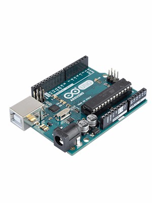
ARDUINO UNO REV3 |
x 1 | |

|
HC-SR04OSEPP Electronics
|
x 1 | |

|
push button kit-
|
x 1 | |
|
|
LCD 16x2 DisplayLCD 16x2 Display
|
x 1 |

|
arduino IDEArduino
|
Educational Robot for Children
All areas of knowledge such as sciences, human or biological, have their respective importance. With this, the teacher responsible for transmitting his knowledge has to keep in mind how important his mission is.
In the teaching of educational robotics this also has to be considered, because for each age group in which it is desired to reach, it is necessary to use appropriate tools and methodologies.
Educational robotics can reach and address various subjects, intertwining them with the concepts we learn in school. An example is learning the vowels of the alphabet.
Through some electronic devices, it is possible to encourage and motivate the learning of vowels, thus reaching the audience of children who are at this stage of learning, and with that, making learning more dynamic and fun.
In this way, it is possible to assimilate the assembly of a simple robot with its respective control, using some electronic devices such as the ultrasonic sensor, the LCD display and some buttons.
As the prototype would be a didactic model, the ideal is to use an Arduino development platform to control its operation. Figure 1 illustrates a prototype of an educational robot using some electronic devices.
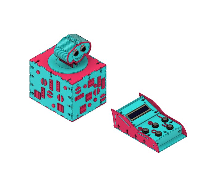
In the development of this educational robot, an ultrasonic sensor, an LCD display, 5 buttons, a 2 Poles Seesaw Switch and the Arduino uno were used.
In this context, the Arduino will be responsible for triggering a sound corresponding to the letter in which the button is pressed by the user, and then visually displaying it on the LCD display.
Therefore, through this article, together with PCBWay you will learn:
- Knowing the structure of the Educational Robot using the HC-SR04 ultrasonic sensor, the 16x2 LCD Display, a Kcd1-101 2 Poles Seesaw Key (On-Off) the Push Button and the Arduino Uno;
- To analyze the fixing of the mechanical structure of the robot case by means of screw, nut and fittings;
- To understand the importance of each part of the robot structure for the whole project.
- Understanding the working logic of the Educational Robot.
Now, we will start the complete presentation of the development of the Educational Robot project.
Project Development Methodology
This project consists of presenting a didactic robot using the ultrasonic sensor, and also the assembly of its mechanical structure.
The project basically consists of a physical structure similar to a box, which is the robot's body, and a control. In the robot's body are the arduino, the ultrasonic sensor and the sound box that will be responsible for informing the letter that was pressed by the user.
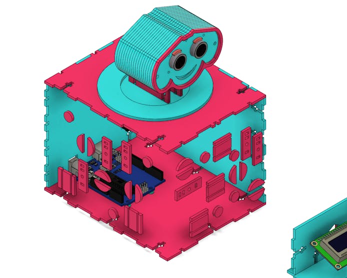
The Control is responsible for detecting the letter that was typed and sending the signal to the Arduino. Figure 2 illustrates the internal region of the robot.
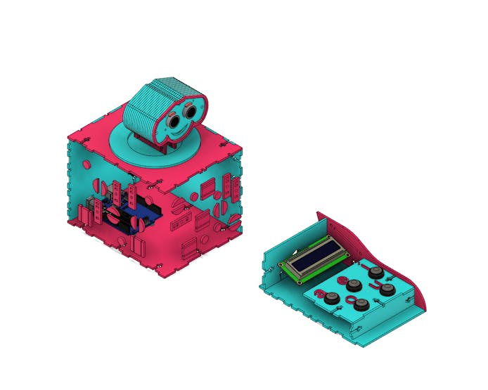
In the internal structure it is possible to observe the Arduino and the seesaw switch on the back of the robot's body, already in the control, as it will send the signal through connections to the arduino, it only has the space for the wires.
It is available for download and you can earn 10 PCBWay units.
Follow the step by step to access the full project and earn 10 free PCBWay units.
Access the following link and create your account on the PCBWay website;
Upload the gerber file in PCBWay website.
At some points it is also possible to observe some tears, where the spare parts of the sides and surfaces of the prototype will be fitted.
Fittings sized for M3 nuts and screws were designed for fixing the structure.
The M3 screw has an ideal size for this type of project, because a size above or below this size could increase the weight of the prototype unnecessarily, or make it more fragile, respectively. Figure 3 illustrates the inner and upper surfaces of the robot.
The robot has a structure on its neck that allows it to rotate its head around an axis.
The structure is formed by a circular part that is connected to the inner region of the upper surface of the robot.
Then, another circular piece was modeled that is on the upper surface, but with a small gap in order to facilitate its displacement around its own axis. And finally, there is another circular piece in the upper region of the surface in question.
At the end, the neck is fixed to the rotation frame by two screws. The combination of these parts allows the robot's neck to move.
Figure 4 illustrates the mechanism described.

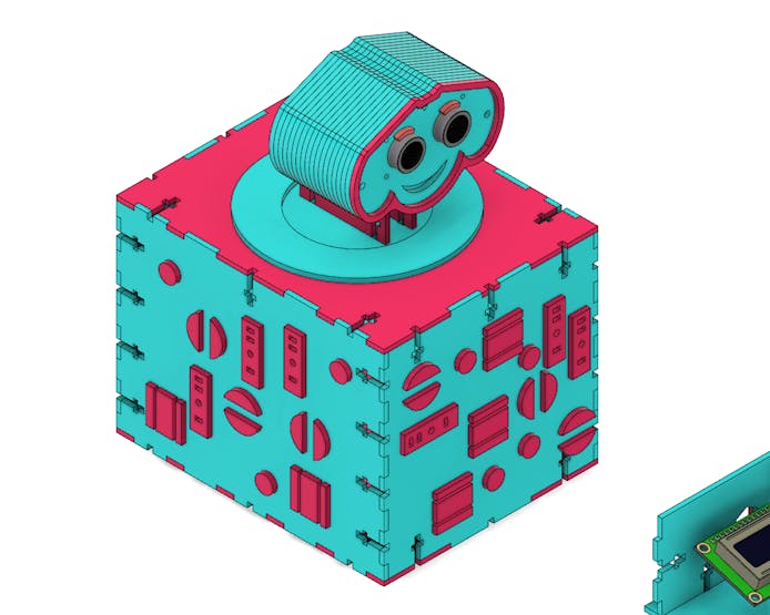
The robot has some embossed details to give the appearance of spare parts, giving the impression of robot parts. Figure 5 illustrates the arrangement of these parts on the external surfaces of the robot.
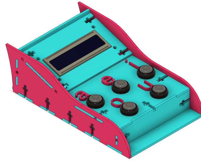
The robot control basically consists of a 16x2 LCD display and 5 Push Buttons.
It also has the 5 letters representing each button. Each vowel letter has a button, and when the user presses the corresponding button, the signal will be sent to the arduino uno, and the display will indicate the letter typed, making it even easier to learn both robotics and vowels.
Figure 6 illustrates the Educational Robot control.
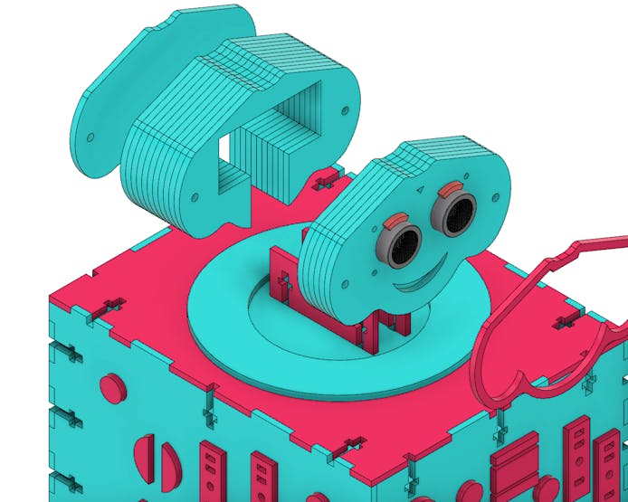
The face of the educational robot is basically composed of three parts: the region grouped with the ultrasonic sensor, the one used to separate the wires and not leave them exposed in relation to the first part, and the third, which is the cover of the rear region of the head.
The first two have a few extra layers to add thickness (these layers can be connected using glue), and they all connect via an M3 screw that connects them all.
In addition to these, the robot's face still has a contour and eyebrows to make the face more friendly.
Figure 7 illustrates the face of the Educational Robot.
For the fixation of the ultrasonic sensor, a structure was modeled to fix it in front of the robot, shown in the previous figure, where it will be connected by 4 standard screws of the sensor itself, with their respective nuts.
Figure 8 illustrates the position of the ultrasonic sensor on the educational robot.
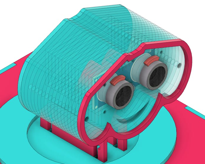
The ultrasonic sensor was placed with the intention of reacting according to the presence of the user. Both the contour of the face and the eyebrows were shaped to highlight the expression of the educational robot.
The Arduino is basically responsible for two purposes: to process the signal coming from the ultrasonic sensor and the Push Buttons, and to make the necessary settings to send the signal to the LCD display and for the sound that will reproduce the letters.
The Arduino was positioned in the internal rear region of the robot, in order to facilitate the programming developed and its possible changes, being necessary only to fit the power cables and the USB communication.
Next to the arduino connections, a seesaw switch was also placed to power and de-energize the circuit.
Figure 9 illustrates the position of the arduino and seesaw connections on the educational robot.
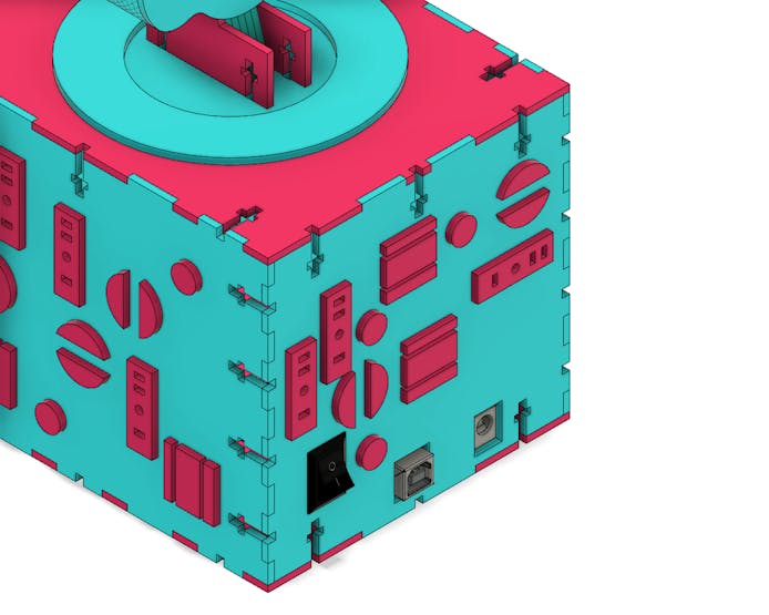
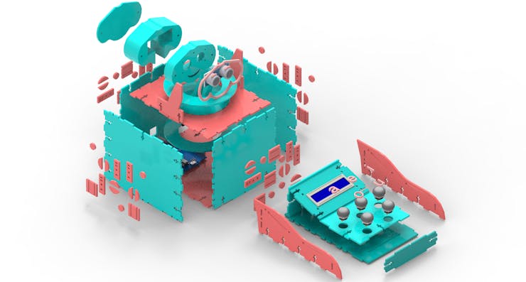
Figure 10 illustrates the entire structure of the Educational Robot in exploded perspective of the main parts in a rendered image.
Next, we have the programming logic for the project.
Project programming logic
In the following, I will explain the step by step to building the logic of this fun game for children.
#include <SoftwareSerial.h>

#define ARDUINO_RX 5  //should connect to TX of the Serial MP3 Player module
#define ARDUINO_TX 6  //connect to RX of the module

SoftwareSerial mp3(ARDUINO_RX, ARDUINO_TX);

static int8_t Send_buf[8] = {0}; // Buffer for Send commands.  // BETTER LOCALLY
static uint8_t ansbuf[10] = {0}; // Buffer for the answers.    // BETTER LOCALLY

String mp3Answer;           // Answer from the MP3.

String sanswer(void);
String sbyte2hex(uint8_t b);

/************ Command byte **************************/
#define CMD_NEXT_SONG     0X01  // Play next song.
#define CMD_PREV_SONG     0X02  // Play previous song.
#define CMD_PLAY_W_INDEX  0X03
#define CMD_VOLUME_UP     0X04
#define CMD_VOLUME_DOWN   0X05
#define CMD_SET_VOLUME    0X06

#define CMD_SNG_CYCL_PLAY 0X08  // Single Cycle Play.
#define CMD_SEL_DEV       0X09
#define CMD_SLEEP_MODE    0X0A
#define CMD_WAKE_UP       0X0B
#define CMD_RESET         0X0C
#define CMD_PLAY          0X0D
#define CMD_PAUSE         0X0E
#define CMD_PLAY_FOLDER_FILE 0X0F

#define CMD_STOP_PLAY     0X16  // Stop playing continuously.
#define CMD_FOLDER_CYCLE  0X17
#define CMD_SHUFFLE_PLAY  0x18 //
#define CMD_SET_SNGL_CYCL 0X19 // Set single cycle.

#define CMD_SET_DAC 0X1A
#define DAC_ON  0X00
#define DAC_OFF 0X01

#define CMD_PLAY_W_VOL    0X22
#define CMD_PLAYING_N     0x4C
#define CMD_QUERY_STATUS      0x42
#define CMD_QUERY_VOLUME      0x43
#define CMD_QUERY_FLDR_TRACKS 0x4e
#define CMD_QUERY_TOT_TRACKS  0x48
#define CMD_QUERY_FLDR_COUNT  0x4f

/************ Opitons **************************/
#define DEV_TF            0X02

/*********************************************************************/
int numero;
byte estado;
byte buzzer = 2;
byte pin = 0;
byte SortNumber = 0;

bool button = 0;

void setup()
{
  Serial.begin(9600);
  mp3.begin(9600);
  delay(500);

  for(pin = 8; pin < 13; pin++)
  {
    pinMode(pin, INPUT);
  }

  sendCommand(CMD_SEL_DEV, 0, DEV_TF);
  delay(500);
}

void loop()
{
  pin = 8;

  randomSeed(analogRead(A0));
  numero = random(8,12);
  SortNumber =  numero;
  numero = numero - 7;

  Serial.println(numero);
  sendCommand(0x03, 0, numero);
  delay(1000);

  do
  {
     button = digitalRead(pin);
     Serial.println(button);
     pin++;

     if(pin > 13)
     {
        pin = 8;
     }

     Serial.println("Varrendo...");
     Serial.println(pin);
     //delay(1000);

  }while(button != 1);

  Serial.println("Saiu...");

  if(button == 1 && (pin-1) != SortNumber)
  {
    sendCommand(0x03, 0, 6);
    delay(3000);
  }

  if(button == 1 && (pin-1) == SortNumber)
  {
    sendCommand(0x03, 0, 7);
    delay(3000);
  }

  // Check for the answer.
  if (mp3.available())
  {
    Serial.println(decodeMP3Answer());
  }
  delay(100);
  //Serial.println("Tocando musica...");
}

/********************************************************************************/
/*Function sendMP3Command: seek for a 'c' command and send it to MP3  */
/*Parameter: c. Code for the MP3 Command, 'h' for help.                                                                                                         */
/*Return:  void                                                                */

void sendMP3Command(char c) {

  switch (c) {
    case '?':
    case 'h':
      Serial.println("HELP  ");
      Serial.println(" p = Play");
      Serial.println(" P = Pause");
      Serial.println(" > = Next");
      Serial.println(" < = Previous");
      Serial.println(" s = Stop Play");
      Serial.println(" + = Volume UP");
      Serial.println(" - = Volume DOWN");
      Serial.println(" c = Query current file");
      Serial.println(" q = Query status");
      Serial.println(" v = Query volume");
      Serial.println(" x = Query folder count");
      Serial.println(" t = Query total file count");
      Serial.println(" f = Play folder 1.");
      Serial.println(" S = Sleep");
      Serial.println(" W = Wake up");
      Serial.println(" r = Reset");
      break;

    case 'p':
      Serial.println("Play ");
      sendCommand(CMD_PLAY);
      break;

    case 'P':
      Serial.println("Pause");
      sendCommand(CMD_PAUSE);
      break;

    case '>':
      Serial.println("Next");
      sendCommand(CMD_NEXT_SONG);
      sendCommand(CMD_PLAYING_N); // ask for the number of file is playing
      break;

    case '<':
      Serial.println("Previous");
      sendCommand(CMD_PREV_SONG);
      sendCommand(CMD_PLAYING_N); // ask for the number of file is playing
      break;

    case 's':
      Serial.println("Stop Play");
      sendCommand(CMD_STOP_PLAY);
      break;

    case '+':
      Serial.println("Volume Up");
      sendCommand(CMD_VOLUME_UP);
      break;

    case '-':
      Serial.println("Volume Down");
      sendCommand(CMD_VOLUME_DOWN);
      break;

    case 'c':
      Serial.println("Query current file");
      sendCommand(CMD_PLAYING_N);
      break;

    case 'q':
      Serial.println("Query status");
      sendCommand(CMD_QUERY_STATUS);
      break;

    case 'v':
      Serial.println("Query volume");
      sendCommand(CMD_QUERY_VOLUME);
      break;

    case 'x':
      Serial.println("Query folder count");
      sendCommand(CMD_QUERY_FLDR_COUNT);
      break;

    case 't':
      Serial.println("Query total file count");
      sendCommand(CMD_QUERY_TOT_TRACKS);
      break;

    case 'f':
      Serial.println("Playing folder 1");
      sendCommand(CMD_FOLDER_CYCLE, 1, 0);
      break;

    case 'S':
      Serial.println("Sleep");
      sendCommand(CMD_SLEEP_MODE);
      break;

    case 'W':
      Serial.println("Wake up");
      sendCommand(CMD_WAKE_UP);
      break;

    case 'r':
      Serial.println("Reset");
      sendCommand(CMD_RESET);
      break;
  }
}

/********************************************************************************/
/*Function decodeMP3Answer: Decode MP3 answer.                                  */
/*Parameter:-void                                                               */
/*Return: The                                                  */

String decodeMP3Answer() {
  String decodedMP3Answer = "";

  decodedMP3Answer += sanswer();

  switch (ansbuf[3]) {
    case 0x3A:
      decodedMP3Answer += " -> Memory card inserted.";
      break;

    case 0x3D:
      decodedMP3Answer += " -> Completed play num " + String(ansbuf[6], DEC);
      //sendCommand(CMD_NEXT_SONG);
      //sendCommand(CMD_PLAYING_N); // ask for the number of file is playing
      break;

    case 0x40:
      decodedMP3Answer += " -> Error";
      break;

    case 0x41:
      decodedMP3Answer += " -> Data recived correctly. ";
      break;

    case 0x42:
      decodedMP3Answer += " -> Status playing: " + String(ansbuf[6], DEC);
      break;

    case 0x48:
      decodedMP3Answer += " -> File count: " + String(ansbuf[6], DEC);
      break;

    case 0x4C:
      decodedMP3Answer += " -> Playing: " + String(ansbuf[6], DEC);
      break;

    case 0x4E:
      decodedMP3Answer += " -> Folder file count: " + String(ansbuf[6], DEC);
      break;

    case 0x4F:
      decodedMP3Answer += " -> Folder count: " + String(ansbuf[6], DEC);
      break;
  }

  return decodedMP3Answer;
}

/********************************************************************************/
/*Function: Send command to the MP3                                             */
/*Parameter: byte command                                                       */
/*Parameter: byte dat1 parameter for the command                                */
/*Parameter: byte dat2 parameter for the command                                */

void sendCommand(byte command){
  sendCommand(command, 0, 0);
}

void sendCommand(byte command, byte dat1, byte dat2){
  delay(20);
  Send_buf[0] = 0x7E;    //
  Send_buf[1] = 0xFF;    //
  Send_buf[2] = 0x06;    // Len
  Send_buf[3] = command; //
  Send_buf[4] = 0x01;    // 0x00 NO, 0x01 feedback
  Send_buf[5] = dat1;    // datah
  Send_buf[6] = dat2;    // datal
  Send_buf[7] = 0xEF;    //
  Serial.print("Sending: ");
  for (uint8_t i = 0; i < 8; i++)
  {
    mp3.write(Send_buf[i]) ;
    Serial.print(sbyte2hex(Send_buf[i]));
  }
  Serial.println();
}


/********************************************************************************/
/*Function: sbyte2hex. Returns a byte data in HEX format.                       */
/*Parameter:- uint8_t b. Byte to convert to HEX.                                */
/*Return: String                                                                */


String sbyte2hex(uint8_t b)
{
  String shex;

  shex = "0X";

  if (b < 16) shex += "0";
  shex += String(b, HEX);
  shex += " ";
  return shex;
}


/********************************************************************************/
/*Function: shex2int. Returns a int from an HEX string.                         */
/*Parameter: s. char *s to convert to HEX.                                      */
/*Parameter: n. char *s' length.                                                */
/*Return: int                                                                   */

int shex2int(char *s, int n){
  int r = 0;
  for (int i=0; i<n; i++){
     if(s[i]>='0' && s[i]<='9'){
      r *= 16;
      r +=s[i]-'0';
     }else if(s[i]>='A' && s[i]<='F'){
      r *= 16;
      r += (s[i] - 'A') + 10;
     }
  }
  return r;
}


/********************************************************************************/
/*Function: sanswer. Returns a String answer from mp3 UART module.          */
/*Parameter:- uint8_t b. void.                                                  */
/*Return: String. If the answer is well formated answer.                        */

String sanswer(void)
{
  uint8_t i = 0;
  String mp3answer = "";

  // Get only 10 Bytes
  while (mp3.available() && (i < 10))
  {
    uint8_t b = mp3.read();
    ansbuf[i] = b;
    i++;

    mp3answer += sbyte2hex(b);
  }

  // if the answer format is correct.
  if ((ansbuf[0] == 0x7E) && (ansbuf[9] == 0xEF))
  {
    return mp3answer;
  }

  return "???: " + mp3answer;
}
First, we define all the program variables and the access register addresses of the YX5300 module.
#include <SoftwareSerial.h>

#define ARDUINO_RX 5  //should connect to TX of the Serial MP3 Player module
#define ARDUINO_TX 6  //connect to RX of the module

SoftwareSerial mp3(ARDUINO_RX, ARDUINO_TX);

static int8_t Send_buf[8] = {0}; // Buffer for Send commands.  // BETTER LOCALLY
static uint8_t ansbuf[10] = {0}; // Buffer for the answers.    // BETTER LOCALLY

String mp3Answer;           // Answer from the MP3.

String sanswer(void);
String sbyte2hex(uint8_t b);

/************ Command byte **************************/
#define CMD_NEXT_SONG     0X01  // Play next song.
#define CMD_PREV_SONG     0X02  // Play previous song.
#define CMD_PLAY_W_INDEX  0X03
#define CMD_VOLUME_UP     0X04
#define CMD_VOLUME_DOWN   0X05
#define CMD_SET_VOLUME    0X06

#define CMD_SNG_CYCL_PLAY 0X08  // Single Cycle Play.
#define CMD_SEL_DEV       0X09
#define CMD_SLEEP_MODE    0X0A
#define CMD_WAKE_UP       0X0B
#define CMD_RESET         0X0C
#define CMD_PLAY          0X0D
#define CMD_PAUSE         0X0E
#define CMD_PLAY_FOLDER_FILE 0X0F

#define CMD_STOP_PLAY     0X16  // Stop playing continuously.
#define CMD_FOLDER_CYCLE  0X17
#define CMD_SHUFFLE_PLAY  0x18 //
#define CMD_SET_SNGL_CYCL 0X19 // Set single cycle.

#define CMD_SET_DAC 0X1A
#define DAC_ON  0X00
#define DAC_OFF 0X01

#define CMD_PLAY_W_VOL    0X22
#define CMD_PLAYING_N     0x4C
#define CMD_QUERY_STATUS      0x42
#define CMD_QUERY_VOLUME      0x43
#define CMD_QUERY_FLDR_TRACKS 0x4e
#define CMD_QUERY_TOT_TRACKS  0x48
#define CMD_QUERY_FLDR_COUNT  0x4f

/************ Opitons **************************/
#define DEV_TF            0X02

/*********************************************************************/
int numero;
byte estado;
byte buzzer = 2;
byte pin = 0;
byte SortNumber = 0;

bool button = 0;
These register addresses are used to configure the module's operation. For example, see this registration address below.
#define CMD_PLAY_W_INDEX 0X03
Address 0x03 is defined with the name CMD_PLAY_W_INDEX. It is used to trigger a song from its number, that is, you enter the number of the sound and it will be played.
It will be with these values that we will use them and configure the functioning of our project.
After you have defined the various addresses that will be used, we will enter the setup function and configure the pins and serial communication for our project.
The void setup() function
Next, see the void setup function. I did all the settings of the button pins, serial communication of the MP3 module, and initialization of the card module in the MP3.
void setup()
{
  Serial.begin(9600);
  mp3.begin(9600);
  delay(500);

  for(pin = 8; pin < 13; pin++)
  {
    pinMode(pin, INPUT);
  }

  sendCommand(CMD_SEL_DEV, 0, DEV_TF);
  delay(500);
}
I started the serial communication to print data on the computer's serial and then we started the serial communication through the mp3 object.
Serial.begin(9600);
mp3.begin(9600);
delay(500);
The mp3 module is controlled through commands received by the Arduino serial. In this process, we used the SoftwareSerial library and emulated a serial on the Arduino digital pins.
Thus, you will be able to use the Arduino to control the MP3 module through commands sent to it.
In addition, we made the configuration of the digital pins and initialization of the MP3 Card module.
for(pin = 8; pin < 13; pin++)
  {
    pinMode(pin, INPUT);
  }

  sendCommand(CMD_SEL_DEV, 0, DEV_TF);
  delay(500);
After making the configuration, we must go to the main logic in the void loop function.
The main function void loop( )
The code is very simple and the entire logical structure is being presented below. In the following, I will explain to you the complete logic of the main function.
void loop()
{
  pin = 8;

  randomSeed(analogRead(A0));
  numero = random(8,12);
  SortNumber =  numero;
  numero = numero - 7;

  Serial.println(numero);
  sendCommand(0x03, 0, numero);
  delay(1000);

  do
  {
     button = digitalRead(pin);
     Serial.println(button);
     pin++;

     if(pin > 13)
     {
        pin = 8;
     }

     Serial.println("Varrendo...");
     Serial.println(pin);
     //delay(1000);

  }while(button != 1);

  Serial.println("Saiu...");

  if(button == 1 && (pin-1) != SortNumber)
  {
    sendCommand(0x03, 0, 6);
    delay(3000);
  }

  if(button == 1 && (pin-1) == SortNumber)
  {
    sendCommand(0x03, 0, 7);
    delay(3000);
  }

  // Check for the answer.
  if (mp3.available())
  {
    Serial.println(decodeMP3Answer());
  }
  delay(100);
  //Serial.println("Tocando musica...");
}
At each start of the loop function cycle, we will generate a new value between 8 and 12 to generate the sound of a vowel. The value from 8 to 12 refers to the digital pin of the vowel.
The code for generating the random value is shown below.
  pin = 8;
  randomSeed(analogRead(A0));
  numero = random(8,12);
  SortNumber =  numero;
In addition, we subtract 7 from the amount drawn between 8 and 12. This will allow us to point to the positions of 1 to 5 of the songs recorded on the memory card.
numero = numero - 7;
After that, I reproduced the sound of the vowel drawn on the line below.
sendCommand(0x03, 0, numero);
delay(1000);
Now the important time has come: the moment when we are going to read the button pressed by the child. The code portion is being presented below.
do
  {
     button = digitalRead(pin);
     Serial.println(button);
     pin++;

     if(pin > 13)
     {
        pin = 8;
     }

     Serial.println("Varrendo...");
     Serial.println(pin);
     //delay(1000);

  }while(button != 1);
This loop will be executed until the user presses the buttons. The loop allows you to scan the 5 digital pins and the moment the child presses one of the buttons, it will come out of the loop and check if the child has responded correctly.
You will do the verification using the code below.
if(button == 1 && (pin-1) != SortNumber)
  {
    sendCommand(0x03, 0, 6);
    delay(3000);
  }

  if(button == 1 && (pin-1) == SortNumber)
  {
    sendCommand(0x03, 0, 7);
    delay(3000);
  }
The first condition will be executed when the user makes a mistake because a button was pressed and the triggered value of the pin was different from the drawn pin (SortNumber).
At this point, you must execute the command below.
sendCommand(0x03, 0, 6);
delay(3000);
This command is used to trigger the wrong response tone. Finally, we have the second condition that will be used to check if the child is right.
if(button == 1 && (pin-1) == SortNumber)
  {
    sendCommand(0x03, 0, 7);
    delay(3000);
  }
If a button was pressed and the digital pin that was pressed is the same as the drawn pin, the system will trigger a correct answer sound.
As I explain to you, this code is very simple and will help any child develop their knowledge of vowels through a game with Arduino. In figure 7 the soundbox is executing the song stored in SD Card of the MP3 Module YX5300.
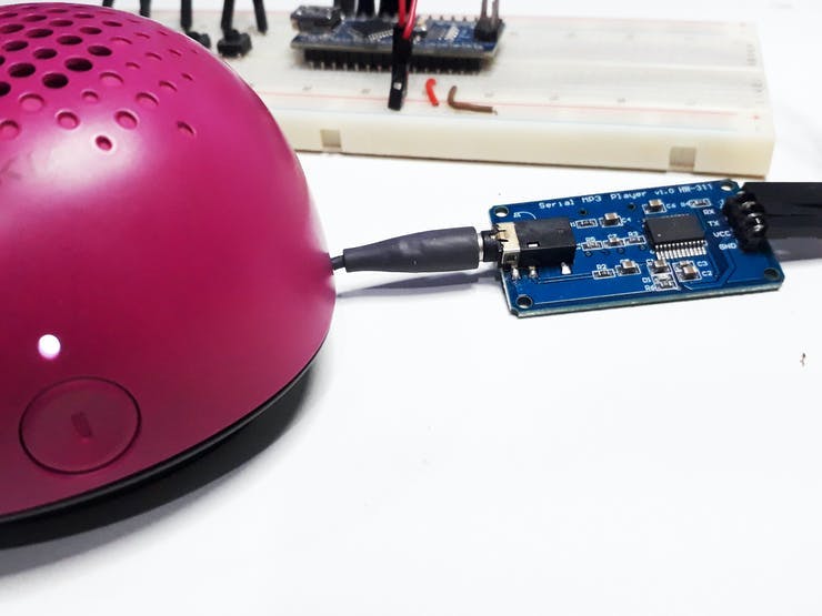
Through fun and entertaining activities, your students or your child can learn while playing. If you want to have fun with your students, get the board with vowels, and set up this project to have fun.
Conclusion
The main parts of the structure were verified and analyzed in order to better understand the importance of correct assembly, observing the function (according to the structure where it was fitted) of each component, as well as the functioning of the robot's neck rotation mechanism.
Therefore, from the development of the educational robot project, it was possible to analyze its mechanical structure and optimize the available spaces, both in the robot body and in the control.
The robot's structure was modeled with M3 sockets and screws for its fixation and thus, a better mechanical stability was created.
All its development was done with the aim of making it as didactic as possible for its later assembly with the electronic part.
Educational Robot for Children
*PCBWay community is a sharing platform. We are not responsible for any design issues and parameter issues (board thickness, surface finish, etc.) you choose.
- Comments(0)
- Likes(1)
-
 Engineer
Nov 30,2022
- 0 USER VOTES
- YOUR VOTE 0.00 0.00
- 1
- 2
- 3
- 4
- 5
- 6
- 7
- 8
- 9
- 10
- 1
- 2
- 3
- 4
- 5
- 6
- 7
- 8
- 9
- 10
- 1
- 2
- 3
- 4
- 5
- 6
- 7
- 8
- 9
- 10
- 1
- 2
- 3
- 4
- 5
- 6
- 7
- 8
- 9
- 10
 More by Silícios Lab silicioslab
-
 Electronic Enclosure applied for electronic projects
IntroductionWhen designing electronics, the enclosure plays a crucial role that is often overlooked....
-
 IoT Indoor system with ESP32 to monitor Temperature, Humidity, Pressure, and Air Quality
IntroductionAir quality, temperature, humidity and pressure are essential elements to ensure healthy...
-
 WS2812B RGB LED Controller with ESP8266 via WiFi
IntroductionWS2812b addressable RGB LEDs are devices widely used in lighting projects. They are foun...
-
 Electronic Board for Cutting Electrical Power to Devices and Machines
IntroductionAn energy saving system for cutting electrical energy in machines is a fundamental piece...
-
 PCB Board Home Automation with ESP8266
IntroductionThe incorporation of the ESP8266 module into home automation represents a significant ad...
-
 Dedicated Control Board for Mobile Robots with Wheels
IntroductionFor a long time we developed several prototypes and teaching kits of mobile robots and w...
-
 Traffic turn signal for bicycles
IntroductionDoes every project with electronic logic need a Microcontroller or Arduino to be develop...
-
 Mini Arduino with ATTINY85
Do you know the ATTINY85 microcontroller? This article has news and a gift for you. Many people deve...
-
 Christmas Tree
The tree used to signal light of Christmas.
-
 Electronic Enclosure applied for electronic devices
IntroductionWhen designing electronics, the enclosure plays a crucial role that is often overlooked....
-
 Electronic Enclosure for Programmable Logic Controller
The housing developed for programmable logic controllers is a practical and efficient solution for t...
-
 Payment PCB for machines and services
IntroductionIn many commercial establishments, hospitals and other places, there are video game equi...
-
 Relay High Power Printed Circuit Board
IntroductionEfficient management of electrical loads is essential for optimizing performance and saf...
-
 Weather gadget with clock through ESP8266
IntroductionImagine a device that combines technology with an elegant design, bringing functionality...
-
 ESP32 MPU6050 Monitor
IntroductionVarious industrial equipment is essential for the adequate production of products, parts...
-
 Digital Speedometer for Bicycles
IntroductionCycling, increasingly popular both as a recreational activity and as a means of transpor...
-
 Arduino-based development board with extra features
IntroductionArduino is an excellent tool for anyone who wants to develop prototypes. The board has a...
-
 How to develop low-energy devices powered by batteries?
IntroductionIn recent years, there has been a major advance in the area of embedded systems through ...
-
-
-
-
-
-
3D printed Enclosure Backplate for Riden RD60xx power supplies
154 1 1 -
-


