Traffic turn signal for bicycles
Introduction
Does every project with electronic logic need a Microcontroller or Arduino to be developed? Today, many people use Microcontrollers to solve a problem.
Is there an error in this? None! But the project may have increased costs and make it difficult to sell to end consumers. It is for this reason that we need to look for simple and viable solutions.
In the project presented in this article we will present this to you. In it we will show you how to implement a simple solution and investing little money with electronic components.
In this PCBWay article you will learn how to develop a sign to signal the change of direction of cyclists in traffic.
All files are allowed in this link. If you are smart, you can use it to create some PCBs and sell it for people or stores interested in ciclism.
Every year, several cyclists are involved in traffic accidents due to other people's mistakes or because they do not use adequate signage. This ends up causing many deaths and leaving people unable to get around.
To avoid this problem, PCBWay supported the development of a lane change signal for cyclists. In addition to providing security, the project is open and you can use it to sell to other cyclists.
It uses few electronic components and is easy to assemble. Now, let's understand the complete structure of the electronic circuit.
Electronic Circuit of the Turn Signal for Cyclists
The figure below shows the electronic circuit of the project.
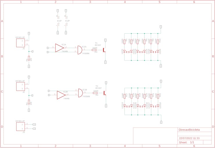
How does the electronic circuit work?
The electronic circuit is formed by a group of LEDs that will be used to signal that a cyclist will turn left or right. This will be done through the use of two buttons.
Each button will be connected to the handlebars of the bicycle and will be connected to the circuit on the board through wires.
The signal from each button is sent to the logic circuit input of the electronic board.
This circuit was developed using combinational logic. Through logic gates it was possible to implement the complete solution for this circuit.
What logic was implemented?
The combinational circuit is formed by two inputs, which are the left button and the right button.
Combinational logic works as follows:
- Turn off all LEDs when buttons are not pressed,
- Turn on the left LEDs when the left button is pressed,
- Turn on the right LEDs when the right button is pressed, and
- Turn off all LEDs when both buttons are pressed.
From this logic, a combinational table was created to relate the digital inputs with their respective digital outputs. See the table below.

This table presents the combinations of inputs and their respective digital outputs. From this table, a Boolean logic expression was developed and we set up the logic circuit below.
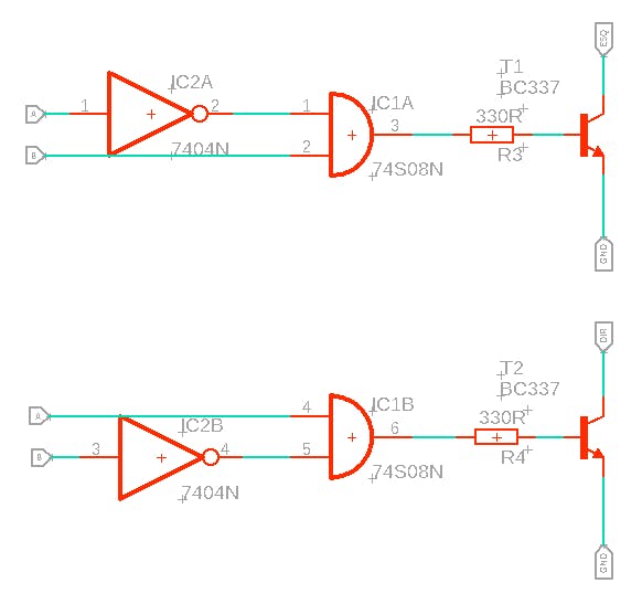
At the output of each circuit, transistors were placed to switch the set of 6 LEDs to signal left and right.
The group of LEDs is shown in the figure below.
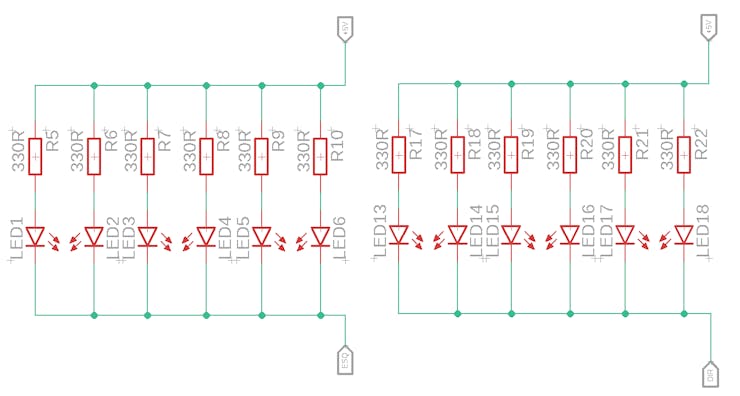
Each group of LEDs was connected to the collector terminal of each transistor. This allowed to drive all the LEDs through a single transistor.
Finally, we insert 3 screw connectors into the electronic circuit.
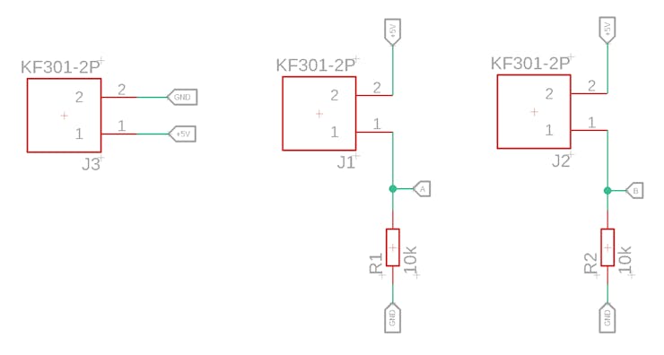
We have a connector for powering the electronic project with a +5V battery. The other 2 connectors will be used to connect the buttons. A 10kR pull-down resistor was inserted for each button.
Finally, we finalized the electronic schematic design and developed the layout of the printed circuit board. See the result in the figure below.
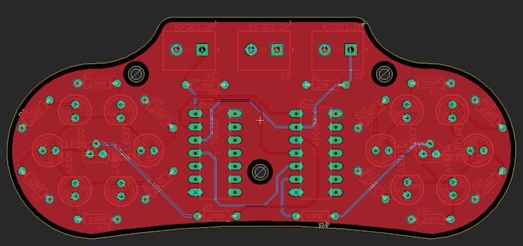
3 holes were inserted in the electronic board to facilitate the fixing of the board on the bicycle frame or in another place desired by the cyclist.
The following is the full 3D view of the board in Fusion 360 software.
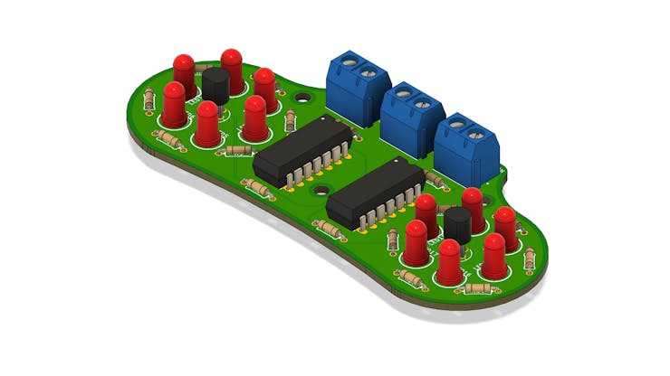
This electronic board is easy to assemble and you can find the components in any store in your city, as THT electronic components were used and this facilitates the board assembling process for any user who wants to use it.
Develop with Microcontroller or Logic Circuit?
As you can see, we implemented the entire electronic circuit with combinational logic and used only 2 digital integrated circuits to solve this problem.
The same circuit could be developed and programmed by a Microcontroller, but, as mentioned before, the costs are high and the profit margin in case of sales is reduced.
That's why we carried out a preliminary analysis of the problem and built it in a simple, cheap and viable way to be assembled by anyone.
For less than $2 you can assemble an electronic board and sell it to people interested in protecting themselves during cycling activities while in transit.
Take advantage now and order 10 electronic boards on PCBWay for $5.

Traffic turn signal for bicycles
*PCBWay community is a sharing platform. We are not responsible for any design issues and parameter issues (board thickness, surface finish, etc.) you choose.

Raspberry Pi 5 7 Inch Touch Screen IPS 1024x600 HD LCD HDMI-compatible Display for RPI 4B 3B+ OPI 5 AIDA64 PC Secondary Screen(Without Speaker)
BUY NOW
ESP32-S3 4.3inch Capacitive Touch Display Development Board, 800×480, 5-point Touch, 32-bit LX7 Dual-core Processor
BUY NOW
Raspberry Pi 5 7 Inch Touch Screen IPS 1024x600 HD LCD HDMI-compatible Display for RPI 4B 3B+ OPI 5 AIDA64 PC Secondary Screen(Without Speaker)
BUY NOW- Comments(0)
- Likes(4)
 Log in to post comments.
- 0 USER VOTES
- YOUR VOTE 0.00 0.00
- 1
- 2
- 3
- 4
- 5
- 6
- 7
- 8
- 9
- 10
- 1
- 2
- 3
- 4
- 5
- 6
- 7
- 8
- 9
- 10
- 1
- 2
- 3
- 4
- 5
- 6
- 7
- 8
- 9
- 10
- 1
- 2
- 3
- 4
- 5
- 6
- 7
- 8
- 9
- 10
 More by Silícios Lab silicioslab
-
 Electronic Enclosure for Programmable Logic Controller
The housing developed for programmable logic controllers is a practical and efficient solution for t...
-
 Payment PCB for machines and services
IntroductionIn many commercial establishments, hospitals and other places, there are video game equi...
-
 Relay High Power Printed Circuit Board
IntroductionEfficient management of electrical loads is essential for optimizing performance and saf...
-
 Weather gadget with clock through ESP8266
IntroductionImagine a device that combines technology with an elegant design, bringing functionality...
-
 ESP32 MPU6050 Monitor
IntroductionVarious industrial equipment is essential for the adequate production of products, parts...
-
 Digital Speedometer for Bicycles
IntroductionCycling, increasingly popular both as a recreational activity and as a means of transpor...
-
 How to measure weight with Load Cell and HX711
IntroductionThe purpose of this project is to develop a printed circuit board (PCB) that allows weig...
-
 Electronic Enclosure applied for electronic projects
IntroductionWhen designing electronics, the enclosure plays a crucial role that is often overlooked....
-
 IoT Indoor system with ESP32 to monitor Temperature, Humidity, Pressure, and Air Quality
IntroductionAir quality, temperature, humidity and pressure are essential elements to ensure healthy...
-
 WS2812B RGB LED Controller with ESP8266 via WiFi
IntroductionWS2812b addressable RGB LEDs are devices widely used in lighting projects. They are foun...
-
 Electronic Board for Cutting Electrical Power to Devices and Machines
IntroductionAn energy saving system for cutting electrical energy in machines is a fundamental piece...
-
 PCB Board Home Automation with ESP8266
IntroductionThe incorporation of the ESP8266 module into home automation represents a significant ad...
-
 Dedicated Control Board for Mobile Robots with Wheels
IntroductionFor a long time we developed several prototypes and teaching kits of mobile robots and w...
-
 Traffic turn signal for bicycles
IntroductionDoes every project with electronic logic need a Microcontroller or Arduino to be develop...
-
 Mini Arduino with ATTINY85
Do you know the ATTINY85 microcontroller? This article has news and a gift for you. Many people deve...
-
 Christmas Tree
The tree used to signal light of Christmas.
-
 IoT Access control and communication system with Raspberry Pi/PC using ESP32
IntroductionIn the world of automation and the Internet of Things (IoT), access control systems have...
-
 Electronic Enclosure applied for electronic devices
IntroductionWhen designing electronics, the enclosure plays a crucial role that is often overlooked....
-
 Electronic Enclosure for Programmable Logic Controller
The housing developed for programmable logic controllers is a practical and efficient solution for t...
-
 Payment PCB for machines and services
IntroductionIn many commercial establishments, hospitals and other places, there are video game equi...
-
 Relay High Power Printed Circuit Board
IntroductionEfficient management of electrical loads is essential for optimizing performance and saf...
-
 Weather gadget with clock through ESP8266
IntroductionImagine a device that combines technology with an elegant design, bringing functionality...
-
 ESP32 MPU6050 Monitor
IntroductionVarious industrial equipment is essential for the adequate production of products, parts...
-
 Digital Speedometer for Bicycles
IntroductionCycling, increasingly popular both as a recreational activity and as a means of transpor...
-
 How to measure weight with Load Cell and HX711
IntroductionThe purpose of this project is to develop a printed circuit board (PCB) that allows weig...
-
 Electronic Enclosure applied for electronic projects
IntroductionWhen designing electronics, the enclosure plays a crucial role that is often overlooked....
-
 IoT Indoor system with ESP32 to monitor Temperature, Humidity, Pressure, and Air Quality
IntroductionAir quality, temperature, humidity and pressure are essential elements to ensure healthy...
-
 WS2812B RGB LED Controller with ESP8266 via WiFi
IntroductionWS2812b addressable RGB LEDs are devices widely used in lighting projects. They are foun...
-
 Electronic Board for Cutting Electrical Power to Devices and Machines
IntroductionAn energy saving system for cutting electrical energy in machines is a fundamental piece...
-
 PCB Board Home Automation with ESP8266
IntroductionThe incorporation of the ESP8266 module into home automation represents a significant ad...
-
-
Commodore 64 1541-II 1581 Floppy Disk Drive C64 Power Supply Unit USB-C 5V 12V DIN connector 5.25
394 1 3 -
-
-
-
-
-
-
-
Modifying a Hotplate to a Reflow Solder Station
1256 1 6 -
MPL3115A2 Barometric Pressure, Altitude, and Temperature Sensor
715 0 1 -


