|
C503B-RBS-CW0Z0AA2Cree LED
|
x 1 | |

|
NE555PSRTexas Instruments
|
x 1 | |

|
CD40174BETexas Instruments
|
x 1 | |

|
Resistor 220 0603YAGEO
|
x 1 | |
|
|
100k trimmer |
x 1 |
NE555 Led Chaser
What is the LED Chaser Circuit?
A light chaser serves as an LED driving circuit. It contains an arrangement of LEDs set in a certain pattern to provide a chasing light effect. For example, the LED chaser circuit creates the flashing light effect in a disco. Additionally, these popular circuits have common applications in signals, running-light rope, or advertising displays, producing pulsing light patterns.
More complex circuits usually contain microcontroller IC’s. In comparison, a simpler version requires the integration of ordinary IC’s, including the 555 and 4017. Many circuits utilize a CD4017 Johnson 10 stage decade counter. In effect, the electronic unit triggers the LEDs to switch on/off in a predetermined and repetitive cycle. As a result, this produces a visually appealing display with different light patterns around the LEDs.
A chase is an electrical application where strings of adjacent light bulbs cycle on and off frequently to give the illusion of lights moving along the string. With computerized lighting consoles, building chase sequences has become easier, while previously chases used mechanical means, such as a wheel with an electrified spindle which strikes electrical contacts for each circuit.
Chase lights (or chaser lights) are often associated with the marquee signs of some movie theaters, and have also been used as a common element of television game show sets.
Creating a chase effect
In order to achieve a chase "strip lights" are most often used, especially when used in "theatrical" applications.
Similar design is used in computing, where it is known as "marching ants"
Several separate circuits of lights (called channels) are needed to create a chase effect which is a simulation of motion achieved by turning these circuits ON and OFF in sequence. The standard is 3 or 4 channels. For 4 channels the lights are wired with one common and 4 different feeds. Light #1 is wired with lights #5 & 9 & 13, etc. (+4); Light #2 is wired with lights #6 & 10 & 14, etc. (+4); Light #3 is wired with lights #7 & 11 & 15, etc. (+4); Light #4 is wired with lights #8 & 12 & 16, etc. (+4).

Marquees with 12 lights grouped into 2, 3 and 4 channels (click for SMIL animation)

Floodlights with a chase effect, traditionally known as cyclorama lights
The most common 4 channel chase which is seen in a theater Marquee perimeter lighting and other lighting animation applications consists of 4 channel wired light bulbs and an electronic chaser. The electronic chaser turns channel #1 ON while all the other Channels remain OFF. Then after an adjustable period of time it turns OFF channel #1 while turning ON channel #2, then turn OFF channel #2 while turning ON channel #3, then turn OFF channel #3 while turning ON channel #4, then repeat. This creates the illusion that the lights are moving in one direction. Some digital lighting chasers are made to do the above described single light chase pattern along with other combinations of Turning ON and OFF of the light to create different sequences like forward light chase, backward light chase, bouncing, dark chase (1 channel OFF while all 3 others ON), etc... Also, more than 4 channel chasers are used to create more effects and to animate illuminated objects.
Chase circuits using LEDs are commonly built by electronics hobbyists with timer (such as the 555 timer IC) and counter (such as the 4017, which allows up to 10 channels) integrated circuits.
Light-emitting diode
A light-emitting diode (LED) is a semiconductor light source that emits light when current flows through it. Electrons in the semiconductor recombine with electron holes, releasing energy in the form of photons. The color of the light (corresponding to the energy of the photons) is determined by the energy required for electrons to cross the band gap of the semiconductor. White light is obtained by using multiple semiconductors or a layer of light-emitting phosphor on the semiconductor device.
Appearing as practical electronic components in 1962, the earliest LEDs emitted low-intensity infrared (IR) light. Infrared LEDs are used in remote-control circuits, such as those used with a wide variety of consumer electronics. The first visible-light LEDs were of low intensity and limited to red. Early LEDs were often used as indicator lamps, replacing small incandescent bulbs, and in seven-segment displays. Recent developments have produced LEDs available in visible, ultraviolet (UV), and infrared wavelengths, with high, low, or intermediate light output, for instance white LEDs suitable for room and outdoor area lighting. LEDs have also given rise to new types of displays and sensors, while their high switching rates are useful in advanced communications technology with applications as diverse as aviation lighting, fairy lights, automotive headlamps, advertising, general lighting, traffic signals, camera flashes, lighted wallpaper, horticultural grow lights, and medical devices.
LEDs have many advantages over incandescent light sources, including lower power consumption, longer lifetime, improved physical robustness, smaller size, and faster switching. In exchange for these generally favorable attributes, disadvantages of LEDs include electrical limitations to low voltage and generally to DC (not AC) power, inability to provide steady illumination from a pulsing DC or an AC electrical supply source, and lesser maximum operating temperature and storage temperature. In contrast to LEDs, incandescent lamps can be made to intrinsically run at virtually any supply voltage, can utilize either AC or DC current interchangeably, and will provide steady illumination when powered by AC or pulsing DC even at a frequency as low as 50 Hz. LEDs usually need electronic support components to function, while an incandescent bulb can and usually does operate directly from an unregulated DC or AC power source.
The first commercial visible-wavelength LEDs were commonly used as replacements for incandescent and neon indicator lamps, and in seven-segment displays,[30] first in expensive equipment such as laboratory and electronics test equipment, then later in such appliances as calculators, TVs, radios, telephones, as well as watches (see list of signal uses). Until 1968, visible and infrared LEDs were extremely costly, in the order of US$200 per unit, and so had little practical use.
555 timer IC
The 555 timer IC is an integrated circuit (chip) used in a variety of timer, delay, pulse generation, and oscillator applications. Derivatives provide two (556) or four (558) timing circuits in one package. The design was first marketed in 1972 by Signetics. Since then, numerous companies have made the original bipolar timers, as well as similar low-power CMOS timers. In 2017, it was said that over a billion 555 timers are produced annually by some estimates, and that the design was "probably the most popular integrated circuit ever made"
Features
Timing From Microseconds to Hours
Astable or Monostable Operation
Adjustable Duty Cycle
TTL-Compatible Output Can Sink or Source
Up to 200 mA
On Products Compliant to MIL-PRF-38535,
All Parameters Are Tested Unless Otherwise Noted. On All Other Products, Production Processing Does Not Necessarily Include
Testing of All Parameters.
CD4017 Ic
The CD4017 is a CMOS Decade counter IC. CD4017 is used for low range counting applications. It can count from 0 to 10 (the decade count). The circuit designed by using this ic will save board space and also time required to design the circuit. CD4017 is as ‘Johnson 10 stage decade counter’.
Features
The supply voltage of this IC is 3V to 15V.
It is compatible with TTL (Transistor -Transistor Logic).
The clock speed or operational speed of CD4017 IC is 5 MHz.
This IC is also used in electronic industries, automotive industries, manufacturing medical electronic devices, alarms and in electronic instrumentation devices.
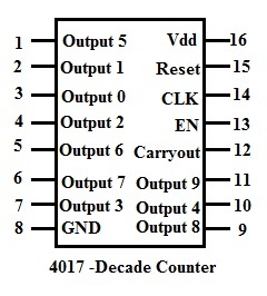
CD4017 Pin description
It has 16 I/O pins.
Output pins of CD4017(Pin 1 to 7 & 9 to 11)
Pins 1 to 7 and 9 to 11 are outputs pins.
These pins changes to ‘high’ level one by one (one after another) in a sequence. For each clock signal each pin goes high in a sequence.
Enable pin/Clock Inhibit(Pin 13)
Enable pin enables the CD4017 IC.IC is enabled when the pin is active low.
In order to disable or switch off the IC,this pin should be connected to active high input.When this pin is active high ,it ignores the clock signals.
Clock pin(pin 14)
Clock signal provided to 14 th is responsible for sequential output.
When the first clock pulse is detected pin 3 goes ,for next clock pulse pin2 goes high,like this sequence is formed.
The important thing to remember is, if we don’t connect any clock signal to this input pin, it must be connected to either positive or negative voltage supply.
It is not left unconnected as per the CMOS input standard rules.
The clock input pin (pin number 14) responds only to the positive voltage signal or positive clock
Reset pin(Pin 15)
Reset pin resets the output of the sequence.That is the current state of the output sequence is set to initial state.
Reset pin should be connected to ground in order to reset the circuit.
Ground pin & supply pin(Pin 8 & Pin 16)
Pin number 8 acts as ground and it must be connected to negative supply voltage & pin number 16 is the supply pin for CD4017 and it is connected to positive voltage supply.
Carry out pin(pin12)
The pin 12 is supplied with the CARRY OUT signal. It completes one full cycle for every 10 clock cycles. This is used to ‘ripple’ the IC, which means to delay in counting operations.
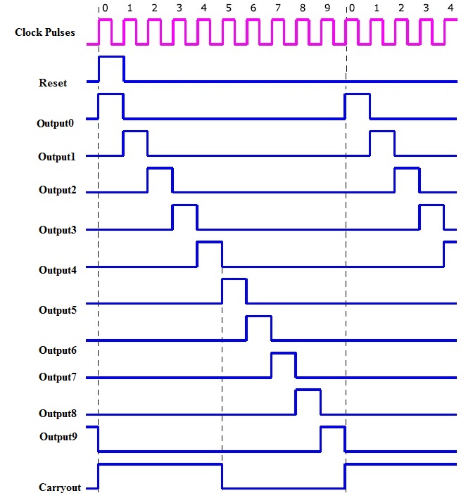
Counting operation of CD4017 using waveforms

This is the timing diagram of the CD4017 with, shows us the comparison and also explains the counting sequence of the outputs, shifting from one pin to its next.
If we observe that, before applying the clock signal, the RESET is set to High, so the reset pin input sets all the output to their initial state.
Then the output of the first output pin 3 will be high. Next this output is shifted to its next output pin and this sequence continues till the next clock cycle.
Let us see some examples in which CD4017 is used.
Application of CD4017
LED Sequencer using 4017
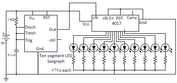
The LED sequencer circuit by using CD4017 and IC 555 is shown below. This circuit is also called as “LED chaser circuit”.
Components
CD4017 decade counter
555 timer IC
Ten-segment bar graph LED
switch and One 6 volt battery
1 MΩ resistor
0.1 μF capacitor
Coupling capacitor, 0.047 to 0.001 μF
470 Ω resistors-10
Primarily it is important to remember that, as the CD4017 is a CMOS device, it is very sensitive to the static electricity.


NE555 Led Chaser
*PCBWay community is a sharing platform. We are not responsible for any design issues and parameter issues (board thickness, surface finish, etc.) you choose.
- Comments(0)
- Likes(0)
- 0 USER VOTES
- YOUR VOTE 0.00 0.00
- 1
- 2
- 3
- 4
- 5
- 6
- 7
- 8
- 9
- 10
- 1
- 2
- 3
- 4
- 5
- 6
- 7
- 8
- 9
- 10
- 1
- 2
- 3
- 4
- 5
- 6
- 7
- 8
- 9
- 10
- 1
- 2
- 3
- 4
- 5
- 6
- 7
- 8
- 9
- 10
 More by Sreeram.zeno
-
 Esp12-F Cluster V1.0
The ESP8266 is a low-cost Wi-Fi microchip, with built-in TCP/IP networking software, and microcontro...
-
 TB6612FNG Motor Driver
The TB6612FNG Motor Driver can control up to two DC motors at a constant current of 1.2A (3.2A peak)...
-
 Sunny Buddy Solar Charger v1.0
This is the Sunny Buddy, a maximum power point tracking (MPPT) solar charger for single-cell LiPo ba...
-
 Diy 74HC4051 8 Channel Mux Breakout Pcb
The 74HC4051; 74HCT4051 is a single-pole octal-throw analog switch (SP8T) suitable for use in analog...
-
 Diy RFM97CW Breakout Pcb
IntroductionLoRa? (standing for Long Range) is a LPWAN technology, characterized by a long range ass...
-
 ProMicro-RP2040 Pcb
The RP2040 is a 32-bit dual ARM Cortex-M0+ microcontroller integrated circuit by Raspberry Pi Founda...
-
 Serial Basic CH340G Pcb
A USB adapter is a type of protocol converter that is used for converting USB data signals to and fr...
-
 Mp3 Shield For Arduino
Hardware OverviewThe centerpiece of the MP3 Player Shield is a VS1053B Audio Codec IC. The VS1053B i...
-
 MRK CAN Shield Arduino
The CAN-BUS Shield provides your Arduino or Redboard with CAN-BUS capabilities and allows you to hac...
-
 AVR ISP Programmer
AVR is a family of microcontrollers developed since 1996 by Atmel, acquired by Microchip Technology ...
-
 Diy Arduino mega Pcb
The Arduino Mega 2560 is a microcontroller board based on the ATmega2560. It has 54 digital input/ou...
-
 Max3232 Breakout Board
MAX3232 IC is extensively used for serial communication in between Microcontroller and a computer fo...
-
 Line Follower Pcb
The Line Follower Array is a long board consisting of eight IR sensors that have been configured to ...
-
 HMC6343 Accelerometer Module
The HMC6343 is a solid-state compass module with tilt compensation from Honeywell. The HMC6343 has t...
-
 RTK2 GPS Module For Arduino
USBThe USB C connector makes it easy to connect the ZED-F9P to u-center for configuration and quick ...
-
 Arduino Explora Pcb
The Arduino Esplora is a microcontroller board derived from the Arduino Leonardo. The Esplora differ...
-
 Diy Stepper Motor Easy Driver
A motor controller is a device or group of devices that can coordinate in a predetermined manner the...
-
 Diy Arduino Pro Mini
The Arduino Pro Mini is a microcontroller board based on the ATmega168 . It has 14 digital input/out...
-
-
mammoth-3D SLM Voron Toolhead – Manual Drill & Tap Edition
214 0 0 -
-
AEL-2011 Power Supply Module
736 0 2 -
AEL-2011 50W Power Amplifier
610 0 2 -
-
-
Custom Mechanical Keyboard
814 0 0 -
Tester for Touch Screen Digitizer without using microcontroller
442 2 2 -
Audio reactive glow LED wristband/bracelet with NFC / RFID-Tags
395 0 1 -
-


