SmartController-3v
Mushroom House Controller – Part 1
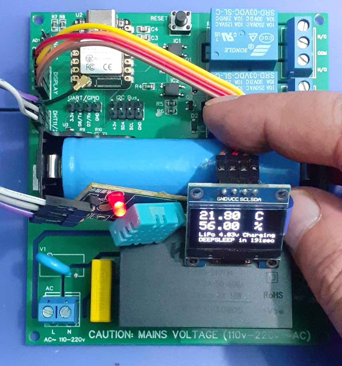
A Collaboration with Maesai Prasisart School, Maesai, Chiang Rai, Thailand
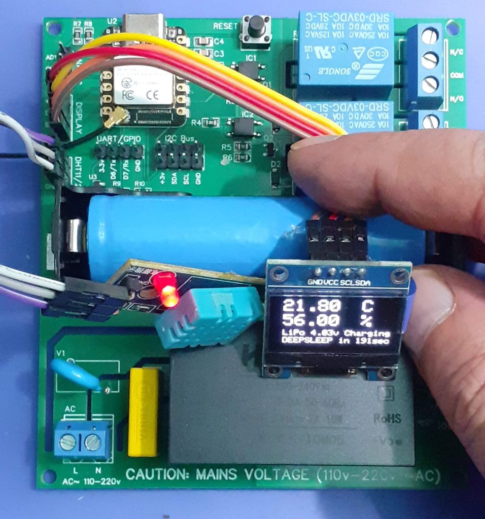
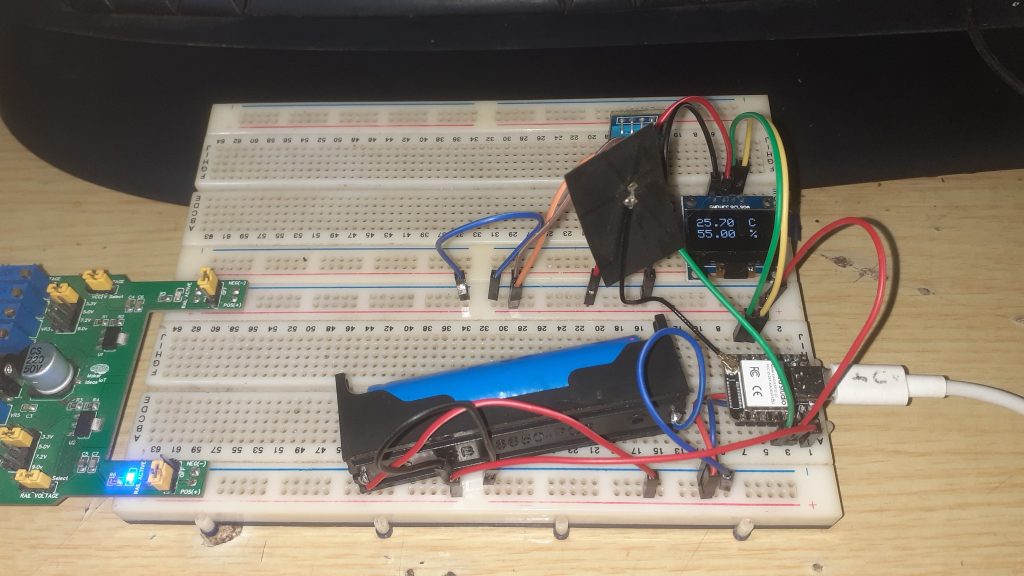
A short while ago, the local high school in my area and myself decided to collaborate on a real-world project regarding an IoT device. The device (prototype above) will be used as a controller in an Oyster Mushroom growing house, which in turn will be managed by the members of a local disabled persons association. This is very exciting for a few reasons…
I will get the opportunity to teach interested students how to solve real-world problems using electronics, as well we will do something for the community and thus contribute to making the lives of the local disabled people a bit easier.
In the long term, the data collected by the device can be used to teach other mushroom growers in the area about the optimum environment to help them ensure that they get the perfect harvest every time…
In this post, I will thus do things a little differently from my normal setup, and focus more on the collaboration, as well as teaching moments. I shall also include quite a lot of pictures. The usual schematics and PCB descriptions shall still be available, but only on the PCBWay Shared projects page ( link to be added in due course)
The initial idea is to produce two different PCB’s with basically the same function, for the time being designed by myself. One, used in this post, will be a 3.3v version, with battery backup, and the other will be a 5v version, with level converters ( I could not resist the potential teaching opportunity that these provided) and no battery backup. The 5v version, which I shall introduce in part 2 will be assembled by the students, while I shall assemble the 3.3v version.
Further to that, the goal is to break the PCB up into logical modules and teach the students about each module. Their task would be to then design a PCB of that module, and in the end, combine all the modules into a functional project.
As a further part to this, a special interest group shall then make use of the knowledge learnt during the development of the modules to design a third PCB including all of those modules, as well as any other that they find may be needed, assemble it and use it in the real world.
Gallery – At the remote site
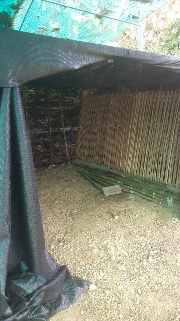
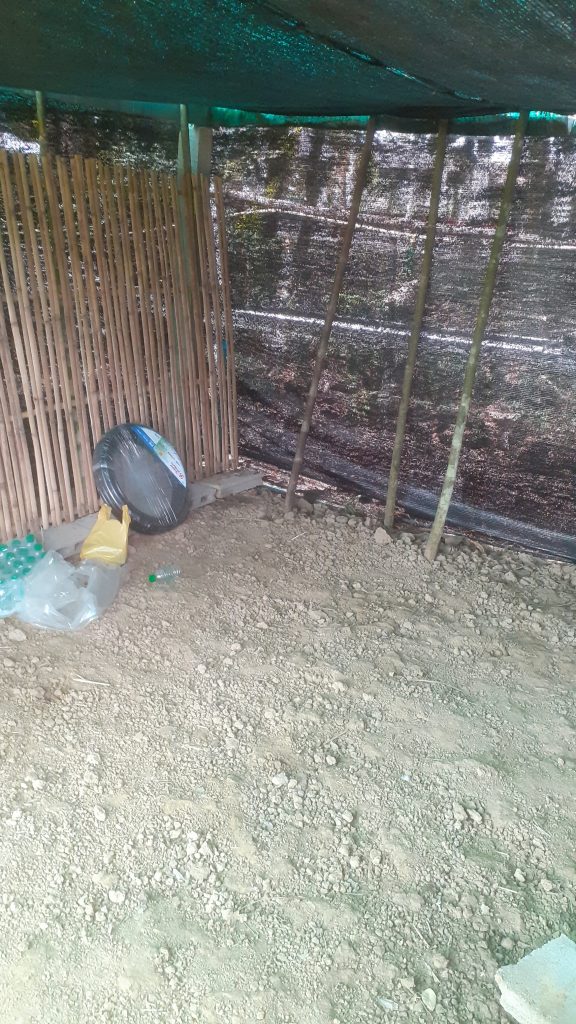
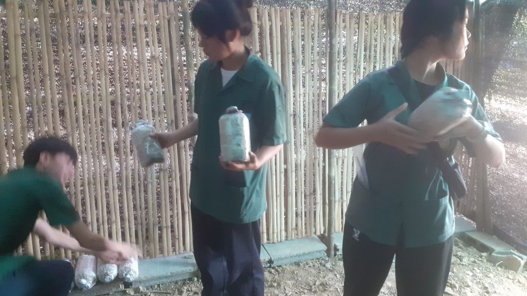
Over here, Grade 12 students assist in the construction of a mushroom house.
The pictures do not need a lot of captions, as they are quite self-explanatory
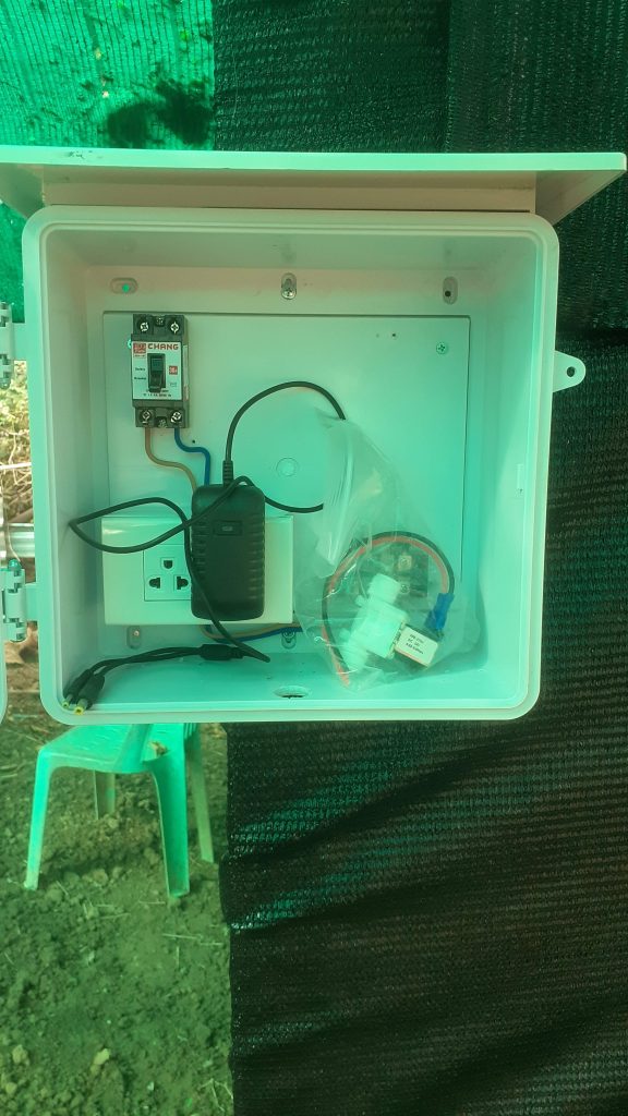
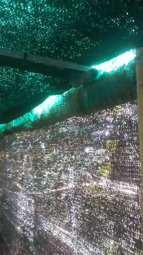
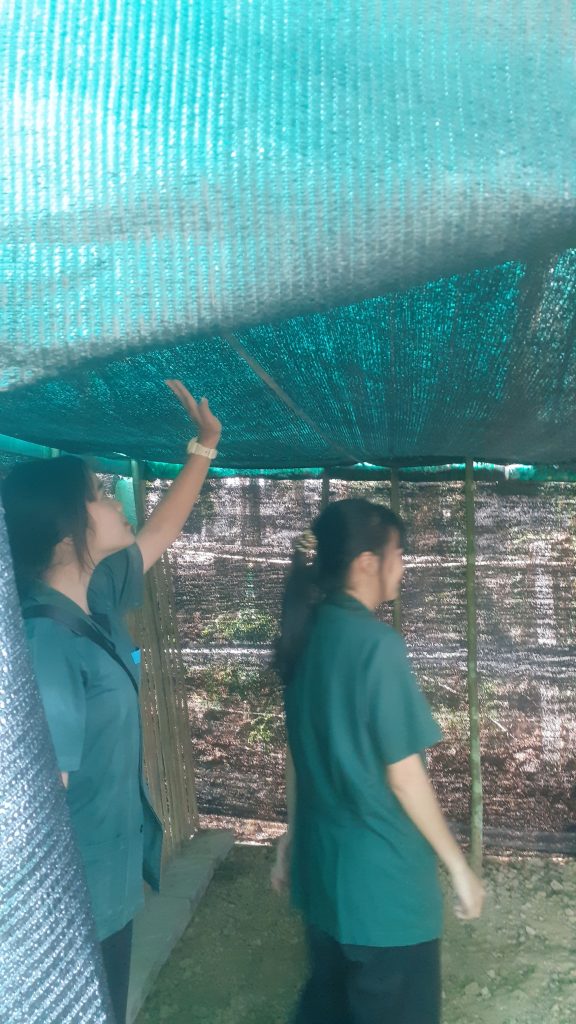
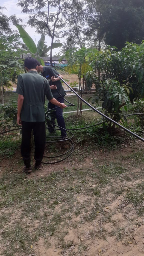
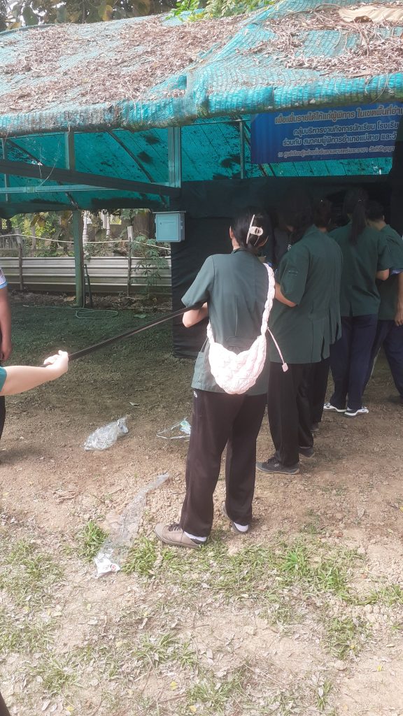
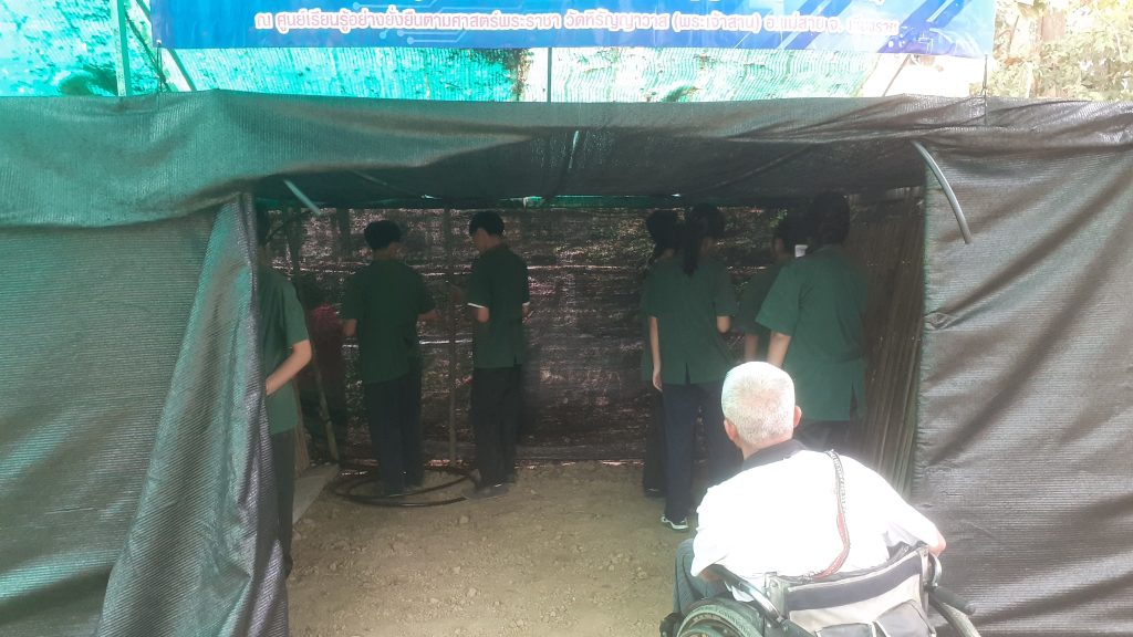
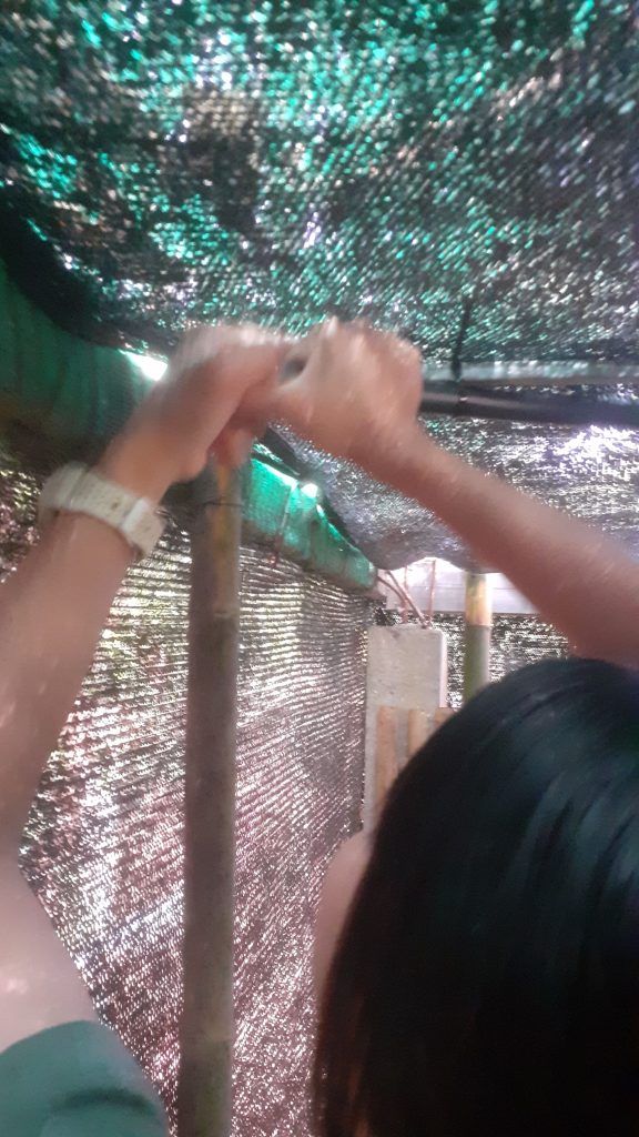
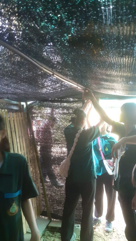
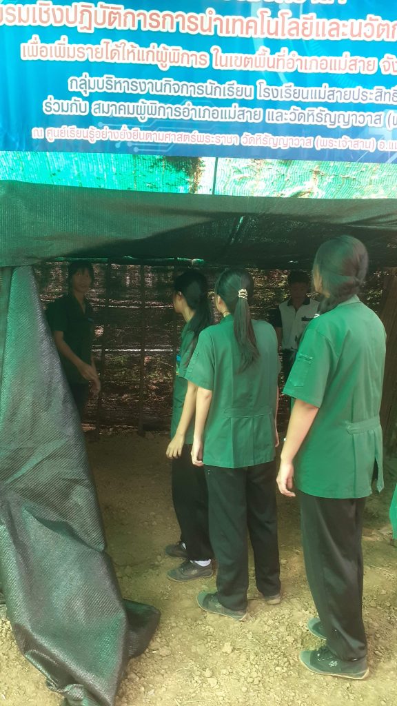
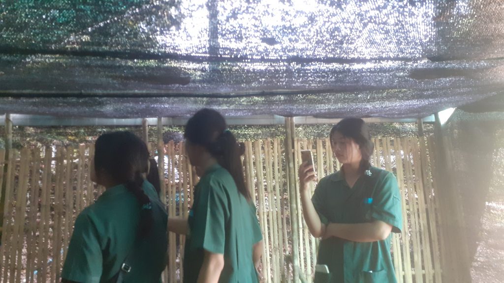
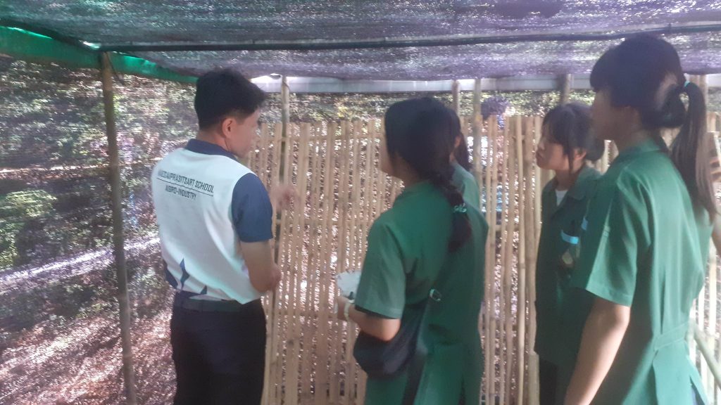


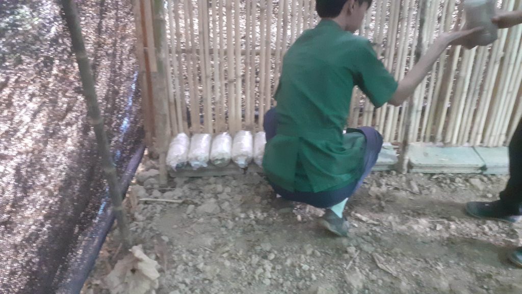
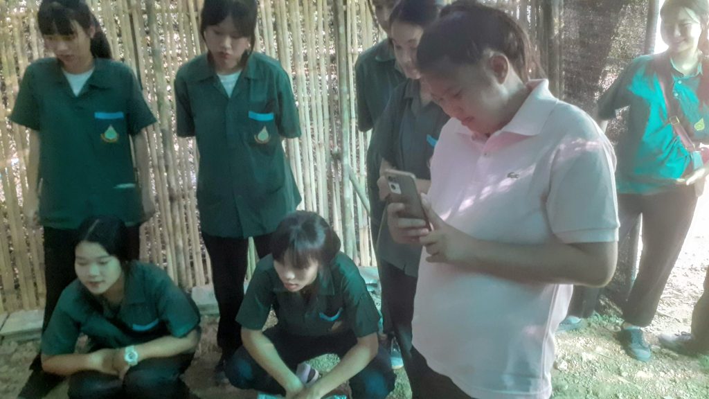

The next day, in the classroom
We started with a prototype on a breadboard, with some basic firmware. This was followed by a simple PCB design (with frequent 3D views so that the students could see what was happening)
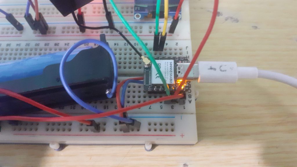
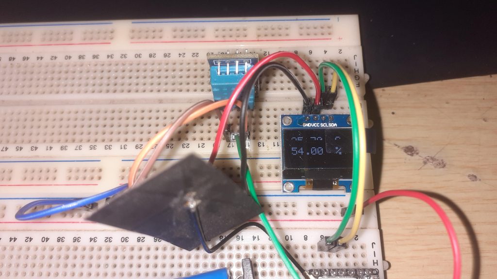
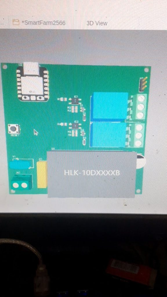
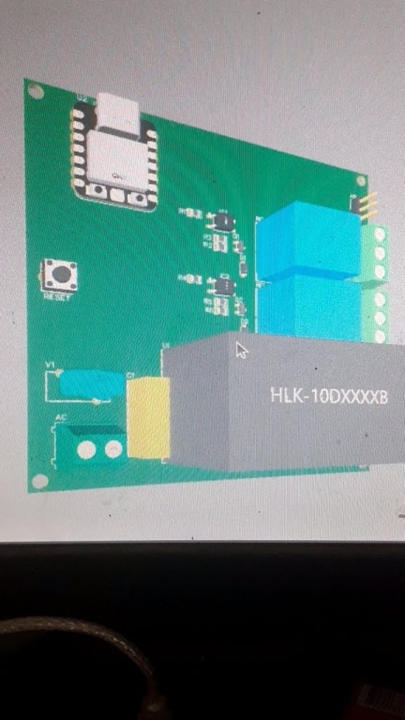
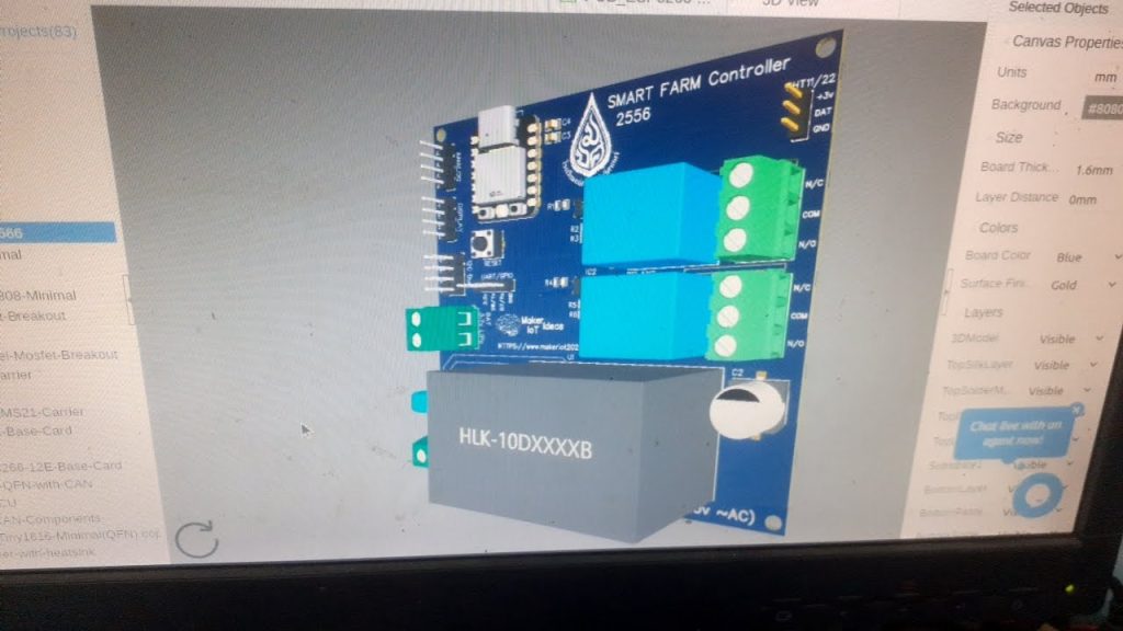
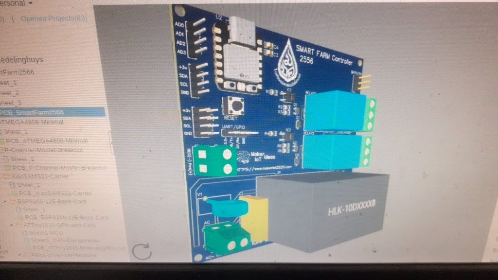
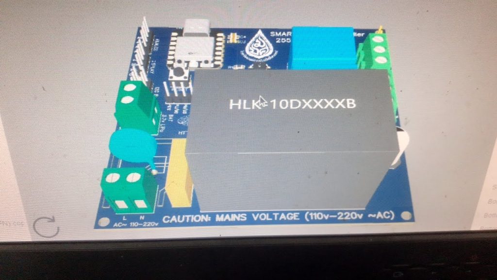
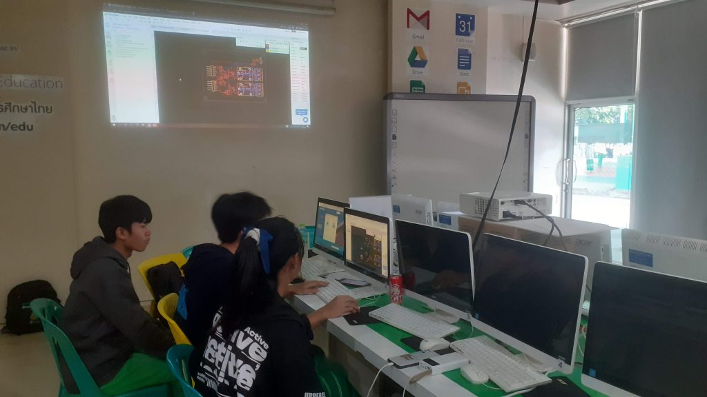
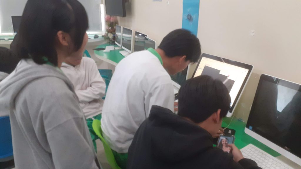
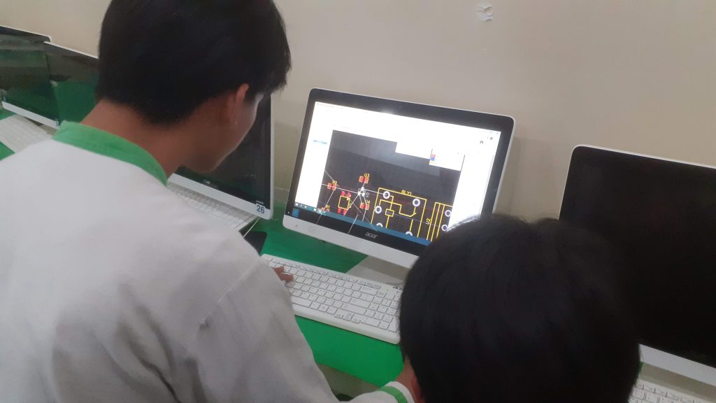
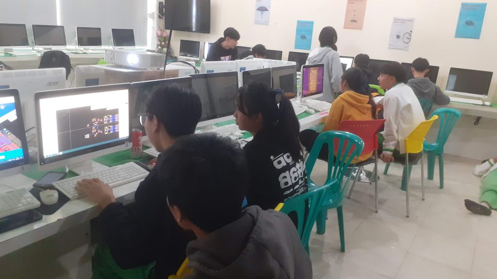
This was followed by a practical session where the students had the opportunity to try their hand at designing a part of the PCB. It is quite important that we understand that this is the very very first time in their lives that they were ever exposed to this. They were all extremely excited and some grasped the concepts quite fast, while others took a more cautious approach…
Manufacturing the PCB
Now it was up to me to finalise the initial design and get it manufactured.
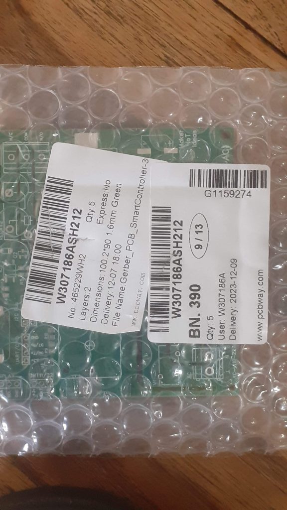
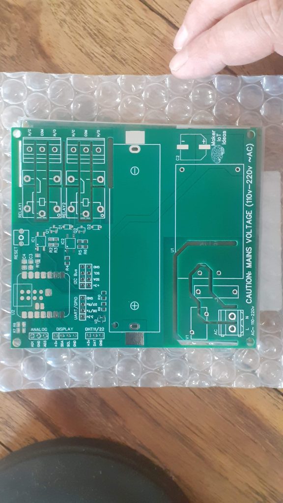
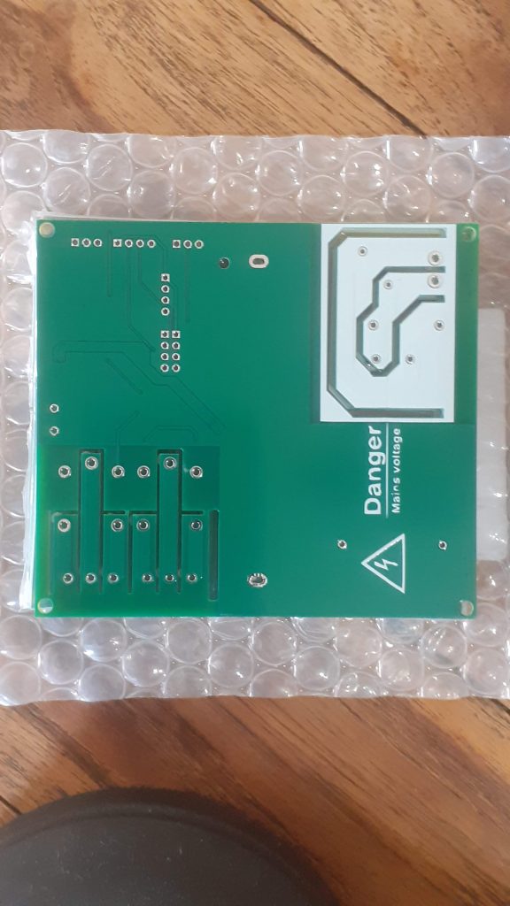
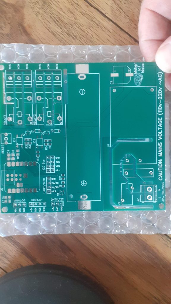
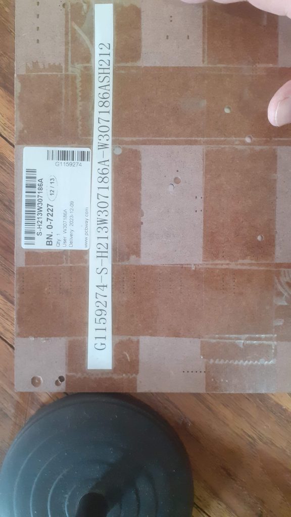
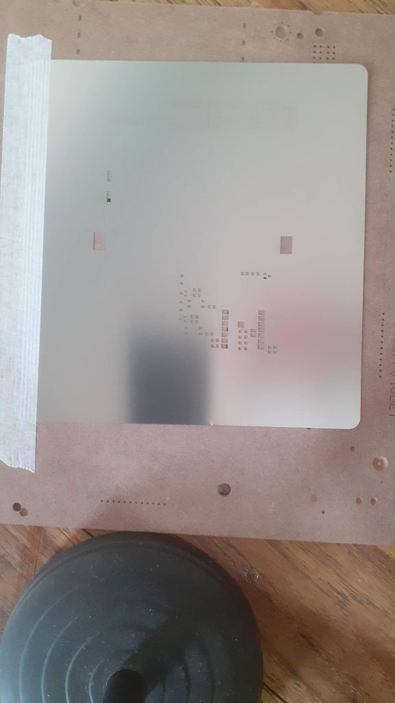
I choose PCBWay for my PCB manufacturing. Why? What makes them different from the rest?
PCBWay‘s business goal is to be the most professional PCB manufacturer for prototyping and low-volume production work in the world. With more than a decade in the business, they are committed to meeting the needs of their customers from different industries in terms of quality, delivery, cost-effectiveness and any other demanding requests. As one of the most experienced PCB manufacturers and SMT Assemblers in China, they pride themselves to be our (the Makers) best business partners, as well as good friends in every aspect of our PCB manufacturing needs. They strive to make our R&D work easy and hassle-free.
How do they do that?
PCBWay is NOT a broker. That means that they do all manufacturing and assembly themselves, cutting out all the middlemen, and saving us money.
PCBWay’s online quoting system gives a very detailed and accurate picture of all costs upfront, including components and assembly costs. This saves a lot of time and hassle.
PCBWay gives you one-on-one customer support, that answers you in 5 minutes ( from the Website chat ), or by email within a few hours ( from your personal account manager). Issues are really resolved very quickly, not that there are many anyway, but, as we are all human, it is nice to know that when a gremlin rears its head, you have someone to talk to who will do his/her best to resolve your issue as soon as possible.
Find out more here


Conclusion – Part 1
The assembly of the first board was done by myself, and firmware development was started. Stay tuned for Part 2 where the students will get the opportunity to assemble a SMD PCB for the very first time in their lives
#include <SPI.h>
#include <Wire.h>
#include <Adafruit_GFX.h>
#include <Adafruit_SSD1306.h>
#include <Adafruit_Sensor.h>
#include <DHT.h>
#include <DHT_U.h>


/*
 * Conditional Defines
 *
 * These are switches to allow for different versions of the Smart Farm Controller
 * to be used with the same firware, as well as to enable/disable serial debugging
 * NOTE that deep sleep does NOT FUNCTION CORRECTLY when serial debugging is active.
 * THIS IS AN ISSUE WITH THE ESP32S3 AND NOT THE FIRMWARE.
 *
 *
*/

//#define DEBUG-SERIAL
// Enable below for the 3.3v version of the hardware, IF it has a lipo battery installed
//#define HAS_LIPO
// Enable only is NO lipo battery installed, DONT USE together with HAS_LIPO
#define MAINS_PWR
// ENABLE if the DHT11 Sensor's power is controlled with a transistor.
// This is standard on the 3.3v version, where power saving is important.
#define DHT_SW
// THIS IS THE TIME THAT THE "FOG" relay will allow water to be released
#define FOG_DELAY 10000
// TOP Value of the Humidity Window
#define FOG_HIGH 80
// BOTTOM  Value of the Humidity Window
#define FOG_LOW 70
// HOW LONG to Sleep During DEEP SLEEP MODE - 10 Minutes is Maximum, Value is in seconds
#define TIME_TO_SLEEP  600
// HOW LONG TO STAY AWAKE (RUN) - Value is in seconds
#define TIME_AWAKE 300

/*
 * PLEASE NOTE THAT THE DEVICE SHALL NOT ENTER DEEP SLEEP IN THE EVENT THAT HUMIDITY LEVELS
 * HAVE DROPPED OUTSIDE OF THE ALLOWED WINDOW.
 * NORMAL DEEP SLEEP SHALL RESUME WHEN THE HUMIDITY VALUE IS BACK IN THE CORRECT WINDOW
 */

/*
 * ===================================================================================================
 * ============ DO NOT EDIT BELOW THIS BLOCK - UNLESS YOU KNOW WHAT YOU ARE DOING ====================
 * ===================================================================================================
 */


// Variables and Constants
#define DHTPIN 9
#define DHTTYPE    DHT11     // DHT 11
#define Relay1 8
#define Relay2 7
#define SCREEN_WIDTH 128 // OLED display width, in pixels
#define SCREEN_HEIGHT 64 // OLED display height, in pixels
#define OLED_RESET     -1 // Reset pin # (or -1 if sharing Arduino reset pin)
#define SCREEN_ADDRESS 0x3C ///< See datasheet for Address; 0x3D for 128x64, 0x3C for 128x32
#ifdef DHT_SW
#define DHT_Pin 3 // THIS IS NOT THE DATA PIN, IT IS A CONTROL TRANSISTOR, PRESENT ONLY ON THE 3.3v Version of the controller
#endif
#define uS_TO_S_FACTOR 1000000ULL  /* Conversion factor for micro seconds to seconds */
const int ledPin = LED_BUILTIN;
int ledState = LOW;
unsigned long previousMillis = 0;
unsigned long previousFog = 0;
uint32_t delayMS;
float temperature = 0;
float humidity = 0;
#ifdef HAS_LIPO
  int rawBattVoltage = 0;
  float BattVoltage = 0.00;
#endif
bool MAY_FOG = 0;
bool RUN_FOG = 0;
bool DELAY_FOG = 0;
int FOG_LOOP = 0;
RTC_DATA_ATTR int LoopCount = 0;
bool MaySleep = 1;
bool SensorActive = 0;

/*
 * CLASS DEFINITIONS FOR EXTERNAL COMPONENTS
 */

Adafruit_SSD1306 display(SCREEN_WIDTH, SCREEN_HEIGHT, &Wire, OLED_RESET);
DHT_Unified dht(DHTPIN, DHTTYPE);

/*
 * FUNCTIONS AND PROCEDURES
 */


void print_wakeup_reason(){
  #ifdef DEBUG-SERIAL
      esp_sleep_wakeup_cause_t wakeup_reason;
      wakeup_reason = esp_sleep_get_wakeup_cause();
      switch(wakeup_reason)
      {
        case ESP_SLEEP_WAKEUP_EXT0 : Serial.println("Wakeup caused by external signal using RTC_IO"); break;
        case ESP_SLEEP_WAKEUP_EXT1 : Serial.println("Wakeup caused by external signal using RTC_CNTL"); break;
        case ESP_SLEEP_WAKEUP_TIMER : Serial.println("Wakeup caused by timer"); break;
        case ESP_SLEEP_WAKEUP_TOUCHPAD : Serial.println("Wakeup caused by touchpad"); break;
        case ESP_SLEEP_WAKEUP_ULP : Serial.println("Wakeup caused by ULP program"); break;
        default : Serial.printf("Wakeup was not caused by deep sleep: %d\n",wakeup_reason); break;
      }
  #endif
}

/*
 * SETUP FUNCTION - HARDWARE INITIALISATION
 */

void setup() {
   //Set relays to initialise as OFF (N/O)
  digitalWrite(Relay1,HIGH);
  digitalWrite(Relay2,HIGH);
  pinMode(Relay1,OUTPUT);
  pinMode(Relay2,OUTPUT);
  #ifdef DEBUG-SERIAL
    Serial.begin(115200);
  #endif
  LoopCount = 0;
  digitalWrite(ledPin,HIGH);
  pinMode(ledPin,OUTPUT);
  #ifdef DHT_SW
    digitalWrite(DHT_Pin,HIGH);
    pinMode(DHT_Pin,OUTPUT);
  #endif
  // SSD1306_SWITCHCAPVCC = generate display voltage from 3.3V internally
  if(!display.begin(SSD1306_SWITCHCAPVCC, SCREEN_ADDRESS)) {
    //Serial.println(F("SSD1306 allocation failed"));
    for(;;); // Don't proceed, loop forever
  }
  display.ssd1306_command(SSD1306_DISPLAYON);
  display.clearDisplay();
  display.display();
  delay(20);
  display.setTextSize(1);
  display.setTextColor(SSD1306_WHITE);
  display.setCursor(10,10);
  display.print("Booting...");
  display.display();
  delay(2000);


  dht.begin();
  #ifdef DEBUG-SERIAL
   Serial.println(F("DHT11 Unified Sensor TEST"));
  #endif
  sensor_t sensor;
  dht.temperature().getSensor(&sensor);
  #ifdef DEBUG-SERIAL
    Serial.println(F("------------------------------------"));
    Serial.println(F("Temperature Sensor"));
    Serial.print  (F("Sensor Type: ")); Serial.println(sensor.name);
    Serial.print  (F("Driver Ver:  ")); Serial.println(sensor.version);
    Serial.print  (F("Unique ID:   ")); Serial.println(sensor.sensor_id);
    Serial.print  (F("Max Value:   ")); Serial.print(sensor.max_value); Serial.println(F("°C"));
    Serial.print  (F("Min Value:   ")); Serial.print(sensor.min_value); Serial.println(F("°C"));
    Serial.print  (F("Resolution:  ")); Serial.print(sensor.resolution); Serial.println(F("°C"));
    Serial.println(F("------------------------------------"));
  #endif
  display.clearDisplay();
  display.display();
  display.setTextSize(1);
  display.setTextColor(SSD1306_WHITE);
  display.setCursor(10,1);
  display.print("Temperature Sensor");
  display.setCursor(10,10);
  display.print(F("Type: "));
  display.print(sensor.version);
  display.setCursor(10,20);
  display.print(F("Min: "));
  display.print(sensor.min_value);
  display.print(F(" Deg C"));
  display.setCursor(10,30);
  display.print(F("Max: "));
  display.print(sensor.max_value);
  display.print(F(" Deg C"));
  display.setCursor(10,40);
  display.print(F("Resolution: +/- "));
  display.setCursor(10,50);
  display.print(sensor.resolution);
  display.print(F(" Deg C"));
  display.display();
  delay(4000);
  // Print humidity sensor details.
  dht.humidity().getSensor(&sensor);
  #ifdef DEBUG-SERIAL
    Serial.println(F("Humidity Sensor"));
    Serial.print  (F("Sensor Type: ")); Serial.println(sensor.name);
    Serial.print  (F("Driver Ver:  ")); Serial.println(sensor.version);
    Serial.print  (F("Unique ID:   ")); Serial.println(sensor.sensor_id);
    Serial.print  (F("Max Value:   ")); Serial.print(sensor.max_value); Serial.println(F("%"));
    Serial.print  (F("Min Value:   ")); Serial.print(sensor.min_value); Serial.println(F("%"));
    Serial.print  (F("Resolution:  ")); Serial.print(sensor.resolution); Serial.println(F("%"));
    Serial.println(F("------------------------------------"));
  // Set delay between sensor readings based on sensor details.
  #endif
  display.clearDisplay();
  display.display();
  display.setTextSize(1);
  display.setTextColor(SSD1306_WHITE);
  display.setCursor(10,1);
  display.print("Humidity Sensor");
  display.setCursor(10,10);
  display.print(F("Type: "));
  display.print(sensor.version);
  display.setCursor(10,20);
  display.print(F("Min: "));
  display.print(sensor.min_value);
  display.print(F(" % RH"));
  display.setCursor(10,30);
  display.print(F("Max: "));
  display.print(sensor.max_value);
  display.print(F(" % RH"));
  display.setCursor(10,40);
  display.print(F("Resolution: +/- "));
  display.setCursor(10,50);
  display.print(sensor.resolution);
  display.print(F(" % RH"));
  display.display();
  delay(4000);
  delayMS = sensor.min_delay / 1000;
  print_wakeup_reason();
  #ifdef HAS_LIPO
    rawBattVoltage = analogRead(A0);
    BattVoltage = ((rawBattVoltage * 2) * (3.34 / 4095.00));
    if (BattVoltage > 4.05) {
      esp_sleep_enable_timer_wakeup(TIME_TO_SLEEP * uS_TO_S_FACTOR);
    } else if ((BattVoltage > 3.20) && (BattVoltage < 4.20)){

      esp_sleep_enable_timer_wakeup(TIME_TO_SLEEP * uS_TO_S_FACTOR);
    } else {
     // Below 3.2 volt we consider the battary too low for operation.
     // We do not set a wakeup time for deepsleep.
     // This will cause the ESP32 to go to sleep and not wakeup until manual reset
    }
  #endif
  #ifdef MAINS_PWR
   esp_sleep_enable_timer_wakeup(TIME_TO_SLEEP * uS_TO_S_FACTOR);
  #endif
}

/*
 * MAIN LOOP
 */

void loop() {
  #ifdef DHT_SW
    SensorActive = digitalRead(DHT_Pin);
  #else
    SensorActive = 1;
  #endif
  unsigned long currentMillis = millis();
  unsigned long FogMillis = millis();

  // 10 second "FOG" loop
  if (FogMillis - previousFog >= FOG_DELAY) {
    previousFog = FogMillis;
    if ((digitalRead(Relay1) == LOW) && (RUN_FOG == 1) && (DELAY_FOG == 0)) {
      digitalWrite(Relay1,HIGH);
      DELAY_FOG = 1;
      #ifdef DEBUG-SERIAL
        Serial.println(F("RELAY OFF AFTER 10 SEC"));
      #endif
    } else if (DELAY_FOG == 1) {
      DELAY_FOG = 0;
      if (RUN_FOG == 1) RUN_FOG = 0;
      #ifdef DEBUG-SERIAL
        Serial.println(F("RELAY DELAY OFF FOR 10 SEC"));
      #endif
    }
  }

  // Main 1 second loop - Non blocking
  if (currentMillis - previousMillis >= delayMS) {
    // save the last time you blinked the LED
    previousMillis = currentMillis;
    ++LoopCount;
     if (ledState == LOW) {
      ledState = HIGH;
    } else {
      ledState = LOW;
    }
    // TEST RELAY2
    digitalWrite(Relay2,!digitalRead(Relay2));

    // set the LED with the ledState of the variable:
    digitalWrite(ledPin, ledState);
    #ifdef HAS_LIPO
      rawBattVoltage = analogRead(A0);
      BattVoltage = ((rawBattVoltage * 2) * (3.34 / 4095.00));
    #endif
    display.clearDisplay();
    display.setTextSize(2);
    display.setTextColor(SSD1306_WHITE);
    sensors_event_t event;
    dht.temperature().getEvent(&event);
    if (isnan(event.temperature)) {
      #ifdef DEBUG-SERIAL
        Serial.println(F("Error reading temperature!"));
      #endif
    }
    else {
      display.setCursor(10,1);
      display.setCursor(10,1);
      display.print(event.temperature);
      display.setCursor(80,1);
      display.println(F(" C"));
      temperature = event.temperature;
    }
    // Get humidity event and print its value.
    dht.humidity().getEvent(&event);
    if (isnan(event.relative_humidity)) {
      #ifdef DEBUG-SERIAL
        Serial.println(F("Error reading humidity!"));
      #endif
    }
    else {
       #ifdef DEBUG-SERIAL
        Serial.print(F("Humidity: "));
        Serial.print(event.relative_humidity);
        Serial.println(F("%"));
      #endif
      display.setCursor(10,20);
      display.print(event.relative_humidity);
      display.setCursor(80,20);
      display.println(F(" %"));
      humidity = event.relative_humidity;
    }
    #ifdef HAS_LIPO
      display.setTextSize(1);
      display.setCursor(10,40);
      display.print("LiPo ");
      display.print(String(BattVoltage));
      display.print("v ");
      if (BattVoltage >= 4.00)
      {
        display.println("Charging");
      } else if ((BattVoltage >= 3.30) and (BattVoltage <= 4.00)) {
        display.println("Batt PWR");
      } else {
        display.println("LOW BATT");
      }
    #endif

    #ifdef DEBUG-SERIAL
      Serial.println("=== TEST DATA ===");
      Serial.print("TEMP ");
      Serial.print(String(temperature));
      Serial.println(F("°C"));
      Serial.print("HUMIDITY ");
      Serial.print(String(humidity));
      Serial.println(F(" %"));
      #ifdef HAS_LIPO
        Serial.print("LiPo Battery Voltage : ");
        Serial.print(BattVoltage);
        Serial.println("v ");
        Serial.println();
      #endif
      Serial.print("Time to sleep :");
      Serial.print(String(TIME_AWAKE - LoopCount));
      Serial.println(" seconds");
      Serial.println("=== END ===");
    #endif

    display.setTextSize(1);
    if ((MaySleep == 1) && (RUN_FOG == 0)) {
      display.setCursor(10,50);
      display.print("DEEPSLEEP in ");
      display.print(String(TIME_AWAKE - LoopCount));
      display.print("sec ");
    } else if ((MaySleep == 0) && (RUN_FOG == 0)){
      display.setCursor(10,50);
      display.print("DISP OFF in ");
      display.print(String(TIME_AWAKE - LoopCount));
      display.print("sec ");
    }

  }

  display.display();
  if (LoopCount >= TIME_AWAKE)
  {
    display.clearDisplay();
    display.setTextSize(1);
    display.setTextColor(SSD1306_WHITE);
    if ((MaySleep == 1) && (RUN_FOG ==0)) {
      display.setCursor(10,10);
      display.print("Going to sleep...");
      display.display();
    } else {
      display.setCursor(10,10);
      display.print("Dimming Display...");
      display.display();
    }
    delay(2000);
    display.clearDisplay();
    display.display();
    #ifdef DEBUG-SERIAL
      Serial.flush();
    #endif
    #ifdef DHT_SW
      digitalWrite(DHT_Pin,LOW);
    #endif
    if (digitalRead(Relay1) == LOW) digitalWrite(Relay1,HIGH);
    if (digitalRead(Relay2) == LOW) digitalWrite(Relay2,HIGH);
    display.ssd1306_command(SSD1306_DISPLAYOFF);
    delay(2000);
     if ((MaySleep == 1) && (RUN_FOG ==0)){
     esp_deep_sleep_start();
    }
  }
  // we only care about readings if and when the sensor is active AND we have valid data...
  if (SensorActive == 1) {
    if ((humidity < FOG_LOW) && (RUN_FOG == 0)) {
      RUN_FOG = 1;
      MAY_FOG = 1;
      #ifdef DEBUG-SERIAL
        Serial.println(F("HUMIDITY BELOW 70"));
      #endif
    } else if ((humidity >= FOG_LOW) && (humidity <= FOG_HIGH)) {
      RUN_FOG = 0;
      MAY_FOG = 0;
      if (digitalRead(Relay1) == LOW) digitalWrite(Relay1,HIGH);
      #ifdef DEBUG-SERIAL
        Serial.print("Humidity in Range ");
        Serial.print(String(FOG_LOW));
        Serial.print(" % to ");
        Serial.print(String(FOG_HIGH));
        Serial.println(" %");
      #endif
    }

  }
  if ((digitalRead(Relay1) == HIGH) && (RUN_FOG == 1) && DELAY_FOG == 0) digitalWrite(Relay1,LOW);
  if ((DELAY_FOG == 1) && (MAY_FOG ==1 )) digitalWrite(Relay1,HIGH);

}


SmartController-3v
*PCBWay community is a sharing platform. We are not responsible for any design issues and parameter issues (board thickness, surface finish, etc.) you choose.
- Comments(0)
- Likes(2)
-
 Andrew Paton
Nov 24,2025
-
 Engineer
Mar 27,2024
- 0 USER VOTES
- YOUR VOTE 0.00 0.00
- 1
- 2
- 3
- 4
- 5
- 6
- 7
- 8
- 9
- 10
- 1
- 2
- 3
- 4
- 5
- 6
- 7
- 8
- 9
- 10
- 1
- 2
- 3
- 4
- 5
- 6
- 7
- 8
- 9
- 10
- 1
- 2
- 3
- 4
- 5
- 6
- 7
- 8
- 9
- 10
 More by Jean Redelinghuys MakerIoT2020
-
 PCB_MCP23008_2023-10-08
MCP23008 BreakoutI designed this breakout to assist me during prototyping my next version of the “RP...
-
 PCB_XiaoRP2040-Mouse-REV2
Xiao RP2040 Joystick Mouse – revision 2.00Revision 1.0 of the ProjectOver the last few months, I hav...
-
 Multi Purpose IO Card
Multi-Purpose IO CardWhen we are working on a prototype, we always need access to pushbuttons, encod...
-
 Variable Voltage Power Module
Powering electronics projects are always challenging. This Variable vol...
Variable Voltage Power Module
Variable Voltage Power ModulePowering electronics projects are always challenging. This Variable vol...
-
 I2C Matrix Keypad
An I2C Matrix KeypadThe completed I2C Matrix KeypadIn a previous post this month I introduced my 4×4...
-
 ESP32-S Development Board, in "Arduino Uno" form factor
UPDATE 24/06/2023:This board now has a Hardware Revision 2.0 available. It is the same board but wit...
-
 W307186ASC94_Gerber_PCB_USB-Ports
USB Power Supply ModuleUSB Ports are quite handy to power all our day-to-day electronic devices, but...
-
 Atmega 328P based PWM controller Card
ATMega 328P Based PWM controller CardAs part of my recent ESP-12E I2C Base Board project, I designed...
-
 W307186ASC71_Gerber_PCB_ESP-Now Remote
Today we will look at the remote control unit for the Robotic Toy Car – Part 6.The project is close ...
-
 W307186ASV69_Gerber_PCB_Robot-Car-MCU-Board Prototype
In our last project, we started working on repurposing an old toy car. In this part, Robot Toy Car –...
-
 W307186ASV62_Gerber_PCB_DUAL-H-Bridge
by makeriot2020 on May 27, 2022Many of us have old toys laying around the house, they belong to ou...
-
 CAN-BUS Breakout
Breadboard Compatible CAN-BUS Breakout ModuleWhat is this:Some of us have already used the commonly ...
-
 RA-02 Breakout with Level converters
Breadboard and beginner-friendly RA-02 Breakout ModuleMost Makers and electronics enthusiasts may al...
-
 ATMEGA328P Module with integrated LoRa and CAN Bus
ATMEGA328P Module with integrated LoRa and CAN-BUSINTRODUCTIONIn my quest to perfect my LoRa telemet...
-
 Sx127x-Ra-02-Test-Module with ATMEGA328P-AU
SX127x LoRa/FSK/OOK Prototype Radio BoardI recently had a requirement to do some automation/telemetr...
-
 USB-ASP Programmer ATMEGA8
Build your own USB-ASP Programmer CloneBymakeriot2020 FEB 21, 2022 Arduino, ASP programmerUsing mor...
-
 ATTiny1616-LIGHT-Controller-with-CAN_B_PCB_ATTiny1616-LIGHT-Controller-with-C_2024-09-11
Assembly of the ATTiny1616 Can bus controller PCBThe Assembly of the ATTiny1616 Can Bus Controller P...
-
 ATTiny1616QFN-CAN-Remote-Neopixel-Ligh_PCB_ATTiny1616QFN-CAN-Remote-Neopixel-2024-09-11_2024-09-11
NeoPixel CAN-Bus Module with local controlAs part of my current project to add NeoPixels to the cabi...
-
-
AEL-2011 Power Supply Module
555 0 2 -
AEL-2011 50W Power Amplifier
514 0 2 -
-
-
Custom Mechanical Keyboard
710 0 0 -
Tester for Touch Screen Digitizer without using microcontroller
340 2 2 -
Audio reactive glow LED wristband/bracelet with NFC / RFID-Tags
322 0 1 -
-
-


