|
arduino IDEArduino
|
|
|
|
EasyIoT |
Wi-Fi Controlled Relay
One day I woke up. I thought, why can't my windows be opened from my pc?! Why I have to get up from bed to get a bit of light?
Then the ispiration arrived.
7.30 AM.
The alarm goes off.
You stop it. Then open your pc, one click and there is it.
You can open your windows, turn on and off your lights, control every electronic device you want!
That's just some basic that you can apply wherever you want... hope you have fun trying it! Ok, so here's what you have to do. First, the uploading of the code to the ESP8266.
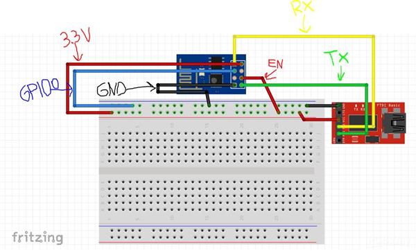
Use a FTDI Board like this:

Be sure that it is 3.3V output!
The ESP01 can't stand more than 3.3V, so with 5V you will damage (permanently) it. Follow the schematics you can find down and upload the code for the ESP8266.
First step: upload a code to the ESP8266;
If you wired it correctly, the upload should go smoothly. Just check "Generic ESP8266 Module" in "Board", and the correct COM port. Be sure to have the library "ESP8266WiFi" before compiling and uploading the code.
If any error occurs, just try connecting the "RST" pin on the ESP to the GND for a second. The re-connect the GPIO0 while uploading the code, and it should go. Just comment if you have any other problems.
Second step: Configuring the EasyIoT Web Interface.
So, that's it. Follow these steps correctly and you shouldn't encounter any problem.

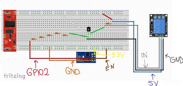
At this point, you should have all your breadboard schematics set up and plugged in. Both the ESP01 and the Relay should be on. Then you can continue;
Click here to download the EasyIoT server. Then run it as administrator, a DOS window should open.
To access the EasyIoT Web Interface you need to put your IP Address (that you can find in cmd with the "ipconfig" command) in your browser.
Paste or write it in the URL tab and press Enter.
An Interface should appear, and you will be asked Username and Password.
They are "admin" and "test" by default, but you can change later if you want. For now, just focus on the following indications.
Now we need to add a new module in Web Interface.
Go to "Configure" -> "Drivers" -> "Virtual Driver" and press the button "AddNode". Enable Virtual Driver and press button "Add Node". An address should appear, something like "N21S0" or similiar. Write it somewhere because we'll need it later.
Press "Close", go back to "Group and Modules" and select "Virtual". Now press "More" and then "Add module". Select the module we added before (you'll recognize it by the address, that is the one you wrote somewhere.
Press "Add" and name it as you like. WHATEVER YOU LIKE.
Change module type from "Generic" to "Digital Output (DO)" and press "Update module"; If you did everything correctly, you should see your module on the front page in the "Virtual" group.
Now it's time to add an Automation Program to the Web Interface.
Click on "More" and "Add new program". Name it, again, AS YOU LIKE. Leave "Cron job" empty. Now press "Edit program" to upload the code to your program, which should be disabled. You should see something like this:
/*
This code is running one time when the program is enabled.
*/
public void setup()
{
}
/*
This code is running periodically when program is enabled.
Cron job determine is running period
*/
public void loop()
{
}
Now paste the code i already uploaded, with the name "Code for the EasyIoT Web Interface". Enable the program and go in EasyIoT Web Interface front page. When you press "ON" and "OFF" in your Web Interface it should turn on and off your Relay.
#include <ESP8266WiFi.h>

const char* ssid = "your-ssid";
const char* password = "your-password";

// Substitute "your-ssid" and "your-password" with your home connection ssid and password.
WiFiServer server(80);

void setup() {
  Serial.begin(115200);
  delay(10);

  // prepare GPIO2
  pinMode(2, OUTPUT);
  digitalWrite(2, 0);

  // Connect to WiFi network
  Serial.println();
  Serial.println();
  Serial.print("Connecting to ");
  Serial.println(ssid);

  WiFi.begin(ssid, password);

  while (WiFi.status() != WL_CONNECTED) {
    delay(500);
    Serial.print(".");
  }
  Serial.println("");
  Serial.println("WiFi connected");

  // Start the server
  server.begin();
  Serial.println("Server started");

  // Print the IP address
  Serial.println(WiFi.localIP());
}

void loop() {
  // Check if a client has connected
  WiFiClient client = server.available();
  if (!client) {
    return;
  }

  // Wait until the client sends some data
  Serial.println("new client");
  while(!client.available()){
    delay(1);
  }

  // Read the first line of the request
  String req = client.readStringUntil('\r');
  Serial.println(req);
  client.flush();

  // Match the request
  int val;
  if (req.indexOf("/gpio/0") != -1)
    val = 0;
  else if (req.indexOf("/gpio/1") != -1)
    val = 1;
  else {
    Serial.println("invalid request");
    client.stop();
    return;
  }

  // Set GPIO2 according to the request
  digitalWrite(2, val);

  client.flush();

  // Prepare the response
  String s = "HTTP/1.1 200 OK\r\nContent-Type: text/html\r\n\r\n<!DOCTYPE HTML>\r\n<html>\r\nGPIO is now ";
  s += (val)?"high":"low";
  s += "</html>\n";

  // Send the response to the client
  client.print(s);
  delay(1);
  Serial.println("Client disonnected");

  // The client will actually be disconnected
  // when the function returns and 'client' object is detroyed
}
const String ESP8266_IP_ADDRESS = "192.168.1.6";

const String MODULE_ADDRESS = "N12S0";

/*

  This code is running one time when program is enabled

*/

public void Setup()

{


  System.Diagnostics.Process.Start("CMD.exe","");


  EventHelper.ModuleChangedHandler((o, m, p) =>

    {

    Console.WriteLine(m.Domain +" "+ m.Address + " in program id "+ Program.ProgramId.ToString()+ " property "+ p.Property + " value " + p.Value);


      if (m.Domain == "Virtual" && m.Address == MODULE_ADDRESS && p.Property == "Sensor.DigitalValue")

        sendCommand(p.Value);


        return true;

    });


}


/*

  This code is running periodicaly when program is enabled.

  Cron job detirmine running period.

*/

public void Run()

{

}


private void sendCommand(string value)

{

  sendToServer("/gpio/"+value);

}


private void sendToServer(String message)

{

  try

  {

  //Console.WriteLine("TCP client command:" + message);


   Int32 port = 80;

   System.Net.Sockets.TcpClient client = new System.Net.Sockets.TcpClient( ESP8266_IP_ADDRESS, port);

   Byte[] data = System.Text.Encoding.ASCII.GetBytes(message);

   System.Net.Sockets.NetworkStream stream = client.GetStream();

   stream.Write(data, 0, data.Length);

   // Close everything.

   stream.Close();

   client.Close();

  }

  catch(Exception e)

  {

    Console.WriteLine(e.StackTrace);

  }

}


Wi-Fi Controlled Relay
- Comments(0)
- Likes(0)
- 0 USER VOTES
- YOUR VOTE 0.00 0.00
- 1
- 2
- 3
- 4
- 5
- 6
- 7
- 8
- 9
- 10
- 1
- 2
- 3
- 4
- 5
- 6
- 7
- 8
- 9
- 10
- 1
- 2
- 3
- 4
- 5
- 6
- 7
- 8
- 9
- 10
- 1
- 2
- 3
- 4
- 5
- 6
- 7
- 8
- 9
- 10
 More by Noshirt
-
 IR Remote for Fan
So, I found this little Fan (it should be at least 10 years old), which was powered by some buttons ...
-
 Arduino Weather Station v1.0 (BMP280)
First version of a very simple weather station made with an Arduino UNO, a BMP280 sensor and a LCD.I...
-
 Wi-Fi Controlled Relay
One day I woke up. I thought, why can't my windows be opened from my pc?! Why I have to get up from ...
-
 Start/Stop Chronometer
Me and my friend are always in competition for something, in every sports, from ski to run, to MTB. ...
-
 Arduino Keyboard V2.0
That's an update for the older version of the project!Now you can play the keyboard on the keys from...
-
 Arduino Keyboard
Didn't know what to do as my first Arduino Project, so i thought of starting out with something litt...
-
-
mammoth-3D SLM Voron Toolhead – Manual Drill & Tap Edition
140 0 0 -
-
AEL-2011 Power Supply Module
654 0 2 -
AEL-2011 50W Power Amplifier
567 0 2 -
-
-
Custom Mechanical Keyboard
769 0 0 -
Tester for Touch Screen Digitizer without using microcontroller
395 2 2 -
Audio reactive glow LED wristband/bracelet with NFC / RFID-Tags
364 0 1 -
-


