
|
arduino IDEArduino
|
7 Segment Clock Using Arduino
What is LED matrix?
An LED matrix or LED display is a large, low-resolution form of dot-matrix display, useful both for industrial and commercial information displays as well as for hobbyist human–machine interfaces. It consists of a 2-D diode matrix with their cathodes joined in rows and their anodes joined in columns (or vice versa).

What is the difference between RGB LED and LED matrix?
RGB matrix panel displays are fundamentally different from other types of panel displays like our Flexible LED Matrix, for instance. Whereas the Flexible LED Matrix is built from a grid of addressable WS2812B LED modules daisy-chained together, the RGB Matrix Panel is actually comprised of standard tri-color LED chips.

Control an 8x8 matrix of LEDs.
Row-column Scanning to control an 8x8 LED Matrix.
LED displays are often packaged as matrixes of LEDs arranged in rows of common anodes and columns of common cathodes, or the reverse. Here's a typical example, and its schematic:
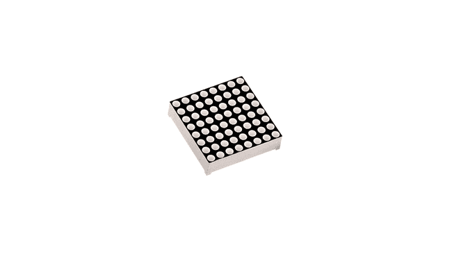
These can be very useful displays. To control a matrix, you connect both its rows and columns to your microcontroller. The columns are connected to the LEDs cathodes (see Figure 1), so a column needs to be LOW for any of the LEDs in that column to turn on. The rows are connected to the LEDs anodes, so the row needs to be HIGH for an individual LED to turn on. If the row and the column are both high or both low, no voltage flows through the LED and it doesn't turn on.

To control an individual LED, you set its column LOW and its row HIGH. To control multiple LEDs in a row, you set the row HIGH, then take the column high, then set the columns LOW or HIGH as appropriate; a LOW column will turn the corresponding LED ON, and a HIGH column will turn it off.

Tip - Pins set to OUTPUT by use of the PinMode command are set to LOW if not otherwise stated
Although there are pre-made LED matrices, you can also make your own matrix from 64 LEDs, using the schematic as shown above.
It doesn't matter which pins of the microcontroller you connect the rows and columns to, because you can assign things in software. Connected the pins in a way that makes wiring easiest. A typical layout is shown below.
Learn how to make an LED matrix controlled by an Arduino.
Scroll down further for step by step photos and more details.
You’ll need the following parts: a prototyping board, (2) 8 pin headers, (8) 200 ohm resistors and (64) red LED bulbs.
Arrange the LEDs in the board according to the design you’ve chosen: either common row anode or common row cathode.
Solder the LEDs to the board, being careful to not to cross any of the anode or cathode leads.
Attach the 8 pin headers to feed power to the LEDs, be sure to place a 200 ohm resistor in line with each positive power lead.
Test your board for continuity with a multimeter.
Attach power to the 8 pin headers.

Today we will be starting our adventure into the deeply complex, yet totally incredible world of LED Matrices. This post is the first of an entire Arduino Matrix Programming series by Circuit Specialists.
First things first, what the heck is an LED matrix, and how does it work??
Simply put, an LED matrix is a grid of lights arranged into rows and columns. LED stands for Light Emitting Diode, so like with other diodes, electricity flows through it in only one direction – from anode(+) to cathode(-); doing so illuminates the light.
By arranging the anodes (positive side) and cathodes (negative side) in a particular way, we can achieve a matrix and call upon each LED individually by sending high and low signals from our arduino device.
Led matrices come in two arrangements. Common-row anode (left) and common-row cathode (right).

The difference between these two configurations determine how you would call on a specific LED. With common-row anode (left), the current sources (positive voltage) are attached to rows A – D. Currents sinks (negative voltage, ground) are attached to columns 1 – 4.
Conversely, with common-row cathode (right) the current sinks (negative voltage, ground) are attached to rows A – D and currents sources (positive voltage) runs through columns 1 – 4.
Applying this knowledge, to light the top-right LED (A,4) in a common-row cathode matrix you would feed positive voltage to column 4 and connect row A to ground.

We will be building this arrangement of common-row cathode matrix in this tutorial.
code
#include <TimeLib.h>
int digit1 = 10;
int digit2 = 11;
int digit3 = 12;
int digit4 = 13;
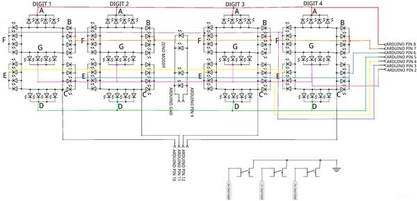
int segA = 8;//Display pin A
int segB = 7;//splay pin b
int segC = 6; //Display pin c
int segD = 5; //Display pin d
int segE = 4; //Display pin e
int segF = 3; //Display pin f
int segG = 2; //Display pin g
int segDP = 9;// Display pin dot
byte SW0 = A0;
byte SW1 = A1;
byte SW2 = A2;
void setup() {
pinMode(segA, OUTPUT);
pinMode(segB, OUTPUT);
pinMode(segC, OUTPUT);
pinMode(segD, OUTPUT);
pinMode(segE, OUTPUT);
pinMode(segF, OUTPUT);
pinMode(segG, OUTPUT);
pinMode(segDP, OUTPUT);
pinMode(digit1, OUTPUT);
pinMode(digit2, OUTPUT);
pinMode(digit3, OUTPUT);
pinMode(digit4, OUTPUT);
Serial.begin(9600);
pinMode(SW0, INPUT);
pinMode(SW1, INPUT);
pinMode(SW2, INPUT);
digitalWrite(SW0, HIGH);
digitalWrite(SW1, HIGH);
digitalWrite(SW2, HIGH);
}
void loop() {
digitalWrite(segDP, HIGH);
int hr = hour();
int timp = ( (hr>12)?(hr%12):hr)*100+minute();
Serial.println(timp);
for(int i = 250 ; i >0 ; i--) {
if (timp > 100) displayNumber01(timp);
else displayNumber02(timp);
}
for(int i = 250 ; i >0 ; i--) {
if (timp > 100) displayNumber03(timp);
else displayNumber04(timp);
}
if (!(digitalRead(SW0))) set_time();
}
void set_time() {
byte minutes1 = 0;
byte hours1 = 0;
byte minutes = minute();
byte hours = hour();
while (!digitalRead(SW0))
{
minutes1=minutes;
hours1=hours;
while (!digitalRead(SW1))
{
minutes++;
if (minutes > 59) minutes = 0;
for(int i = 20 ; i >0 ; i--) {
int timp= hours*100+minutes;
if (timp > 1000) displayNumber01(timp);
else displayNumber02(timp);
}
delay(150);
}
while (!digitalRead(SW2))
{
hours++;
if (hours > 12) hours = 0;
for(int i = 20 ; i >0 ; i--) {
int timp= hours*100+minutes;
if (timp > 1000) displayNumber01(timp);
else displayNumber02(timp);
}
delay(150);
}
for(int i = 20 ; i >0 ; i--) {
displayNumber01(hours*100+minutes);
}
setTime(hours,minutes,0,0,0,0);
delay(150);
}
}
void displayNumber01(int toDisplay) {
#define DISPLAY_BRIGHTNESS 500
#define DIGIT_ON HIGH
#define DIGIT_OFF LOW
for(int digit = 4 ; digit > 0 ; digit--) {
switch(digit) {
case 1:
digitalWrite(digit1, DIGIT_ON);
digitalWrite(segDP, LOW);
break;
case 2:
digitalWrite(digit2, DIGIT_ON);
digitalWrite(segDP, LOW);
break;
case 3:
digitalWrite(digit3, DIGIT_ON);
digitalWrite(segDP, LOW);
break;
case 4:
digitalWrite(digit4, DIGIT_ON);
digitalWrite(segDP, LOW);
break;
}
lightNumber(toDisplay % 10);
toDisplay /= 10;
delayMicroseconds(DISPLAY_BRIGHTNESS);
lightNumber(10);
digitalWrite(digit1, DIGIT_OFF);
digitalWrite(digit2, DIGIT_OFF);
digitalWrite(digit3, DIGIT_OFF);
digitalWrite(digit4, DIGIT_OFF);
}
}
void displayNumber02(int toDisplay) {
#define DISPLAY_BRIGHTNESS 500
#define DIGIT_ON HIGH
#define DIGIT_OFF LOW
for(int digit = 4 ; digit > 0 ; digit--) {
switch(digit) {
case 1:
lightNumber(10);
digitalWrite(segDP, LOW);
break;
case 2:
digitalWrite(digit2, DIGIT_ON);
digitalWrite(segDP, LOW);
break;
case 3:
digitalWrite(digit3, DIGIT_ON);
digitalWrite(segDP, LOW);
break;
case 4:
digitalWrite(digit4, DIGIT_ON);
digitalWrite(segDP, LOW);
break;
}
lightNumber(toDisplay % 10);
toDisplay /= 10;
delayMicroseconds(DISPLAY_BRIGHTNESS);
lightNumber(10);
digitalWrite(digit1, DIGIT_OFF);
digitalWrite(digit2, DIGIT_OFF);
digitalWrite(digit3, DIGIT_OFF);
digitalWrite(digit4, DIGIT_OFF);
}
}
void displayNumber03(int toDisplay) {
#define DISPLAY_BRIGHTNESS 500
#define DIGIT_ON HIGH
#define DIGIT_OFF LOW
for(int digit = 4 ; digit > 0 ; digit--) {
switch(digit) {
case 1:
digitalWrite(digit1, DIGIT_ON);
digitalWrite(segDP, HIGH);
break;
case 2:
digitalWrite(digit2, DIGIT_ON);
digitalWrite(segDP, HIGH);
break;
case 3:
digitalWrite(digit3, DIGIT_ON);
digitalWrite(segDP, HIGH);
break;
case 4:
digitalWrite(digit4, DIGIT_ON);
digitalWrite(segDP, HIGH);
break;
}
lightNumber(toDisplay % 10);
toDisplay /= 10;
delayMicroseconds(DISPLAY_BRIGHTNESS);
lightNumber(10);
digitalWrite(digit1, DIGIT_OFF);
digitalWrite(digit2, DIGIT_OFF);
digitalWrite(digit3, DIGIT_OFF);
digitalWrite(digit4, DIGIT_OFF);
}
}
void displayNumber04(int toDisplay) {
#define DISPLAY_BRIGHTNESS 500
#define DIGIT_ON HIGH
#define DIGIT_OFF LOW
for(int digit = 4 ; digit > 0 ; digit--) {
switch(digit) {
case 1:
lightNumber(10);
digitalWrite(segDP, HIGH);
break;
case 2:
digitalWrite(digit2, DIGIT_ON);
digitalWrite(segDP, HIGH);
break;
case 3:
digitalWrite(digit3, DIGIT_ON);
digitalWrite(segDP, HIGH);
break;
case 4:
digitalWrite(digit4, DIGIT_ON);
digitalWrite(segDP, HIGH);
break;
}
lightNumber(toDisplay % 10);
toDisplay /= 10;
delayMicroseconds(DISPLAY_BRIGHTNESS);
lightNumber(10);
digitalWrite(digit1, DIGIT_OFF);
digitalWrite(digit2, DIGIT_OFF);
digitalWrite(digit3, DIGIT_OFF);
digitalWrite(digit4, DIGIT_OFF);
}
}
void lightNumber(int numberToDisplay) {
#define SEGMENT_ON LOW
#define SEGMENT_OFF HIGH
switch (numberToDisplay){
case 0:
digitalWrite(segA, SEGMENT_ON);
digitalWrite(segB, SEGMENT_ON);
digitalWrite(segC, SEGMENT_ON);
digitalWrite(segD, SEGMENT_ON);
digitalWrite(segE, SEGMENT_ON);
digitalWrite(segF, SEGMENT_ON);
digitalWrite(segG, SEGMENT_OFF);
break;
case 1:
digitalWrite(segA, SEGMENT_OFF);
digitalWrite(segB, SEGMENT_ON);
digitalWrite(segC, SEGMENT_ON);
digitalWrite(segD, SEGMENT_OFF);
digitalWrite(segE, SEGMENT_OFF);
digitalWrite(segF, SEGMENT_OFF);
digitalWrite(segG, SEGMENT_OFF);
break;
case 2:
digitalWrite(segA, SEGMENT_ON);
digitalWrite(segB, SEGMENT_ON);
digitalWrite(segC, SEGMENT_OFF);
digitalWrite(segD, SEGMENT_ON);
digitalWrite(segE, SEGMENT_ON);
digitalWrite(segF, SEGMENT_OFF);
digitalWrite(segG, SEGMENT_ON);
break;
case 3:
digitalWrite(segA, SEGMENT_ON);
digitalWrite(segB, SEGMENT_ON);
digitalWrite(segC, SEGMENT_ON);
digitalWrite(segD, SEGMENT_ON);
digitalWrite(segE, SEGMENT_OFF);
digitalWrite(segF, SEGMENT_OFF);
digitalWrite(segG, SEGMENT_ON);
break;
case 4:
digitalWrite(segA, SEGMENT_OFF);
digitalWrite(segB, SEGMENT_ON);
digitalWrite(segC, SEGMENT_ON);
digitalWrite(segD, SEGMENT_OFF);
digitalWrite(segE, SEGMENT_OFF);
digitalWrite(segF, SEGMENT_ON);
digitalWrite(segG, SEGMENT_ON);
break;
case 5:
digitalWrite(segA, SEGMENT_ON);
digitalWrite(segB, SEGMENT_OFF);
digitalWrite(segC, SEGMENT_ON);
digitalWrite(segD, SEGMENT_ON);
digitalWrite(segE, SEGMENT_OFF);
digitalWrite(segF, SEGMENT_ON);
digitalWrite(segG, SEGMENT_ON);
break;
case 6:
digitalWrite(segA, SEGMENT_ON);
digitalWrite(segB, SEGMENT_OFF);
digitalWrite(segC, SEGMENT_ON);
digitalWrite(segD, SEGMENT_ON);
digitalWrite(segE, SEGMENT_ON);
digitalWrite(segF, SEGMENT_ON);
digitalWrite(segG, SEGMENT_ON);
break;
case 7:
digitalWrite(segA, SEGMENT_ON);
digitalWrite(segB, SEGMENT_ON);
digitalWrite(segC, SEGMENT_ON);
digitalWrite(segD, SEGMENT_OFF);
digitalWrite(segE, SEGMENT_OFF);
digitalWrite(segF, SEGMENT_OFF);
digitalWrite(segG, SEGMENT_OFF);
break;
case 8:
digitalWrite(segA, SEGMENT_ON);
digitalWrite(segB, SEGMENT_ON);
digitalWrite(segC, SEGMENT_ON);
digitalWrite(segD, SEGMENT_ON);
digitalWrite(segE, SEGMENT_ON);
digitalWrite(segF, SEGMENT_ON);
digitalWrite(segG, SEGMENT_ON);
break;
case 9:
digitalWrite(segA, SEGMENT_ON);
digitalWrite(segB, SEGMENT_ON);
digitalWrite(segC, SEGMENT_ON);
digitalWrite(segD, SEGMENT_ON);
digitalWrite(segE, SEGMENT_OFF);
digitalWrite(segF, SEGMENT_ON);
digitalWrite(segG, SEGMENT_ON);
break;
case 10:
digitalWrite(segA, SEGMENT_OFF);
digitalWrite(segB, SEGMENT_OFF);
digitalWrite(segC, SEGMENT_OFF);
digitalWrite(segD, SEGMENT_OFF);
digitalWrite(segE, SEGMENT_OFF);
digitalWrite(segF, SEGMENT_OFF);
digitalWrite(segG, SEGMENT_OFF);
break;
}
}
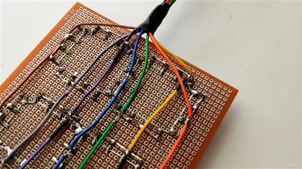
7 Segment Clock Using Arduino
- Comments(0)
- Likes(1)
-
 dvdspelert
Feb 07,2024
- 0 USER VOTES
- YOUR VOTE 0.00 0.00
- 1
- 2
- 3
- 4
- 5
- 6
- 7
- 8
- 9
- 10
- 1
- 2
- 3
- 4
- 5
- 6
- 7
- 8
- 9
- 10
- 1
- 2
- 3
- 4
- 5
- 6
- 7
- 8
- 9
- 10
- 1
- 2
- 3
- 4
- 5
- 6
- 7
- 8
- 9
- 10
 More by Sreeram.zeno
-
 Esp12-F Cluster V1.0
The ESP8266 is a low-cost Wi-Fi microchip, with built-in TCP/IP networking software, and microcontro...
-
 TB6612FNG Motor Driver
The TB6612FNG Motor Driver can control up to two DC motors at a constant current of 1.2A (3.2A peak)...
-
 Sunny Buddy Solar Charger v1.0
This is the Sunny Buddy, a maximum power point tracking (MPPT) solar charger for single-cell LiPo ba...
-
 Diy 74HC4051 8 Channel Mux Breakout Pcb
The 74HC4051; 74HCT4051 is a single-pole octal-throw analog switch (SP8T) suitable for use in analog...
-
 Diy RFM97CW Breakout Pcb
IntroductionLoRa? (standing for Long Range) is a LPWAN technology, characterized by a long range ass...
-
 ProMicro-RP2040 Pcb
The RP2040 is a 32-bit dual ARM Cortex-M0+ microcontroller integrated circuit by Raspberry Pi Founda...
-
 Serial Basic CH340G Pcb
A USB adapter is a type of protocol converter that is used for converting USB data signals to and fr...
-
 Mp3 Shield For Arduino
Hardware OverviewThe centerpiece of the MP3 Player Shield is a VS1053B Audio Codec IC. The VS1053B i...
-
 MRK CAN Shield Arduino
The CAN-BUS Shield provides your Arduino or Redboard with CAN-BUS capabilities and allows you to hac...
-
 AVR ISP Programmer
AVR is a family of microcontrollers developed since 1996 by Atmel, acquired by Microchip Technology ...
-
 Diy Arduino mega Pcb
The Arduino Mega 2560 is a microcontroller board based on the ATmega2560. It has 54 digital input/ou...
-
 Max3232 Breakout Board
MAX3232 IC is extensively used for serial communication in between Microcontroller and a computer fo...
-
 Line Follower Pcb
The Line Follower Array is a long board consisting of eight IR sensors that have been configured to ...
-
 HMC6343 Accelerometer Module
The HMC6343 is a solid-state compass module with tilt compensation from Honeywell. The HMC6343 has t...
-
 RTK2 GPS Module For Arduino
USBThe USB C connector makes it easy to connect the ZED-F9P to u-center for configuration and quick ...
-
 Arduino Explora Pcb
The Arduino Esplora is a microcontroller board derived from the Arduino Leonardo. The Esplora differ...
-
 Diy Stepper Motor Easy Driver
A motor controller is a device or group of devices that can coordinate in a predetermined manner the...
-
 Diy Arduino Pro Mini
The Arduino Pro Mini is a microcontroller board based on the ATmega168 . It has 14 digital input/out...
-
-
TEKTRONIX THS710,THS720,THS730 External Battery Charger with 3D Printed Case
54 1 0 -


