|
arduino IDEArduino
|
|
|
|
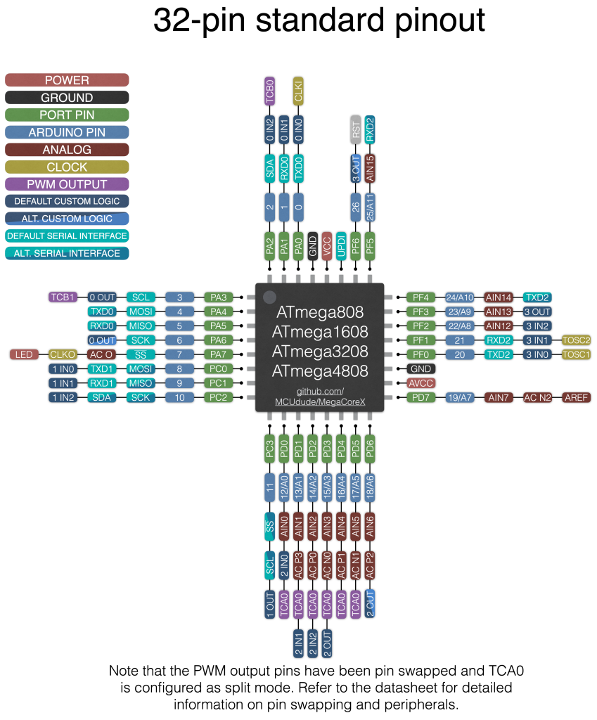
MegaCoreX - the "Core" needed for coding the ATMEGA4808 |
ATMEGA4808 Development board
Breaking out of the Chip Shortage – Attempt #3
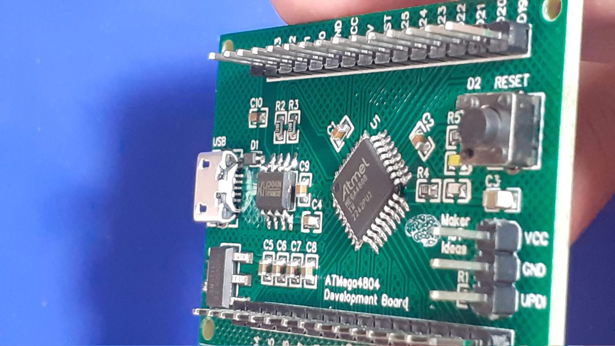
The ATMEGA4808 provides a very attractive solution to replace the trusted ATMEGA328 or standard Arduino UNO /NANO.
These chips are slightly more difficult to get hold of than the ATTiny chips, and cost a little bit more ( about the same as what the ATMEGA328 used to cost before the mess with COVID-19 and resulting supply chain shortages + inflated costs), but they offer all of the functions of the ATMEGA328, with a few other enhancements that will definitely be very useful.
The extras include:
– Hardware interrupts on ALL GPIO pins; This is way more than the standard 2 interrupts on the ATMEGA328 ( We are not talking about the Pin Change interrupts, but real hardware interrupts, that can be triggered on RISING, FALLING, CHANGE, HIGH and LOW state of each pin
– Up to eight (8) PWM pins as opposed to the 6 on the Arduino UNO
– Up to eleven Analog inputs
– An Analog Comparator module
– Configurable Custom Logic (CCL)
– EVENT System (EVSYS)
– Peripheral pin swapping
It is also worth mentioning that these chips have accurate internal oscillators, capable of clocking the chip at up to 20MHz, further reducing the number of external components required to get a minimal configuration running…
The Prototype PCB
While I have had a Nano Every “Clone” lying in a drawer for quite a while now, I did not really pay a lot of attention to it. That was, until I needed an ATMEGA328 for a project, and could not find any for sale, or at least at a price that I was willing to pay for it… That incident was the spark that ignited this entire exercise, to find a suitable replacement…
The Nano Every “Clone” in my possession, used the ATMEGA 4808 chip and turned out to be the Thinary Nano 4808. I had quite a lot of problems with the provided core, as well as getting peripherals like I2c and SPI to work. This led to further investigations, and finally, I decided on building my own and to use the MCUdude/MegaCoreX Arduino Core to program it.
This led to the following prototype:
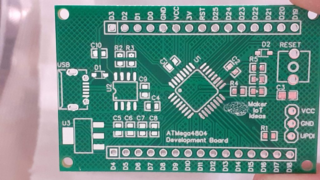 ATMEGA4808 Development board prototype
I did not bother with too much detail on the silk screen here, as the goal was to get a working board, test it, and then later, design a refined PCB.
What is important to note is that the board runs at 5v, but provides a single 3.3v output as well. Logic levels on the GPIO is also 5v. Use level converters for 3.3v only add-ons…
The MEGA4808 is programmed via UPDI, so we have a UPDI Header on the right-hand side of the PCB. It is also possible to use the Optiboot Bootloader, to flash the board in true Arduino style through a USB connection to a computer.
A CH340N USB-to-Serial converter chip is used instead of the CH340G that is common on the UNO clones. The CH340N provides only the USB D+ D- signals, as well as Rx, TX and RTS. RTS is being used to auto-reset the chip after flashing…
In comparison to the CH340G, which also required a crystal oscillator, but provides all the modem control signals, which, are usually not even broken out, the CH340N made much more sense.
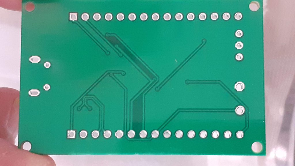 PCB Bottom.
A power LED, as well as an indicator LED on pin 7, was also included.
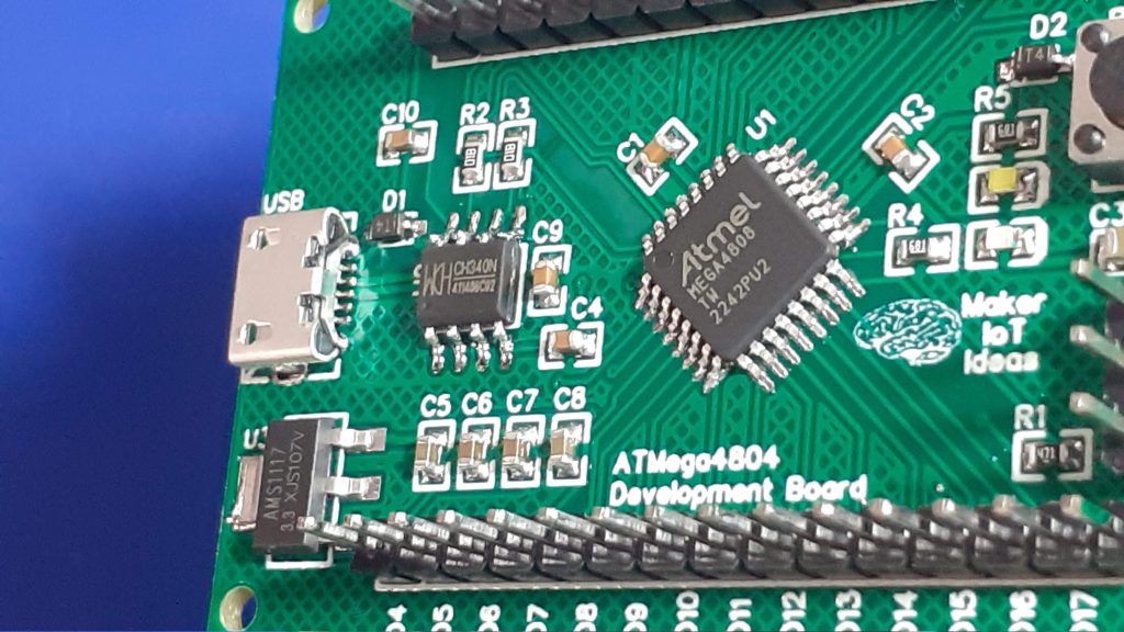 Assembled PCB, Top Layer.
Assembly and Soldering
I normally assemble all my projects by hand and reflow-solder them with a hot plate. for this project, I decided to do things a bit differently, which ended up being a bit awkward, but still resulted in a perfectly useable PBC.
As you will know by now, I only do written articles, as I don’t consider myself ready for the Youtube and video thing, as well as because I believe a well-written article, with detailed pictures, is easier to understand than a video…
Well, today, we will have both… This article, with its writeups and pictures, as well as a short assembly and soldering video, with no sound, sped up 5x, as I did not want to bore anyone with a 25-minute silent video…
Let us begin then…
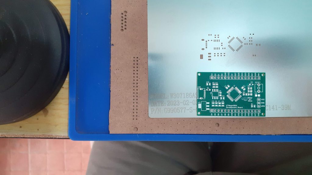 PCB and Stencil
We start with a blank PCB and the laser-cut stainless steel stencil that I got from PCBWay.
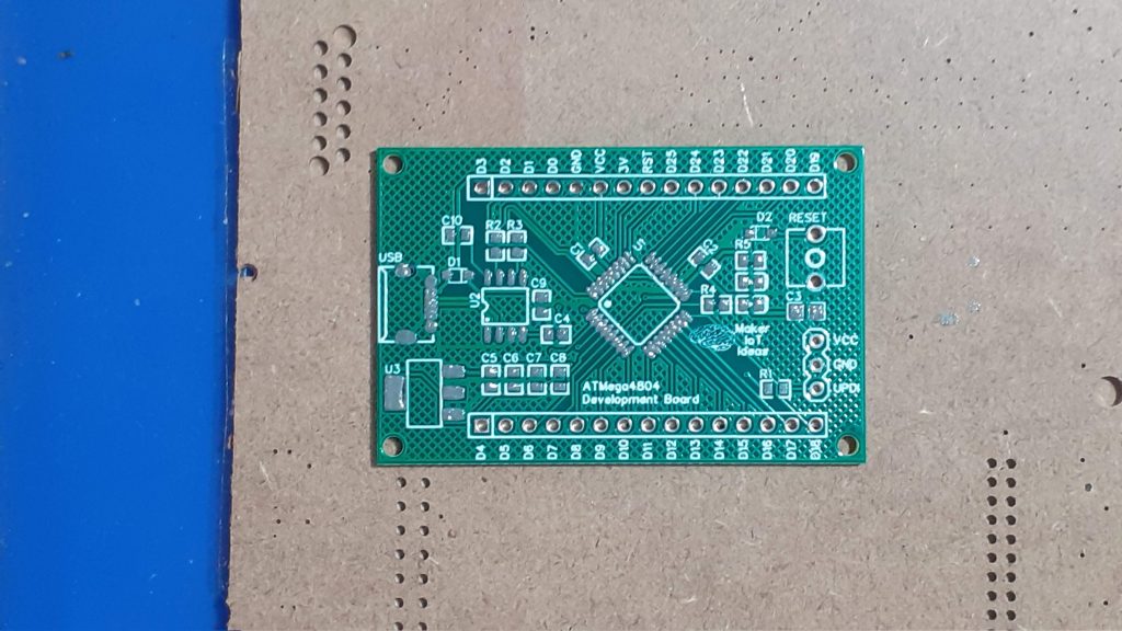 Solder paste applied
Solder paste is then applied with the stencil and a scraper, and afterwards, the stencil is removed… The PCB is now ready for component placement…
From here on, we will go to the video footage… showing component placement, with some awkwardness due to the camera being in the way, as well as hot-air soldering, with the same awkwardness, as I was forced to use my right hand ( I am left-handed), not to block the camera view…
Begin quite new to the video thing, I have also not quite figured out the editing software, so the video is in native resolution… not zoomed…
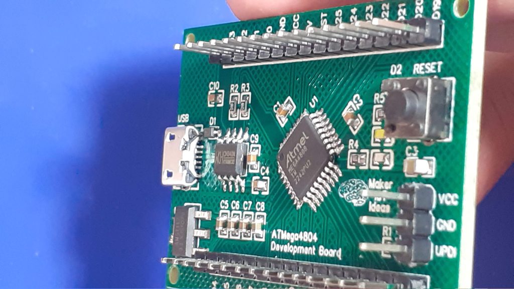 After assembly
After assembly, I checked for solder bridges and was quite happy that there were none. This also meant that the board worked perfectly the first time around… as it should…
Picture Gallery
 Blank PCB – Top
 Blank PCB – Bottom
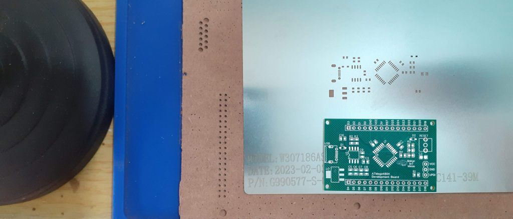 PCB and Stencil
 After Solderpaste application
 After assembly, inspection
 After assembly, inspection
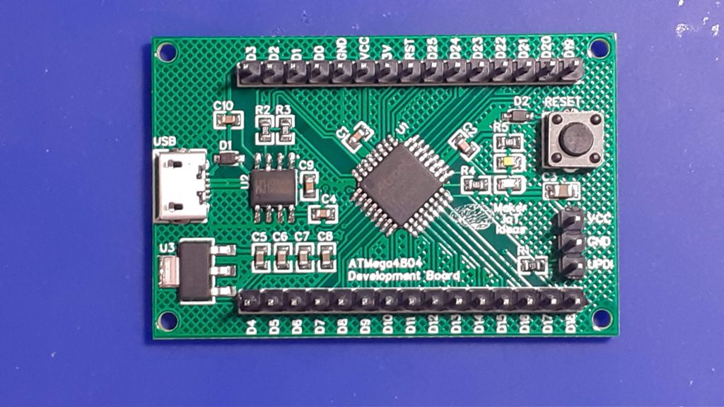 Completed PCB, Top
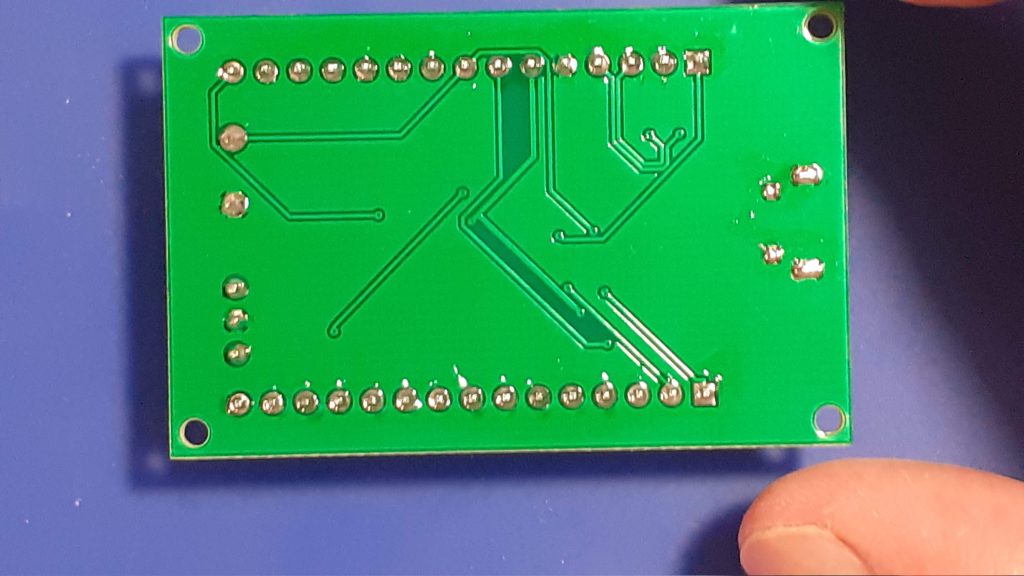 Completed PBC, Bottom

ATMEGA4808 Development board
*PCBWay community is a sharing platform. We are not responsible for any design issues and parameter issues (board thickness, surface finish, etc.) you choose.
- Comments(0)
- Likes(3)
-
 Engineer
Mar 22,2025
-
 Anthony Pedotto
Feb 22,2025
-
 Engineer
Mar 02,2023
- 0 USER VOTES
- YOUR VOTE 0.00 0.00
- 1
- 2
- 3
- 4
- 5
- 6
- 7
- 8
- 9
- 10
- 1
- 2
- 3
- 4
- 5
- 6
- 7
- 8
- 9
- 10
- 1
- 2
- 3
- 4
- 5
- 6
- 7
- 8
- 9
- 10
- 1
- 2
- 3
- 4
- 5
- 6
- 7
- 8
- 9
- 10
 More by Jean Redelinghuys MakerIoT2020
-
 PCB_MCP23008_2023-10-08
MCP23008 BreakoutI designed this breakout to assist me during prototyping my next version of the “RP...
-
 PCB_XiaoRP2040-Mouse-REV2
Xiao RP2040 Joystick Mouse – revision 2.00Revision 1.0 of the ProjectOver the last few months, I hav...
-
 Multi Purpose IO Card
Multi-Purpose IO CardWhen we are working on a prototype, we always need access to pushbuttons, encod...
-
 Variable Voltage Power Module
Powering electronics projects are always challenging. This Variable vol...
Variable Voltage Power Module
Variable Voltage Power ModulePowering electronics projects are always challenging. This Variable vol...
-
 I2C Matrix Keypad
An I2C Matrix KeypadThe completed I2C Matrix KeypadIn a previous post this month I introduced my 4×4...
-
 ESP32-S Development Board, in "Arduino Uno" form factor
UPDATE 24/06/2023:This board now has a Hardware Revision 2.0 available. It is the same board but wit...
-
 W307186ASC94_Gerber_PCB_USB-Ports
USB Power Supply ModuleUSB Ports are quite handy to power all our day-to-day electronic devices, but...
-
 Atmega 328P based PWM controller Card
ATMega 328P Based PWM controller CardAs part of my recent ESP-12E I2C Base Board project, I designed...
-
 W307186ASC71_Gerber_PCB_ESP-Now Remote
Today we will look at the remote control unit for the Robotic Toy Car – Part 6.The project is close ...
-
 W307186ASV69_Gerber_PCB_Robot-Car-MCU-Board Prototype
In our last project, we started working on repurposing an old toy car. In this part, Robot Toy Car –...
-
 W307186ASV62_Gerber_PCB_DUAL-H-Bridge
by makeriot2020 on May 27, 2022Many of us have old toys laying around the house, they belong to ou...
-
 CAN-BUS Breakout
Breadboard Compatible CAN-BUS Breakout ModuleWhat is this:Some of us have already used the commonly ...
-
 RA-02 Breakout with Level converters
Breadboard and beginner-friendly RA-02 Breakout ModuleMost Makers and electronics enthusiasts may al...
-
 ATMEGA328P Module with integrated LoRa and CAN Bus
ATMEGA328P Module with integrated LoRa and CAN-BUSINTRODUCTIONIn my quest to perfect my LoRa telemet...
-
 Sx127x-Ra-02-Test-Module with ATMEGA328P-AU
SX127x LoRa/FSK/OOK Prototype Radio BoardI recently had a requirement to do some automation/telemetr...
-
 USB-ASP Programmer ATMEGA8
Build your own USB-ASP Programmer CloneBymakeriot2020 FEB 21, 2022 Arduino, ASP programmerUsing mor...
-
 ATTiny1616-LIGHT-Controller-with-CAN_B_PCB_ATTiny1616-LIGHT-Controller-with-C_2024-09-11
Assembly of the ATTiny1616 Can bus controller PCBThe Assembly of the ATTiny1616 Can Bus Controller P...
-
 ATTiny1616QFN-CAN-Remote-Neopixel-Ligh_PCB_ATTiny1616QFN-CAN-Remote-Neopixel-2024-09-11_2024-09-11
NeoPixel CAN-Bus Module with local controlAs part of my current project to add NeoPixels to the cabi...
-
-
AEL-2011 Power Supply Module
545 0 2 -
AEL-2011 50W Power Amplifier
505 0 2 -
-
-
Custom Mechanical Keyboard
706 0 0 -
Tester for Touch Screen Digitizer without using microcontroller
337 2 2 -
Audio reactive glow LED wristband/bracelet with NFC / RFID-Tags
317 0 1 -
-
-


