|
ATMEGA32-16AIMicrochip Technology
|
x 1 | |

|
106CKR063MIllinois Capacitor
|
x 1 | |

|
741C083510JPCTS Resistor Products
|
x 1 | |

|
USB3505-30-A-KITGCT
|
x 1 |

|
arduino IDEArduino
|
ATMEGA 32U-4 Standlone Board
AVR is a family of microcontrollers developed since 1996 by Atmel, acquired by Microchip Technology in 2016. These are modified Harvard architecture 8-bit RISC single-chip microcontrollers. AVR was one of the first microcontroller families to use on-chip flash memory for program storage, as opposed to one-time programmable ROM, EPROM, or EEPROM used by other microcontrollers at the time.

AVR microcontrollers find many applications as embedded systems. They are especially common in hobbyist and educational embedded applications, popularized by their inclusion in many of the Arduino line of open hardware development boards.
The AVR architecture was conceived by two students at the Norwegian Institute of Technology (NTH),[1] Alf-Egil Bogen and Vegard Wollan.

Atmel says that the name AVR is not an acronym and does not stand for anything in particular. The creators of the AVR give no definitive answer as to what the term "AVR" stands for.
However, it is commonly accepted that AVR stands for Alf and Vegard's RISC processor.[4] Note that the use of "AVR" in this article generally refers to the 8-bit RISC line of Atmel AVR microcontrollers.
The original AVR MCU was developed at a local ASIC house in Trondheim, Norway, called Nordic VLSI at the time, now Nordic Semiconductor, where Bogen and Wollan were working as students.[citation needed] It was known as a μRISC (Micro RISC)[5] and was available as silicon IP/building block from Nordic VLSI.

When the technology was sold to Atmel from Nordic VLSI, the internal architecture was further developed by Bogen and Wollan at Atmel Norway, a subsidiary of Atmel. The designers worked closely with compiler writers at IAR Systems to ensure that the AVR instruction set provided efficient compilation of high-level languages.
Among the first of the AVR line was the AT90S8515, which in a 40-pin DIP package has the same pinout as an 8051 microcontroller, including the external multiplexed address and data bus. The polarity of the RESET line was opposite (8051's having an active-high RESET, while the AVR has an active-low RESET), but other than that the pinout was identical.

The AVR 8-bit microcontroller architecture was introduced in 1997. By 2003, Atmel had shipped 500 million AVR flash microcontrollers.[8] The Arduino platform, developed for simple electronics projects, was released in 2005 and featured ATmega8 AVR microcontrollers.
EEPROM
Almost all AVR microcontrollers have internal EEPROM for semi-permanent data storage. Like flash memory, EEPROM can maintain its contents when electrical power is removed.
In most variants of the AVR architecture, this internal EEPROM memory is not mapped into the MCU's addressable memory space. It can only be accessed the same way an external peripheral device is, using special pointer registers and read/write instructions, which makes EEPROM access much slower than other internal RAM.
However, some devices in the SecureAVR (AT90SC) family[11] use a special EEPROM mapping to the data or program memory, depending on the configuration. The XMEGA family also allows the EEPROM to be mapped into the data address space.
Since the number of writes to EEPROM is limited – Atmel specifies 100,000 write cycles in their datasheets – a well designed EEPROM write routine should compare the contents of an EEPROM address with desired contents and only perform an actual write if the contents need to be changed.
Program execution
Atmel's AVRs have a two-stage, single-level pipeline design. This means the next machine instruction is fetched as the current one is executing. Most instructions take just one or two clock cycles, making AVRs relatively fast among eight-bit microcontrollers.
The AVR processors were designed with the efficient execution of compiled C code in mind and have several built-in pointers for the task.
SPI

6- and 10-pin ISP header diagrams
The in-system programming (ISP) programming method is functionally performed through SPI, plus some twiddling of the Reset line. As long as the SPI pins of the AVR are not connected to anything disruptive, the AVR chip can stay soldered on a PCB while reprogramming. All that is needed is a 6-pin connector and programming adapter. This is the most common way to develop with an AVR.
The Atmel-ICE device or AVRISP mkII (Legacy device) connects to a computer's USB port and performs in-system programming using Atmel's software.

AVRDUDE (AVR Downloader/UploaDEr) runs on Linux, FreeBSD, Windows, and Mac OS X, and supports a variety of in-system programming hardware, including Atmel AVRISP mkII, Atmel JTAG ICE, older Atmel serial-port based programmers, and various third-party and "do-it-yourself" programmers.
PDI
The Program and Debug Interface (PDI) is an Atmel proprietary interface for external programming and on-chip debugging of XMEGA devices. The PDI supports high-speed programming of all non-volatile memory (NVM) spaces; flash, EEPROM, fuses, lock-bits and the User Signature Row. This is done by accessing the XMEGA NVM controller through the PDI interface, and executing NVM controller commands. The PDI is a 2-pin interface using the Reset pin for clock input (PDI_CLK) and a dedicated data pin (PDI_DATA) for input and output.[18]
UPDI

The Unified Program and Debug Interface (UPDI) is a one-wire interface for external programming and on-chip debugging of newer ATtiny and ATmega devices. The Atmel-ICE and PICkit 4 are capable of programming UPDI chips. It is also possible to use an Arduino thanks to jtag2updi.
High-voltage serial
High-voltage serial programming (HVSP)[20] is mostly the backup mode on smaller AVRs. An 8-pin AVR package does not leave many unique signal combinations to place the AVR into a programming mode. A 12-volt signal, however, is something the AVR should only see during programming and never during normal operation. The high voltage mode can also be used in some devices where the reset pin has been disabled by fuses.
Atmel Studio C Program
#ifndef F_CPU
#define F_CPU 16000000UL // 16 MHz clock speed
#endif
#include <avr/io.h>
#include <util/delay.h>
int main(void)
{
DDRC = 0xFF; //Nakes PORTC as Output
while(1) //infinite loop
{
PORTC = 0xFF; //Turns ON All LEDs
_delay_ms(1000); //1 second delay
PORTC= 0x00; //Turns OFF All LEDs
_delay_ms(1000); //1 second delay
}
}
DDRC = 0xFF makes all pins on PORTC as output pins
PORTC = 0xFF makes all pins on PORTC Logic High (5V)
PORTC = 0x00 makes all pins on PORTC Logic Low (0V)
_delay_ms(1000) provides 1000 milliseconds delay.
while(1) makes an infinite loop
You have seen that PORT registers are used to write data to ports. Similarly to read data from ports PIN registers are used. It stand for Port Input Register. eg : PIND, PINB
You may like to set or reset individual pins of PORT or DDR registers or to know the status of a specific bit of PIN register. There registers are not bit addressable, so we can’t do it directly but we can do it through program. To make 3ed bit (PC2) of DDRC register low we can use DDRC &= ~(1<<PC2). (1<<PC2) generates the binary number 00000100, which is complemented 11111011 and ANDed with DDRC register, which makes the 3ed bit 0. Similarly DDRC |= (1<<PC2) can be used set the 3ed bit (PC2) of DDRC register and to read 3ed bit (PC2) we can use PINC & (1<<PC2). Similarly we can set or reset each bit of DDR or PORT registers and able to know the logic state of a particular bit of PIN register.
1. Download and Install Atmel Studio. You can download Atmel Studio from Atmel’s Website.
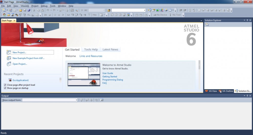
2. Open Atmel Studio

After Opening Atmel Studio
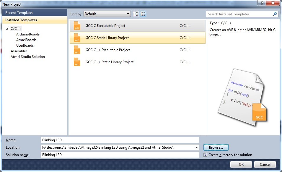
3. Select New Project

Opening New Project – Atmel Studio
4. Select GCC C Executable Project, give a project name, solution name, location in which project is to be saved and click OK.
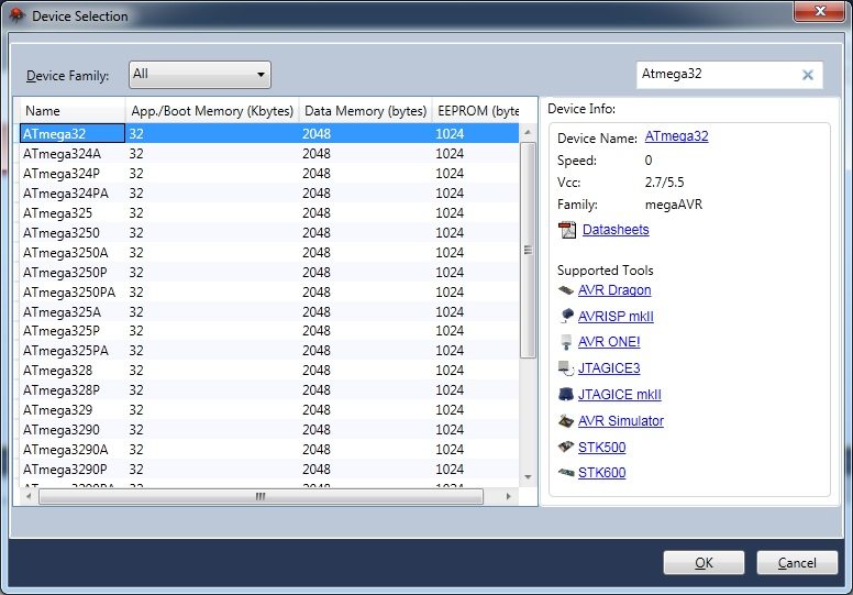
5. Selecting Microcontroller

Selecting Microcontroller – Atmel Studio
Choose the microcontroller that you are going to use, here we are using Atmega32. Then Click OK.
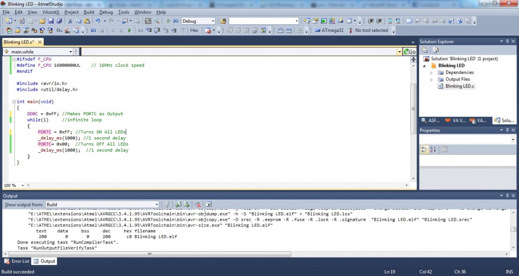
6. Enter the Program

Enter the Program – Atmel Studio
7. Then click on Build >> Build Solution or Press F7 to generate the hex file.
Circuit Diagram
Blinking LED using Atmega32 AVR Microcontroller and Atmel Studio
LEDs are connected to PORTC and current limiting resistors are used to limit current through them. 16 MHz crystal is used to provide clock for the Atmega32 microcontroller and 22pF capacitors are used to stabilize the operation of crystal. The 10μF capacitor and 10KΩ resistor is used to provide Power On Reset (POR) to the device. When the power is switched ON, voltage across capacitor will be zero so the device resets (since reset is active low), then the capacitor charges to VCC and the reset will be disabled. 30th pin (AVCC) of Atmega32 should be connected to VCC if you are using PORTA, since it is the supply voltage pin for PORT A.
Atmel Studio C Program

ATMEGA 32U-4 Standlone Board
*PCBWay community is a sharing platform. We are not responsible for any design issues and parameter issues (board thickness, surface finish, etc.) you choose.
- Comments(0)
- Likes(0)
- 0 USER VOTES
- YOUR VOTE 0.00 0.00
- 1
- 2
- 3
- 4
- 5
- 6
- 7
- 8
- 9
- 10
- 1
- 2
- 3
- 4
- 5
- 6
- 7
- 8
- 9
- 10
- 1
- 2
- 3
- 4
- 5
- 6
- 7
- 8
- 9
- 10
- 1
- 2
- 3
- 4
- 5
- 6
- 7
- 8
- 9
- 10
 More by Sreeram.zeno
-
 Esp12-F Cluster V1.0
The ESP8266 is a low-cost Wi-Fi microchip, with built-in TCP/IP networking software, and microcontro...
-
 TB6612FNG Motor Driver
The TB6612FNG Motor Driver can control up to two DC motors at a constant current of 1.2A (3.2A peak)...
-
 Sunny Buddy Solar Charger v1.0
This is the Sunny Buddy, a maximum power point tracking (MPPT) solar charger for single-cell LiPo ba...
-
 Diy 74HC4051 8 Channel Mux Breakout Pcb
The 74HC4051; 74HCT4051 is a single-pole octal-throw analog switch (SP8T) suitable for use in analog...
-
 Diy RFM97CW Breakout Pcb
IntroductionLoRa? (standing for Long Range) is a LPWAN technology, characterized by a long range ass...
-
 ProMicro-RP2040 Pcb
The RP2040 is a 32-bit dual ARM Cortex-M0+ microcontroller integrated circuit by Raspberry Pi Founda...
-
 Serial Basic CH340G Pcb
A USB adapter is a type of protocol converter that is used for converting USB data signals to and fr...
-
 Mp3 Shield For Arduino
Hardware OverviewThe centerpiece of the MP3 Player Shield is a VS1053B Audio Codec IC. The VS1053B i...
-
 MRK CAN Shield Arduino
The CAN-BUS Shield provides your Arduino or Redboard with CAN-BUS capabilities and allows you to hac...
-
 AVR ISP Programmer
AVR is a family of microcontrollers developed since 1996 by Atmel, acquired by Microchip Technology ...
-
 Diy Arduino mega Pcb
The Arduino Mega 2560 is a microcontroller board based on the ATmega2560. It has 54 digital input/ou...
-
 Max3232 Breakout Board
MAX3232 IC is extensively used for serial communication in between Microcontroller and a computer fo...
-
 Line Follower Pcb
The Line Follower Array is a long board consisting of eight IR sensors that have been configured to ...
-
 HMC6343 Accelerometer Module
The HMC6343 is a solid-state compass module with tilt compensation from Honeywell. The HMC6343 has t...
-
 RTK2 GPS Module For Arduino
USBThe USB C connector makes it easy to connect the ZED-F9P to u-center for configuration and quick ...
-
 Arduino Explora Pcb
The Arduino Esplora is a microcontroller board derived from the Arduino Leonardo. The Esplora differ...
-
 Diy Stepper Motor Easy Driver
A motor controller is a device or group of devices that can coordinate in a predetermined manner the...
-
 Diy Arduino Pro Mini
The Arduino Pro Mini is a microcontroller board based on the ATmega168 . It has 14 digital input/out...
-
-
mammoth-3D SLM Voron Toolhead – Manual Drill & Tap Edition
229 0 0 -
-
AEL-2011 Power Supply Module
755 0 2 -
AEL-2011 50W Power Amplifier
627 0 2 -
-
-
Custom Mechanical Keyboard
822 0 0 -
Tester for Touch Screen Digitizer without using microcontroller
448 2 2 -
Audio reactive glow LED wristband/bracelet with NFC / RFID-Tags
399 0 1 -
-


