
|
ESP8266-DEVKITC-02D-FEspressif Systems
|
x 1 | |

|
DHT22AMAZON
|
x 1 | |

|
MQ135 air quality sensor module |
x 1 | |

|
SD Card Module |
x 1 | |

|
40 Pin Jumper Wires Female to Female 20cm |
x 1 |

|
arduino IDEArduino
|
Nodemcu Data Logger
You mostly have seen Data logging web server with real-time graphs and tables on ThingSpeak and other IoT platforms. But we can also create our own webserver and can update the data in real-time, we previously created many webservers using different boards. Here we will also create ESP8266 Web Server Data Logger using DHT11 Sensor. Here the temperature and humidity data will be updated on the webpage using AJAX.
AJAX (Asynchronous JavaScript and XML) allows for automatic updating of websites by sharing tiny volumes of data with the server in the background without refreshing the complete webpage. This ensures that portions of a web page will be changed without reloading the whole website. So let’s get started!
Components Required
NodeMCU ESP8266
DHT11 Sensor
Jumper Wires
DHT11 sensor is used to measure temperature and humidity and generally used to create weather stations.
Circuit Diagram
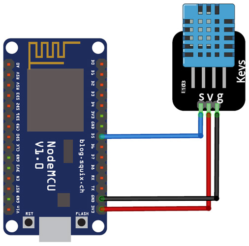
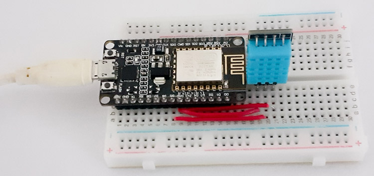
Wiring the DHT11 to the NodeMCU is easy. VCC and GND pins of DHT11 is connected to 3.3V and GND NodeMCU while the Data pin of DHT is connected to D5 (GPIO 14) pin of NodeMCU.
Programming NodeMCU ESP8266 for Data logging
Before moving directly on coding, install required libraries, the ESP8266 libraries are pre-installed on IDE; you only need to install the DHT11 library
After installing the library, including all the required libraries.
#include <ESP8266WiFi.h>
#include <WiFiClient.h>
#include <ESP8266WebServer.h>
#include "DHT.h"
Now in the next lines, enter your Wi-Fi name and Password.
const char* ssid = "Wi-Fi Name";
const char* password = "Password";
Then define the type of DHT sensor and the pin where the sensor is connected. If you are using DHT22, then change the DHT type to DHT22. In my case, the DHT sensor is connected to the GPIO14 (D5) of NodeMCU.
#define LED 2 //Onboard LED
#define DHTTYPE DHT11 // DHT 11
uint8_t DHTPin = 14;
DHT dht(DHTPin, DHTTYPE);
The handleRoot function is executed when we open the Webpage inbrowser using the NodeMCU IP address.
void handleRoot()
{
String s = MAIN_page; //Read HTML contents
server.send(200, "text/html", s); //Send web page
}
The next function that is readData() is used to read the data from the DHT11 sensor and send it to the Webpage. In this loop, NodeMCU stores the DHT11 values into two float variables: temperature & humidity, after this it converts the float variables into the string and store their data into another string variable ‘Data’ and send this to Webpage whenever requested.
void readData()
{
String data = "{\"Temperature\":\""+ String(temperature) +"\", \"Humidity\":\""+ String(humidity) +"\"}";
digitalWrite(LED,!digitalRead(LED));
server.send(200, "text/plane", data);
delay(2000);
temperature = dht.readTemperature();
humidity = dht.readHumidity();
Serial.print(humidity, 1);
Serial.print(temperature, 1);
}
Inside the void setup() function, we initialized the baud rate, DHT sensor using .begin() function, Webpage using server.begin() function and then connect the module with the Wi-Fi using the Wi-Fi name and password.
Serial.begin(115200);
pinMode(DHTPin, INPUT);
dht.begin();
WiFi.begin(ssid, password);
server.begin();
The first function is used to call the 'handleRoot' function when a client requests URI (Uniform Resource Identifier) "/" while the second function is used to call the 'readData' function when a POST request is made to URI "/readData"
server.on("/", handleRoot);
server.on("/readData", readData);
The void loop() function continuously listen for HTTP requests from clients
void loop(void)
{
server.handleClient();
}
Data logging
A common use for IoT devices like the ESP8266 is monitoring sensors. Using the code in the previous example, we can request the time, and save some sensor values to a file. If we run a server as well, we can show this data in a pretty graph in a webpage.
Temperature logger
In the following example, we'll use a DS18S20 temperature sensor to log the temperature over time and save it to the SPIFFS. It can then be displayed in a graph in the browser.
Installing libraries
First, download the Dallas Temperature library by Miles Burton and the OneWire library by Jim Studt: Go to Sketch > Include Library ... > Manage Libraries and search for 'Dallas Temperature' and 'OneWire' (make sure you download the correct version).
Hardware
Connect the ground of the DS18S20 temperature sensor (pin 1) to the ground of the ESP, connect the data pin (pin 2) to GPIO5, and VCC (pin 3) to the 3.3V of the ESP. Finally, connect a 4k7Ω resistor between the data pin and VCC.
Libraries, constants and globals
#include <OneWire.h>
#include <DallasTemperature.h>
#include <ESP8266WiFi.h>
#include <ESP8266WiFiMulti.h>
#include <WiFiUdp.h>
#include <ArduinoOTA.h>
#include <ESP8266WebServer.h>
#include <ESP8266mDNS.h>
#include <FS.h>
#define ONE_HOUR 3600000UL
#define TEMP_SENSOR_PIN 5
OneWire oneWire(TEMP_SENSOR_PIN); // Set up a OneWire instance to communicate with OneWire devices
DallasTemperature tempSensors(&oneWire); // Create an instance of the temperature sensor class
ESP8266WebServer server(80); // Create a webserver object that listens for HTTP request on port 80
File fsUploadFile; // a File variable to temporarily store the received file
ESP8266WiFiMulti wifiMulti; // Create an instance of the ESP8266WiFiMulti class, called 'wifiMulti'
const char *OTAName = "ESP8266"; // A name and a password for the OTA service
const char *OTAPassword = "esp8266";
const char* mdnsName = "esp8266"; // Domain name for the mDNS responder
WiFiUDP UDP; // Create an instance of the WiFiUDP class to send and receive UDP messages
IPAddress timeServerIP; // The time.nist.gov NTP server's IP address
const char* ntpServerName = "time.nist.gov";
const int NTP_PACKET_SIZE = 48; // NTP time stamp is in the first 48 bytes of the message
byte packetBuffer[ NTP_PACKET_SIZE]; // A buffer to hold incoming and outgoing packets
The only new things here are the OneWire and DallasTemperature libraries, to get the temperature from the sensor.
Setup
void setup() {
Serial.begin(115200); // Start the Serial communication to send messages to the computer
delay(10);
Serial.println("\r\n");
tempSensors.setWaitForConversion(false); // Don't block the program while the temperature sensor is reading
tempSensors.begin(); // Start the temperature sensor
if (tempSensors.getDeviceCount() == 0) {
Serial.printf("No DS18x20 temperature sensor found on pin %d. Rebooting.\r\n", TEMP_SENSOR_PIN);
Serial.flush();
ESP.reset();
}
startWiFi(); // Start a Wi-Fi access point, and try to connect to some given access points. Then wait for either an AP or STA connection
startOTA(); // Start the OTA service
startSPIFFS(); // Start the SPIFFS and list all contents
startMDNS(); // Start the mDNS responder
startServer(); // Start a HTTP server with a file read handler and an upload handler
startUDP(); // Start listening for UDP messages to port 123
WiFi.hostByName(ntpServerName, timeServerIP); // Get the IP address of the NTP server
Serial.print("Time server IP:\t");
Serial.println(timeServerIP);
sendNTPpacket(timeServerIP);
}
In the setup, there's not much new either, we just start the temperature sensor, and check if we can communicate with it. If no temperature sensor is found, the ESP resets.
Getting the temperature from the sensor may take some time (up to 750ms). We don't want our loop to take longer than a couple of milliseconds, so we can't wait 750ms. If we did, the HTTP server etc. would start to misbehave.
The solution is to request the temperature first. The sensor will then start reading the analog temperature, and stores it in its memory. In the meantime, the loop just keeps on running, the server refreshes etc. After 750ms, we contact the sensor again, and read the temperature from its memory.
To tell the library that we don't want to wait for the analog to digital conversion of the sensor, we use setWaitForConversion.
Loop
const unsigned long intervalNTP = ONE_HOUR; // Update the time every hour
unsigned long prevNTP = 0;
unsigned long lastNTPResponse = millis();
const unsigned long intervalTemp = 60000; // Do a temperature measurement every minute
unsigned long prevTemp = 0;
bool tmpRequested = false;
const unsigned long DS_delay = 750; // Reading the temperature from the DS18x20 can take up to 750ms
uint32_t timeUNIX = 0; // The most recent timestamp received from the time server
void loop() {
unsigned long currentMillis = millis();
if (currentMillis - prevNTP > intervalNTP) { // Request the time from the time server every hour
prevNTP = currentMillis;
sendNTPpacket(timeServerIP);
}
uint32_t time = getTime(); // Check if the time server has responded, if so, get the UNIX time
if (time) {
timeUNIX = time;
Serial.print("NTP response:\t");
Serial.println(timeUNIX);
lastNTPResponse = millis();
} else if ((millis() - lastNTPResponse) > 24UL * ONE_HOUR) {
Serial.println("More than 24 hours since last NTP response. Rebooting.");
Serial.flush();
ESP.reset();
}
if (timeUNIX != 0) {
if (currentMillis - prevTemp > intervalTemp) { // Every minute, request the temperature
tempSensors.requestTemperatures(); // Request the temperature from the sensor (it takes some time to read it)
tmpRequested = true;
prevTemp = currentMillis;
Serial.println("Temperature requested");
}
if (currentMillis - prevTemp > DS_delay && tmpRequested) { // 750 ms after requesting the temperature
uint32_t actualTime = timeUNIX + (currentMillis - lastNTPResponse) / 1000;
// The actual time is the last NTP time plus the time that has elapsed since the last NTP response
tmpRequested = false;
float temp = tempSensors.getTempCByIndex(0); // Get the temperature from the sensor
temp = round(temp * 100.0) / 100.0; // round temperature to 2 digits
Serial.printf("Appending temperature to file: %lu,", actualTime);
Serial.println(temp);
File tempLog = SPIFFS.open("/temp.csv", "a"); // Write the time and the temperature to the csv file
tempLog.print(actualTime);
tempLog.print(',');
tempLog.println(temp);
tempLog.close();
}
} else { // If we didn't receive an NTP response yet, send another request
sendNTPpacket(timeServerIP);
delay(500);
}
server.handleClient(); // run the server
ArduinoOTA.handle(); // listen for OTA events
}
The loop looks a lot more complex, but it's actually pretty simple. It's all based on Blink Without Delay.
There's two things going on:
Overview
This is a calibrated digital temperature and humidity module with onboard sensor DHT22 (AM2302), which features higher accuracy and a wider measuring range than DHT11.
It can be used for detecting ambient temperature and humidity, through the standard single-wire interface.
Specification
Temperature
Resolution : 0.1°C
Accuracy : ±0.5℃
Measuring range : -40°C ~ 80°C
Humidity
Resolution : 0.1%RH
Accuracy : ±2%RH (25°C)
Measuring range : 0%RH ~ 99.9%RH
Operating voltage : 3.3V ~ 5.5 V
Recommended storage condition
Temperature : 10°C ~40°C
Humidity : 60%RH or below
The material of MQ135 is SnO2, it is a special material: when exposed to the clean air, it is hardly being conducted, however, when put it in an environment with combustible gas, it has a pretty performance of conductivity. Just make a simple electronic circuit, convert the change of conductivity to a correspond output signal. MQ135 gas sensor is sensitive to Ammonia, Sulfide, Benzene steam, smoke and other harmful gases. Used for family, surrounding environment noxious gas detection device, apply to ammonia, aromatics, sulfur, benzene vapor, and other harmful gases/smoke, gas detection, tested concentration range: 10 to 1000ppm. In normal environment, environment which don’t have detected gas, set senor’s output voltage as reference voltage, analog output voltage will be about 1V, when sensor detect gas, harmful gas’s concentration increases 20ppm per voltage increase 0.1V.

Every hour, the ESP requests the time from an NTP server. Then it constantly checks for a response, and updates the time if it gets an NTP response. If it hasn't received any responses for over 24 hours, there's something wrong, and the ESP resets itself.
Every minute, the ESP requests the temperature from the DS18x20 sensor, and sets the 'tmpRequested' flag. The sensor will start the analog to digital conversion.
750ms after the request, when the conversion should be finished, the ESP reads the temperature from the sensor, and resets the flag (otherwise, it would keep on reading the same temperature over and over again). Then it writes the time and the temperature to a file in SPIFFS.
By saving it as a CSV file in the filesystem, we can easily download it to the client (using the web server that is running), and it's easy to parse with JavaScript.
If we miss the first NTP response, timeUNIX will be zero. If that's the case, we send another NTP request (otherwise, the next request would be an hour later, and the temperature logging only starts when the time is known).
We also need to run the server and OTA functions to handle HTTP and OTA requests.
Setup functions, server handlers and helper functions
These functions haven't change since the previous example, so there's no need to cover them here. You do need them to get the program running, though. Download the ZIP archive with examples for the full sketch.
sd card module
The module (microsd card adapter) is a micro sd card reader module, and the spi interface via the file system driver, micro controller system to complete the micro sd card read and write files. Users can directly use the arduino ide comes with an sd card to complete the library card initialization and read-write.

HTML and JavaScript
There's some HTML and JavaScript files to plot the temperature using Google Graphs. I won't cover it here, but if you wan't to know how it works, you can find the files in the ZIP archive.
Using the example

Set the SPIFFS size to 64KB or larger if you plan to use it for prolonged periods of time. (You could also increase the logging interval on line 80 to save space.)
code
Usage
[code]
int LED=13; //the build-in LED pin
int MQ135=5; //MQ135’s output pin
void setup()
{
pinMode(LED, OUTPUT); //LED is output
pinMode(MQ135, INPUT); //MQ135 is input
Serial.begin(9600); //serial monitor's baud rate is 9600
}
void loop()
{
int MQValue=digitalRead(MQ135);
if(MQValue==0)
{
digitalWrite(LED, HIGH); //write high level to LED
Serial.print("There is harmful gas");
}
else
{
digitalWrite(LED, LOW); //write low level to LED
Serial.print("It's clean");
}
}
Enter your Wi-Fi credentials on lines 138-140, and hit upload. Then upload the webpages and scripts to SPIFFS using Tools > ESP8266 Sketch Data Upload.
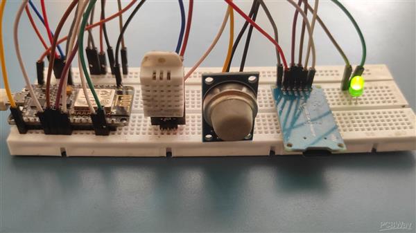
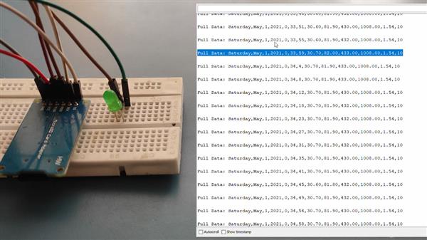
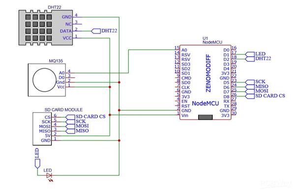
Nodemcu Data Logger
*PCBWay community is a sharing platform. We are not responsible for any design issues and parameter issues (board thickness, surface finish, etc.) you choose.
- Comments(0)
- Likes(0)
- 0 USER VOTES
- YOUR VOTE 0.00 0.00
- 1
- 2
- 3
- 4
- 5
- 6
- 7
- 8
- 9
- 10
- 1
- 2
- 3
- 4
- 5
- 6
- 7
- 8
- 9
- 10
- 1
- 2
- 3
- 4
- 5
- 6
- 7
- 8
- 9
- 10
- 1
- 2
- 3
- 4
- 5
- 6
- 7
- 8
- 9
- 10
 More by Sreeram.zeno
-
 Esp12-F Cluster V1.0
The ESP8266 is a low-cost Wi-Fi microchip, with built-in TCP/IP networking software, and microcontro...
-
 TB6612FNG Motor Driver
The TB6612FNG Motor Driver can control up to two DC motors at a constant current of 1.2A (3.2A peak)...
-
 Sunny Buddy Solar Charger v1.0
This is the Sunny Buddy, a maximum power point tracking (MPPT) solar charger for single-cell LiPo ba...
-
 Diy 74HC4051 8 Channel Mux Breakout Pcb
The 74HC4051; 74HCT4051 is a single-pole octal-throw analog switch (SP8T) suitable for use in analog...
-
 Diy RFM97CW Breakout Pcb
IntroductionLoRa? (standing for Long Range) is a LPWAN technology, characterized by a long range ass...
-
 ProMicro-RP2040 Pcb
The RP2040 is a 32-bit dual ARM Cortex-M0+ microcontroller integrated circuit by Raspberry Pi Founda...
-
 Serial Basic CH340G Pcb
A USB adapter is a type of protocol converter that is used for converting USB data signals to and fr...
-
 Mp3 Shield For Arduino
Hardware OverviewThe centerpiece of the MP3 Player Shield is a VS1053B Audio Codec IC. The VS1053B i...
-
 MRK CAN Shield Arduino
The CAN-BUS Shield provides your Arduino or Redboard with CAN-BUS capabilities and allows you to hac...
-
 AVR ISP Programmer
AVR is a family of microcontrollers developed since 1996 by Atmel, acquired by Microchip Technology ...
-
 Diy Arduino mega Pcb
The Arduino Mega 2560 is a microcontroller board based on the ATmega2560. It has 54 digital input/ou...
-
 Max3232 Breakout Board
MAX3232 IC is extensively used for serial communication in between Microcontroller and a computer fo...
-
 Line Follower Pcb
The Line Follower Array is a long board consisting of eight IR sensors that have been configured to ...
-
 HMC6343 Accelerometer Module
The HMC6343 is a solid-state compass module with tilt compensation from Honeywell. The HMC6343 has t...
-
 RTK2 GPS Module For Arduino
USBThe USB C connector makes it easy to connect the ZED-F9P to u-center for configuration and quick ...
-
 Arduino Explora Pcb
The Arduino Esplora is a microcontroller board derived from the Arduino Leonardo. The Esplora differ...
-
 Diy Stepper Motor Easy Driver
A motor controller is a device or group of devices that can coordinate in a predetermined manner the...
-
 Diy Arduino Pro Mini
The Arduino Pro Mini is a microcontroller board based on the ATmega168 . It has 14 digital input/out...
-
-
AEL-2011 Power Supply Module
525 0 2 -
AEL-2011 50W Power Amplifier
485 0 2 -
-
-
Custom Mechanical Keyboard
693 0 0 -
Tester for Touch Screen Digitizer without using microcontroller
330 2 2 -
Audio reactive glow LED wristband/bracelet with NFC / RFID-Tags
310 0 1 -
-
-


