8Ch P-Channel-Mosfet-Breakout
8-Ch P-Mos Breakout
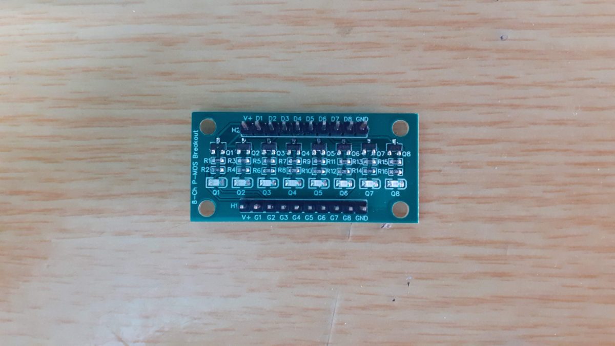
While prototyping our projects, we Makers often need to interface devices with a higher current draw, like motors, or RGB lights, to our microcontrollers. These typically are unsuitable for connecting directly to an Arduino, ESP32 or Raspberry Pi’s GPIO pins. This is usually the time when we start grabbing transistors or MOSFETs.
While I normally keep a few leaded transistors and MOSFETs in the lab, These are not always convenient to use, as they may be in big packages or have the wrong specifications for the task that we are trying to perform.
SMD versions are more common in my lab, but they come with the problem of being small, and also completely unfriendly to the breadboard environment.
I have thus been playing with an idea to make a series of dedicated breakout boards for just this purpose. Having an easy way to test a specific MOSFET for a design, having more than one of them handy, without all the wiring issues, and using the bare minimum of those DuPont wires!
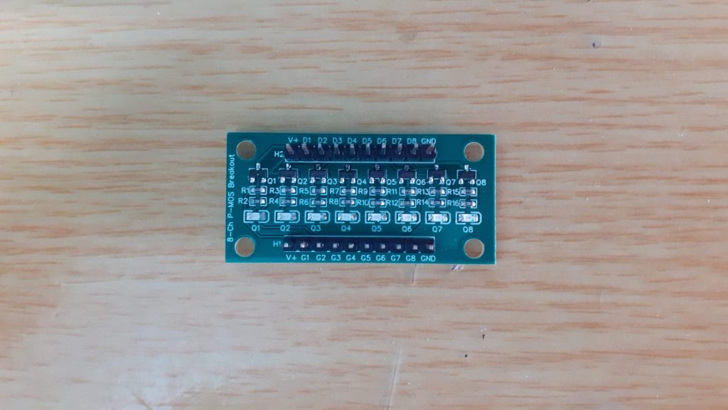
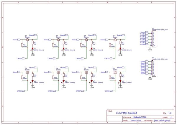
I came up with the following prototype, which, while not completely optimised yet, already makes things easier. The breakout board provides 8 P-Channel Mosfets, with a single source connection, and individually broken-out Drain and Gate pins.
LED indicators on each channel provide a visual indication of the status of each P-Mos device, and the breakout can also be mounted directly into an enclosure if needed.
What is on the PCB?
Each channel comprises a P-Channel Mosfet, in this case, a SI2301, which has a suitably low gate voltage, a pullup resistor on the gate, to keep it from floating, a status-indicating LED and a current-limiting resistor for the LED.
No gate resistor was added, as this would change depending on the actual MOSFET, as well as the microcontroller that you use. The Gate pullup resistor can also be left unpopulated, in case you need to do something specific there.
Two rows of 10-way, 2.54 header pins are at the top and bottom of the PCB, to make using the breakout on a breadboard possible.
The Pinouts are as follows
H2 – Top V+ D1 D2 D3 D4 D5 D6 D7 D8 GND
with Dx corresponding to the Drain pin of each MOSFET. All the Source pins are internally connected together, as I assumed that I will use the same source voltage on each channel anyway.
H1 – Bottom V+ G1 G2 G3 G4 G5 G6 G7 G8 GND
with Gx corresponding to the gate pin of each MOSFET.
V+ and GND for each header is internally connected, to make it possible to supply V+ and Gnd on any of the two headers.
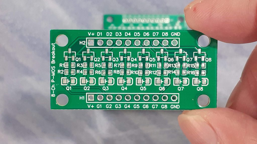 PCB Top Layer
Using the Breakout
Using the breakout is straightforward. Connect a source voltage to either of the V+ pins and Ground to either of the GND pins. ( the ground is used internally for the status LEDs)
Connect your load, with the positive to a drain pin, let us say D1, and the load ground to your breadboard, or power supply ground. Connect the corresponding gate pin, in our case G1, to the microcontroller pin of your choice, through a suitable gate resistor, and pull it high at setup, to ensure that the MOSFET stays off. Pull low to activate as needed.
Please note that you should not try to switch excessively large currents through a single MOSFET Channel, as the PCB traces can realistically only handle approximately 300 to 400mA per channel.
Note 2: If you are driving an inductive load, it is considered good practice to add a flywheel diode on the load as well. This will protect the MOSFET from back EMF when the MOSFET is switched off.
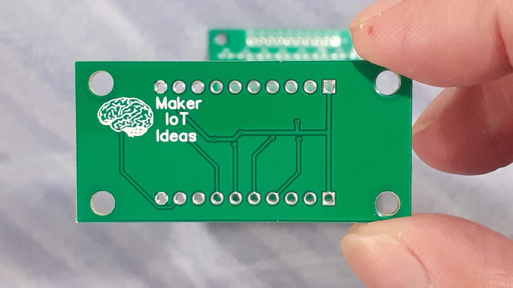 PCB Back
Example code for using the breakout (Arduino)
// Declare Gate driving GPIO pins
int gate1 = 10;
int gate2 = 11;
void setup() {
// Set the GPIO pins as outputs and drive them HIGH
// This keeps the channels switched "OFF"
digitalWrite(gate1,HIGH);
digitalWrite(gate2,HIGH);
pinMode(gate1,OUTPUT);
pinMode(gate2,OUTPUT);
// Writing to the GPIO's before setting their pin Mode,ensures that the
// GPIO's are in fact initiated in a know correct state.
Serial.begin(115200);
}
void loop() {
// In the loop, we just toggle the GPIOs, thus
// alternatively switching the channels on or off
digitalWrite(gate1,!digitalRead(gate1));
digitalWrite(gate2,!digitalRead(gate1));
delay(1000);
}
// Declare Gate driving GPIO pins int gate1 = 10; int gate2 = 11; void setup() { // Set the GPIO pins as outputs and drive them HIGH // This keeps the channels switched "OFF" digitalWrite(gate1,HIGH); digitalWrite(gate2,HIGH); pinMode(gate1,OUTPUT); pinMode(gate2,OUTPUT); // Writing to the GPIO's before setting their pin Mode,ensures that the // GPIO's are in fact initiated in a know correct state. Serial.begin(115200); } void loop() { // In the loop, we just toggle the GPIOs, thus // alternatively switching the channels on or off digitalWrite(gate1,!digitalRead(gate1)); digitalWrite(gate2,!digitalRead(gate1)); delay(1000); }
8Ch P-Channel-Mosfet-Breakout
*PCBWay community is a sharing platform. We are not responsible for any design issues and parameter issues (board thickness, surface finish, etc.) you choose.

Raspberry Pi 5 7 Inch Touch Screen IPS 1024x600 HD LCD HDMI-compatible Display for RPI 4B 3B+ OPI 5 AIDA64 PC Secondary Screen(Without Speaker)
BUY NOW
ESP32-S3 4.3inch Capacitive Touch Display Development Board, 800×480, 5-point Touch, 32-bit LX7 Dual-core Processor
BUY NOW
Raspberry Pi 5 7 Inch Touch Screen IPS 1024x600 HD LCD HDMI-compatible Display for RPI 4B 3B+ OPI 5 AIDA64 PC Secondary Screen(Without Speaker)
BUY NOW- Comments(0)
- Likes(0)
 Log in to post comments.
- 0 USER VOTES
- YOUR VOTE 0.00 0.00
- 1
- 2
- 3
- 4
- 5
- 6
- 7
- 8
- 9
- 10
- 1
- 2
- 3
- 4
- 5
- 6
- 7
- 8
- 9
- 10
- 1
- 2
- 3
- 4
- 5
- 6
- 7
- 8
- 9
- 10
- 1
- 2
- 3
- 4
- 5
- 6
- 7
- 8
- 9
- 10
 More by Jean Redelinghuys MakerIoT2020
-
 RA-02 Breakout with Level converters
Breadboard and beginner-friendly RA-02 Breakout ModuleMost Makers and electronics enthusiasts may al...
-
 ATMEGA328P Module with integrated LoRa and CAN Bus
ATMEGA328P Module with integrated LoRa and CAN-BUSINTRODUCTIONIn my quest to perfect my LoRa telemet...
-
 Sx127x-Ra-02-Test-Module with ATMEGA328P-AU
SX127x LoRa/FSK/OOK Prototype Radio BoardI recently had a requirement to do some automation/telemetr...
-
 USB-ASP Programmer ATMEGA8
Build your own USB-ASP Programmer CloneBymakeriot2020 FEB 21, 2022 Arduino, ASP programmerUsing mor...
-
 ATTiny1616-LIGHT-Controller-with-CAN_B_PCB_ATTiny1616-LIGHT-Controller-with-C_2024-09-11
Assembly of the ATTiny1616 Can bus controller PCBThe Assembly of the ATTiny1616 Can Bus Controller P...
-
 ATTiny1616QFN-CAN-Remote-Neopixel-Ligh_PCB_ATTiny1616QFN-CAN-Remote-Neopixel-2024-09-11_2024-09-11
NeoPixel CAN-Bus Module with local controlAs part of my current project to add NeoPixels to the cabi...
-
 PCB_MCP23008_2023-10-08
MCP23008 BreakoutI designed this breakout to assist me during prototyping my next version of the “RP...
-
 PCB_XiaoRP2040-Mouse-REV2
Xiao RP2040 Joystick Mouse – revision 2.00Revision 1.0 of the ProjectOver the last few months, I hav...
-
 Multi Purpose IO Card
Multi-Purpose IO CardWhen we are working on a prototype, we always need access to pushbuttons, encod...
-
 Variable Voltage Power Module
Powering electronics projects are always challenging. This Variable vol...
Variable Voltage Power Module
Variable Voltage Power ModulePowering electronics projects are always challenging. This Variable vol...
-
 I2C Matrix Keypad
An I2C Matrix KeypadThe completed I2C Matrix KeypadIn a previous post this month I introduced my 4×4...
-
 ESP32-S Development Board, in "Arduino Uno" form factor
UPDATE 24/06/2023:This board now has a Hardware Revision 2.0 available. It is the same board but wit...
-
 W307186ASC94_Gerber_PCB_USB-Ports
USB Power Supply ModuleUSB Ports are quite handy to power all our day-to-day electronic devices, but...
-
 Atmega 328P based PWM controller Card
ATMega 328P Based PWM controller CardAs part of my recent ESP-12E I2C Base Board project, I designed...
-
 W307186ASC71_Gerber_PCB_ESP-Now Remote
Today we will look at the remote control unit for the Robotic Toy Car – Part 6.The project is close ...
-
 W307186ASV69_Gerber_PCB_Robot-Car-MCU-Board Prototype
In our last project, we started working on repurposing an old toy car. In this part, Robot Toy Car –...
-
 W307186ASV62_Gerber_PCB_DUAL-H-Bridge
by makeriot2020 on May 27, 2022Many of us have old toys laying around the house, they belong to ou...
-
 CAN-BUS Breakout
Breadboard Compatible CAN-BUS Breakout ModuleWhat is this:Some of us have already used the commonly ...
-
 RA-02 Breakout with Level converters
Breadboard and beginner-friendly RA-02 Breakout ModuleMost Makers and electronics enthusiasts may al...
-
 ATMEGA328P Module with integrated LoRa and CAN Bus
ATMEGA328P Module with integrated LoRa and CAN-BUSINTRODUCTIONIn my quest to perfect my LoRa telemet...
-
 Sx127x-Ra-02-Test-Module with ATMEGA328P-AU
SX127x LoRa/FSK/OOK Prototype Radio BoardI recently had a requirement to do some automation/telemetr...
-
 USB-ASP Programmer ATMEGA8
Build your own USB-ASP Programmer CloneBymakeriot2020 FEB 21, 2022 Arduino, ASP programmerUsing mor...
-
 ATTiny1616-LIGHT-Controller-with-CAN_B_PCB_ATTiny1616-LIGHT-Controller-with-C_2024-09-11
Assembly of the ATTiny1616 Can bus controller PCBThe Assembly of the ATTiny1616 Can Bus Controller P...
-
 ATTiny1616QFN-CAN-Remote-Neopixel-Ligh_PCB_ATTiny1616QFN-CAN-Remote-Neopixel-2024-09-11_2024-09-11
NeoPixel CAN-Bus Module with local controlAs part of my current project to add NeoPixels to the cabi...
-
 PCB_MCP23008_2023-10-08
MCP23008 BreakoutI designed this breakout to assist me during prototyping my next version of the “RP...
-
 PCB_XiaoRP2040-Mouse-REV2
Xiao RP2040 Joystick Mouse – revision 2.00Revision 1.0 of the ProjectOver the last few months, I hav...
-
 Multi Purpose IO Card
Multi-Purpose IO CardWhen we are working on a prototype, we always need access to pushbuttons, encod...
-
 Variable Voltage Power Module
Powering electronics projects are always challenging. This Variable vol...
Variable Voltage Power Module
Variable Voltage Power ModulePowering electronics projects are always challenging. This Variable vol...
-
 I2C Matrix Keypad
An I2C Matrix KeypadThe completed I2C Matrix KeypadIn a previous post this month I introduced my 4×4...
-
 ESP32-S Development Board, in "Arduino Uno" form factor
UPDATE 24/06/2023:This board now has a Hardware Revision 2.0 available. It is the same board but wit...
-
-
Commodore 64 1541-II 1581 Floppy Disk Drive C64 Power Supply Unit USB-C 5V 12V DIN connector 5.25
393 1 3 -
-
-
-
-
-
-
-
Modifying a Hotplate to a Reflow Solder Station
1253 1 6 -
MPL3115A2 Barometric Pressure, Altitude, and Temperature Sensor
715 0 1 -


