


Breadboard Power Rail Bridge - Rev 2.0
Breadboard Power Rail Bridge
This is a sort of tongue-in-the-cheek project, that started with good intentions, and ended up wholly over-engineered and sort of “broken” due to adding “added features” like LEDs and an additional power header.
What was the initial intention?
[This is what I actually wanted to achieve]
My breadboards all have interrupted power rails, and it is thus always necessary to bridge them with jumper wires to have a continuous rail. This is needed because I very often have more than one project on a single breadboard, and do not want to have to use separate power modules for each. I also tend to test out some part of a circuit on a separate part of the breadboard, before incorporating it into the main circuit.
[ I completely overdesigned this, ending up with something completely different from what I wanted]
Wire jumpers are definitely the easier and fastest, but having been struck by a “what if I do this instead” moment, this tiny PCB was designed and subsequently sent to manufacturing…
So does it work?
Yes, it works, for its intended purpose of bridging the power rails, but that is where the wheels come off. Let me explain, trust me, it will be fun, and we can all laugh at it in the end…
Breadboard power rails are usually marked Red for positive, and Blue or Black for negative… Most people on this planet are also right-handed, and would thus place a power module on the right-hand side of a breadboard ( although some won’t..) Being left-handed myself, and still trying to please right-handed people, my power module will be “upside down” on the left-hand side of a breadboard… which is fine with me, as I remember to swap the colours of the rails in my mind, making red negative and blue positive… not a big issue is you always do it that way…
So what went wrong…
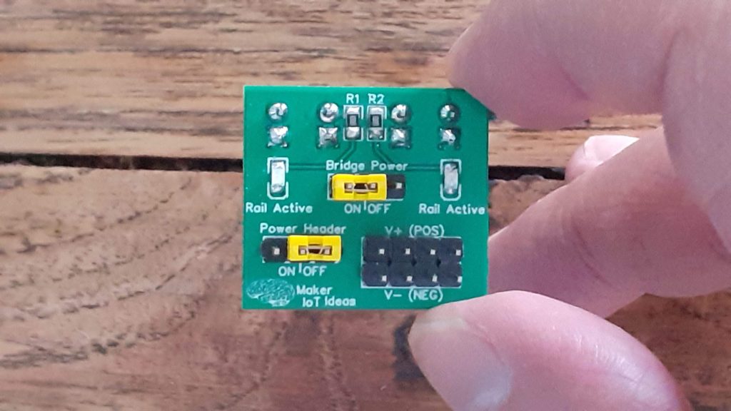
While designing this, I initially planned on a simple PCB bridge, with a jumper on the positive line, acting as a switch, and a continuous ground that is always connected.. all fine, problem number 1 being that I looked at the colours of the power rails while designing it, measuring the gaps etc to get the spacing just right…
Problem number 2 is that the top and bottom rails are in the same configuration, Red at the top, blue at the bottom… and thus plugging in a bridge into either should be ok… and it really should have been, if I did not decide to add a status LED on each side of the bridge, and an additional power header… because turns out that I forgot that the bridge at the top will in effect be “mirrored” when plugged in ( and thus having components that are reversed polarity) – mirrored, due to the fact that you now have to plug the top rail bridge upside down into the breadboard, because it will otherwise interfere with the prototyping space
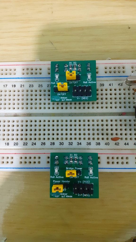
[This was the direct effect of my lack of attention to detail – and yes, it works perfectly in this configuration – if we ignore the wasted space on the top half of the board]
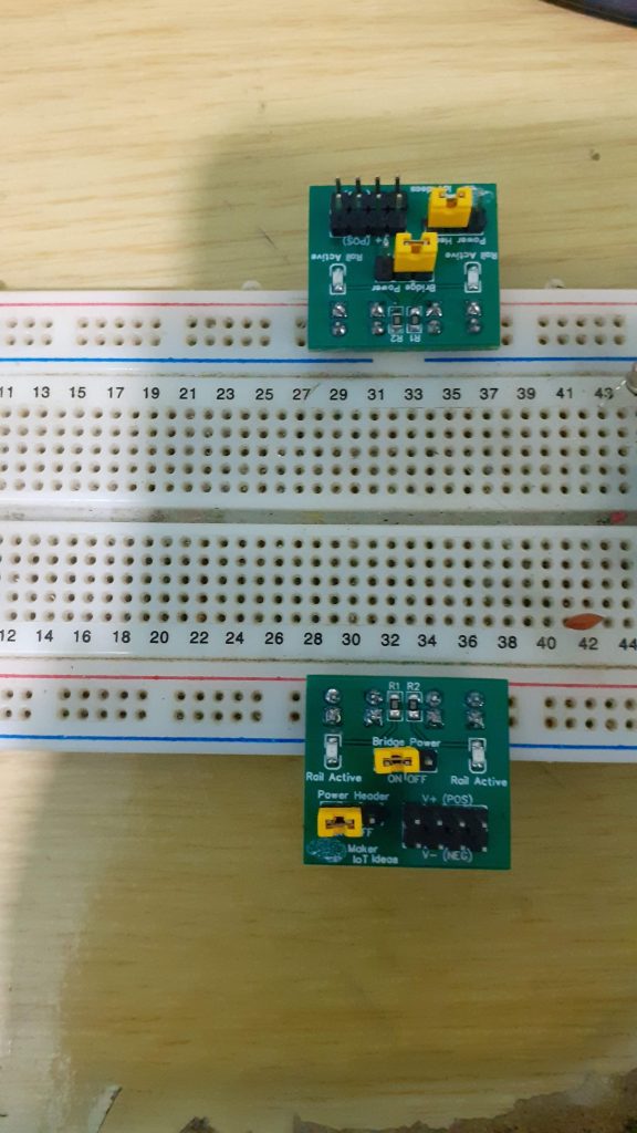
[This is the practical reality – one bridge must be installed ‘upside-down’]
Lesson learned; I can be quite scatterbrained at times, especially when juggling a few projects and customers at the same time ( I am only human anyway ). Thus this project, although it looks nice, and can be useful, needs to go back to the drawing board for a complete redesign, without all those “added features”
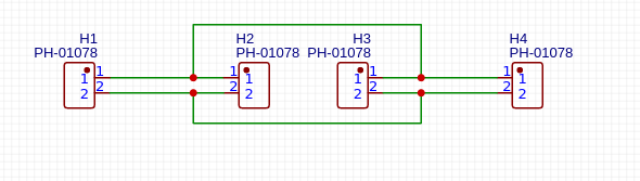
The Schematic
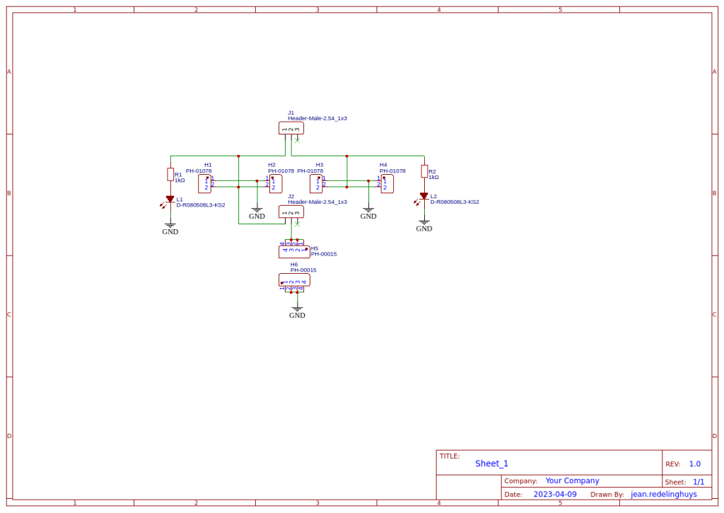
The schematic is straightforward, with no surprises. Two LEDs ( polarity sensitive ) and then those headers and jumpers, which also need up being polarity sensitive – in a manner of speaking
Quite different from what I originally wanted to do
Conclusion
This project served many purposes beyond the actual use of the PCB that was designed. In a way, I am quite happy that I screwed up so badly on this one – here is the reason why:
Because I do quite a lot of PCB design each month, for customers or personal projects, I often tend to get a bit over-confident, and also rush things through,
while believing that I will catch every mistake before I send something off to production. Normally, I am quite good at that, and my error rate is actually quite low… But, This month, being quite busier than usual, and having had a fair amount of distractions, served as the perfect lesson to drag me down a notch or two, and remind me that I have to be way more attentive, especially when things are going hectic, and there are a few projects to juggle around at the same time.
The second reason why it is a good thing when the wheels come off like this, once in a while, is that it serves as a perfect example of what your PCB manufacturer’s actual job is. So, this is especially for the new guys that may not know this: Your PCB Manufacturer has only one job – To manufacture your PCB EXACTLY AS YOU DESIGNED IT – Scary, right? Sure, they will let you know if your design falls outside of their tolerances of capabilities. They will let you know if your board fails a flying probe test if you have that kind of arrangement with them… But it is NEVER their job to correct or attempt to change any of your design files.
So, what is the moral of the story, regarding both of the points that I made above?
If you screw up on the design, it is your, and only your fault. Nobody else is to blame, ever. The buck stops with you, the designer.
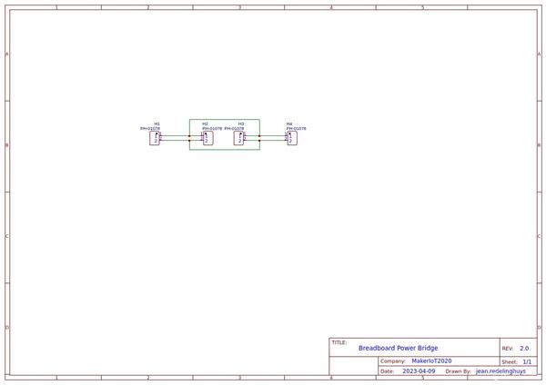
Breadboard Power Rail Bridge - Rev 2.0
*PCBWay community is a sharing platform. We are not responsible for any design issues and parameter issues (board thickness, surface finish, etc.) you choose.


- Comments(0)
- Likes(0)
More by Jean Redelinghuys MakerIoT2020
-
 PCB_MCP23008_2023-10-08
MCP23008 BreakoutI designed this breakout to assist me during prototyping my next version of the “RP...
PCB_MCP23008_2023-10-08
MCP23008 BreakoutI designed this breakout to assist me during prototyping my next version of the “RP...
-
 PCB_XiaoRP2040-Mouse-REV2
Xiao RP2040 Joystick Mouse – revision 2.00Revision 1.0 of the ProjectOver the last few months, I hav...
PCB_XiaoRP2040-Mouse-REV2
Xiao RP2040 Joystick Mouse – revision 2.00Revision 1.0 of the ProjectOver the last few months, I hav...
-
 Multi Purpose IO Card
Multi-Purpose IO CardWhen we are working on a prototype, we always need access to pushbuttons, encod...
Multi Purpose IO Card
Multi-Purpose IO CardWhen we are working on a prototype, we always need access to pushbuttons, encod...
-
 Variable Voltage Power Module
Powering electronics projects are always challenging. This Variable vol...
Variable Voltage Power Module
Variable Voltage Power ModulePowering electronics projects are always challenging. This Variable vol...
-
 I2C Matrix Keypad
An I2C Matrix KeypadThe completed I2C Matrix KeypadIn a previous post this month I introduced my 4×4...
I2C Matrix Keypad
An I2C Matrix KeypadThe completed I2C Matrix KeypadIn a previous post this month I introduced my 4×4...
-
 ESP32-S Development Board, in "Arduino Uno" form factor
UPDATE 24/06/2023:This board now has a Hardware Revision 2.0 available. It is the same board but wit...
ESP32-S Development Board, in "Arduino Uno" form factor
UPDATE 24/06/2023:This board now has a Hardware Revision 2.0 available. It is the same board but wit...
-
 W307186ASC94_Gerber_PCB_USB-Ports
USB Power Supply ModuleUSB Ports are quite handy to power all our day-to-day electronic devices, but...
W307186ASC94_Gerber_PCB_USB-Ports
USB Power Supply ModuleUSB Ports are quite handy to power all our day-to-day electronic devices, but...
-
 Atmega 328P based PWM controller Card
ATMega 328P Based PWM controller CardAs part of my recent ESP-12E I2C Base Board project, I designed...
Atmega 328P based PWM controller Card
ATMega 328P Based PWM controller CardAs part of my recent ESP-12E I2C Base Board project, I designed...
-
 W307186ASC71_Gerber_PCB_ESP-Now Remote
Today we will look at the remote control unit for the Robotic Toy Car – Part 6.The project is close ...
W307186ASC71_Gerber_PCB_ESP-Now Remote
Today we will look at the remote control unit for the Robotic Toy Car – Part 6.The project is close ...
-
 W307186ASV69_Gerber_PCB_Robot-Car-MCU-Board Prototype
In our last project, we started working on repurposing an old toy car. In this part, Robot Toy Car –...
W307186ASV69_Gerber_PCB_Robot-Car-MCU-Board Prototype
In our last project, we started working on repurposing an old toy car. In this part, Robot Toy Car –...
-
 W307186ASV62_Gerber_PCB_DUAL-H-Bridge
by makeriot2020 on May 27, 2022Many of us have old toys laying around the house, they belong to ou...
W307186ASV62_Gerber_PCB_DUAL-H-Bridge
by makeriot2020 on May 27, 2022Many of us have old toys laying around the house, they belong to ou...
-
 CAN-BUS Breakout
Breadboard Compatible CAN-BUS Breakout ModuleWhat is this:Some of us have already used the commonly ...
CAN-BUS Breakout
Breadboard Compatible CAN-BUS Breakout ModuleWhat is this:Some of us have already used the commonly ...
-
 RA-02 Breakout with Level converters
Breadboard and beginner-friendly RA-02 Breakout ModuleMost Makers and electronics enthusiasts may al...
RA-02 Breakout with Level converters
Breadboard and beginner-friendly RA-02 Breakout ModuleMost Makers and electronics enthusiasts may al...
-
 ATMEGA328P Module with integrated LoRa and CAN Bus
ATMEGA328P Module with integrated LoRa and CAN-BUSINTRODUCTIONIn my quest to perfect my LoRa telemet...
ATMEGA328P Module with integrated LoRa and CAN Bus
ATMEGA328P Module with integrated LoRa and CAN-BUSINTRODUCTIONIn my quest to perfect my LoRa telemet...
-
 Sx127x-Ra-02-Test-Module with ATMEGA328P-AU
SX127x LoRa/FSK/OOK Prototype Radio BoardI recently had a requirement to do some automation/telemetr...
Sx127x-Ra-02-Test-Module with ATMEGA328P-AU
SX127x LoRa/FSK/OOK Prototype Radio BoardI recently had a requirement to do some automation/telemetr...
-
 USB-ASP Programmer ATMEGA8
Build your own USB-ASP Programmer CloneBymakeriot2020 FEB 21, 2022 Arduino, ASP programmerUsing mor...
USB-ASP Programmer ATMEGA8
Build your own USB-ASP Programmer CloneBymakeriot2020 FEB 21, 2022 Arduino, ASP programmerUsing mor...
-
 ATTiny1616-LIGHT-Controller-with-CAN_B_PCB_ATTiny1616-LIGHT-Controller-with-C_2024-09-11
Assembly of the ATTiny1616 Can bus controller PCBThe Assembly of the ATTiny1616 Can Bus Controller P...
ATTiny1616-LIGHT-Controller-with-CAN_B_PCB_ATTiny1616-LIGHT-Controller-with-C_2024-09-11
Assembly of the ATTiny1616 Can bus controller PCBThe Assembly of the ATTiny1616 Can Bus Controller P...
-
 ATTiny1616QFN-CAN-Remote-Neopixel-Ligh_PCB_ATTiny1616QFN-CAN-Remote-Neopixel-2024-09-11_2024-09-11
NeoPixel CAN-Bus Module with local controlAs part of my current project to add NeoPixels to the cabi...
ATTiny1616QFN-CAN-Remote-Neopixel-Ligh_PCB_ATTiny1616QFN-CAN-Remote-Neopixel-2024-09-11_2024-09-11
NeoPixel CAN-Bus Module with local controlAs part of my current project to add NeoPixels to the cabi...
-
-
mammoth-3D SLM Voron Toolhead – Manual Drill & Tap Edition
153 0 0 -
-
-
-
Tester for Touch Screen Digitizer without using microcontroller
403 2 2 -
Audio reactive glow LED wristband/bracelet with NFC / RFID-Tags
366 0 1 -
-


