
|
A000066Arduino
|
x 1 | |

|
servomotor |
x 1 |

|
arduino IDEArduino
|
|
|
|
Processing |
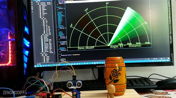
Diy Arduino Radar Project
Environment (IDE)
The Processing Environment includes a text editor, a compiler, and a display window. It enables the creation of software within a carefully designed set of constraints.
Overview
The Processing Development Environment (PDE) makes it easy to write Processing programs. Programs are written in the Text Editor and started by pressing the Run button. In Processing, a computer program is called a sketch. Sketches are stored in the Sketchbook, which is a folder on your computer.
Sketches can draw two- and three-dimensional graphics. The default renderer is for drawing two-dimensional graphics. The P3D renderer makes it possible to draw three-dimensional graphics, which includes controlling the camera, lighting, and materials. The P2D renderer is a fast, but less accurate renderer for drawing two-dimensional graphics. Both the P2D and P3D renderers are accelerated if your computer has an OpenGL compatible graphics card.
The capabilities of Processing are extended with Libraries and Tools. Libraries make it possible for sketches to do things beyond the core Processing code. There are hundreds of libraries contributed by the Processing community that can be added to your sketches to enable new things like playing sounds, doing computer vision, and working with advanced 3D geometry. Tools extend the PDE to help make creating sketches easier by providing interfaces for tasks like selecting colors.
Processing has different programming modes to make it possible to deploy sketches on different platforms and program in different ways. The Java mode is the default. Other programming modes may be downloaded by selecting "Add Mode..." from the menu in the upper-right corner of the PDE.
Processing Development Environment (PDE)
The Processing Development Environment (PDE) consists of a simple text editor for writing code, a message area, a text console, tabs for managing files, a toolbar with buttons for common actions, and a series of menus. The menus options change from mode to mode. The default Java mode is documented here.

Programs written using Processing are called sketches. These sketches are written in the text editor. It has features for cutting/pasting and for searching/replacing text. The message area gives feedback while saving and exporting and also displays errors. The console displays text output by Processing sketches including complete error messages and text output from sketches with the print() and println() functions. (Note that the console works well for occasional messages, but is not intended for high-speed, real-time output.)
The buttons on the toolbar can run and stop programs,

Run
Runs the sketch. In Java mode, it compiles the code and opens a new display window.

Stop
Terminates a running sketch.
Adds the necessary import statements to the top of the current sketch. For example, selecting Sketch ? Import Library ? pdf adds the statement "import processing.pdf.\*;" to the top of the file. These import statements are necessary for using Libraries.
Converts fonts into the Processing font format (VLW) and adds to the current sketch. Opens a dialog box that gives options for setting the font, its size, if it is anti-aliased (smooth), and which characters to be generated. The amount of memory required for the font is determined by the size selected and the number of characters selected through the "Characters..." menu; Processing fonts are textures, so larger fonts require more image data. Fonts can also be created in the code with the createFont() function.
All Processing projects are called sketches. Each sketch has its own folder. The main file for each sketch has the same name as the folder and is found inside. For example, if the sketch is named "Sketch_123", the folder for the sketch will be called "Sketch_123" and the main file will be called "Sketch_123.pde". The PDE file extension is an acronym for the Processing Development Environment
Processing sketches can be stored anywhere on your computer, but by default they are stored in the sketchbook, which will be in different places on your computer or network depending if you use PC, Mac, or Linux and how the preferences are set. To locate this folder, select the "Preferences" option from the File menu (or from the "Processing" menu on the Mac) and look for the"Sketchbook location."
A sketch folder sometimes contains other folders for media files and other code. When a font or image is added to a sketch by selecting "Add File..." from the Sketch menu, a "data" folder is created. Files may also be added to your Processing sketch by dragging them into the text editor. Image and sound files dragged into the application window will automatically be added to the current sketch's "data" folder. All images, fonts, sounds, and other data files loaded in the sketch must be in this folder.
Renderers
Processing has three built-in screen renderers. The default renderer is for drawing two-dimensional shapes. P2D is a faster, but less accurate renderer for drawing two-dimensional shapes. P3D is for three-dimensional geometry; it can also control the camera, lighting, and materials. The P2D and P3D renderers are accelerated if your computer has an OpenGL compatible graphics card. The smooth() function affects the amount of antialiasing for each renderer. Check the reference for smooth() for more information.
The renderer used for each sketch is specified through the size() function.
Processing uses a coordinate system with the origin in the upper-left corner. If your sketch is 320 pixels wide and 240 pixels high, coordinate (0, 0) is the upper-left pixel and coordinate (320, 240) is in the lower-right. The last visible pixel in the lower-right corner of the screen is at position(319, 239) because pixels are drawn to the right and below the coordinate.
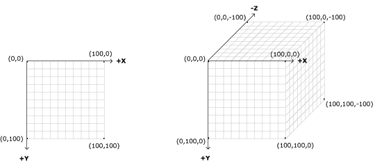
Using the three-dimension coordinate system of P3D, the z-coordinate is zero at the surface of the image, with negative z-values moving back in space. When drawing in 3D, the camera is positioned in the center of the screen.
Tabs, Multiple Files, and Classes
It can be inconvenient to write a long program within a single file. When Processing sketches grow to hundreds or thousands of lines, breaking them into modular units helps manage the different parts. Processing manages files with the Sketchbook and each sketch can have multiple files that are managed with tabs.
The arrow button to the right of the tabs in the Processing Development Environment is used to manage these files. Click this button to reveal options to create a new tab, rename the current tab, and delete the current tab. Tabs are intended for more advanced users, and for this reason, the menu that controls the tabs is intentionally made less prominent.
Advanced
When a program with multiple tabs is run, the code is grouped together and the classes in other tabs become inner classes. Because they're inner classes, they cannot have static variables. Simply place the "static" variable outside the class itself to do the same thing (it need not be explicitly named "static" once you list it in this manner). If you don't want code to be an inner class, you can also create a tab with a ".java" suffix, which means it will be interpreted as straight java code. It is also not possible to use static classes in separate tabs. If you do this, however, you'll need to pass the PApplet object to that object in that tab in order to get PApplet functions like line(), loadStrings() or saveFrame() to work.
Hardware:
Lets start the connections
connections with arduino uno
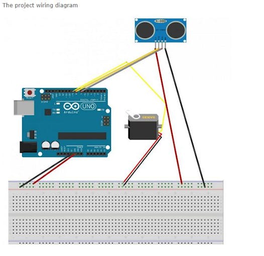
connect vcc of servomotor(red wire) and vcc of ultrasonic sensor to 5v of arduino
connect the gnd of ultrasonic sensor and servo(black wire) to ground of the arduino
connect trig and echo pin of ultrasonic sensor to 8 and 7 of arduino.
connect signal pin of servo to pin 9 of arduino.
connection with arduino nano for nano users
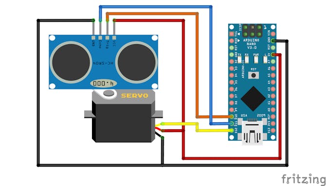
connect vcc of servomotor(red wire) and vcc of ultrasonic sensor to 5v of arduino
connect the gnd of ultrasonic sensor and servo(black wire) to ground of the arduino
connect trig and echo pin of ultrasonic sensor to D10 and D11 of arduino nano.
connect signal pin of servo to pin D12 of arduino nano.
In the code just change pins to D10, D11, D12.
Software:
Lets start first by installing arduino ide clickhere
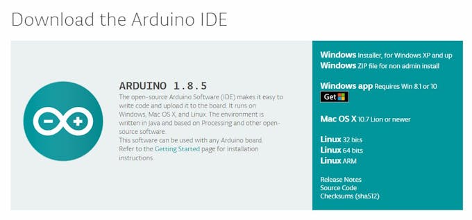
After downloading it paste the given code in it
Next download the latest version of processing ide
Paste the given code in processing ide
Run the processing ide.
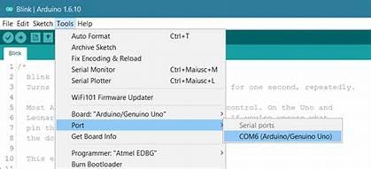
note: change the com3 on the code to your com port to which arduino ide is connected.
To know which com port you are connected follow the image.
Diy Arduino Radar Project
- Comments(0)
- Likes(6)
-
 Engineer
Oct 01,2024
-
 Lionstar55
Nov 24,2023
-
 Sebastian Mackowiak
Mar 21,2023
-
 SinTech
Dec 26,2022
-
 Engineer
Aug 25,2022
-
 Enrique Diaz
Jun 01,2022
- 0 USER VOTES
- YOUR VOTE 0.00 0.00
- 1
- 2
- 3
- 4
- 5
- 6
- 7
- 8
- 9
- 10
- 1
- 2
- 3
- 4
- 5
- 6
- 7
- 8
- 9
- 10
- 1
- 2
- 3
- 4
- 5
- 6
- 7
- 8
- 9
- 10
- 1
- 2
- 3
- 4
- 5
- 6
- 7
- 8
- 9
- 10
 More by Sreeram.zeno
-
 Esp12-F Cluster V1.0
The ESP8266 is a low-cost Wi-Fi microchip, with built-in TCP/IP networking software, and microcontro...
-
 TB6612FNG Motor Driver
The TB6612FNG Motor Driver can control up to two DC motors at a constant current of 1.2A (3.2A peak)...
-
 Sunny Buddy Solar Charger v1.0
This is the Sunny Buddy, a maximum power point tracking (MPPT) solar charger for single-cell LiPo ba...
-
 Diy 74HC4051 8 Channel Mux Breakout Pcb
The 74HC4051; 74HCT4051 is a single-pole octal-throw analog switch (SP8T) suitable for use in analog...
-
 Diy RFM97CW Breakout Pcb
IntroductionLoRa? (standing for Long Range) is a LPWAN technology, characterized by a long range ass...
-
 ProMicro-RP2040 Pcb
The RP2040 is a 32-bit dual ARM Cortex-M0+ microcontroller integrated circuit by Raspberry Pi Founda...
-
 Serial Basic CH340G Pcb
A USB adapter is a type of protocol converter that is used for converting USB data signals to and fr...
-
 Mp3 Shield For Arduino
Hardware OverviewThe centerpiece of the MP3 Player Shield is a VS1053B Audio Codec IC. The VS1053B i...
-
 MRK CAN Shield Arduino
The CAN-BUS Shield provides your Arduino or Redboard with CAN-BUS capabilities and allows you to hac...
-
 AVR ISP Programmer
AVR is a family of microcontrollers developed since 1996 by Atmel, acquired by Microchip Technology ...
-
 Diy Arduino mega Pcb
The Arduino Mega 2560 is a microcontroller board based on the ATmega2560. It has 54 digital input/ou...
-
 Max3232 Breakout Board
MAX3232 IC is extensively used for serial communication in between Microcontroller and a computer fo...
-
 Line Follower Pcb
The Line Follower Array is a long board consisting of eight IR sensors that have been configured to ...
-
 HMC6343 Accelerometer Module
The HMC6343 is a solid-state compass module with tilt compensation from Honeywell. The HMC6343 has t...
-
 RTK2 GPS Module For Arduino
USBThe USB C connector makes it easy to connect the ZED-F9P to u-center for configuration and quick ...
-
 Arduino Explora Pcb
The Arduino Esplora is a microcontroller board derived from the Arduino Leonardo. The Esplora differ...
-
 Diy Stepper Motor Easy Driver
A motor controller is a device or group of devices that can coordinate in a predetermined manner the...
-
 Diy Arduino Pro Mini
The Arduino Pro Mini is a microcontroller board based on the ATmega168 . It has 14 digital input/out...
-
-
AEL-2011 Power Supply Module
524 0 2 -
AEL-2011 50W Power Amplifier
485 0 2 -
-
-
Custom Mechanical Keyboard
693 0 0 -
Tester for Touch Screen Digitizer without using microcontroller
329 2 2 -
Audio reactive glow LED wristband/bracelet with NFC / RFID-Tags
310 0 1 -
-
-


