
|
arduino IDEArduino
|
Diy I2C Lcd Module
I2C_LCD is an easy-to-use display module, It can make display easier. Using it can reduce the difficulty of make, so that makers can focus on the core of the work.
We developed the Arduino library for I2C_LCD, user just need a few lines of the code can achieve complex graphics and text display features. It can replace the serial monitor of Arduino in some place, you can get running informations without a computer.
More than that, we also develop the dedicated picture data convert software (bitmap converter)now is available to support PC platform of windows, Linux, Mac OS. Through the bitmap convert software you can get your favorite picture displayed on I2C_LCD, without the need for complex programming.
Features
Only 2 Arduino pins are occupied (Use I2C interface).
Supports standard I2C mode (100Kbit/s) and fast I2C mode (400Kbit/s).
Compatible with multiple communication logic levels: 2.8~5VDC.
Arduino library supported, use a line of code to complete the display.
Integrate 7 sizes of ASCll fonts, 5 graphics functions.
Provide dedicated picture data convert software (Bitmap Converter).
Most of the complex operation is processed by I2C_LCD independent controller, saving user controller resources.
Supports cursor function, can set up 16 cursor flicker frequency.
Supports 128 level backlight lightness adjustment.
Support 64 level screen contrast adjustment.
Support device address modification.
Supports 127 I2C_LCD work in parallel.
When debugging code, it can take the place of the serial monitor to monitor the program running state.
Two abnormal recovery methods are provided: reset and restore the factory settings.
Compatible with Grove interface and 4Pin-100mil interface (under the Grove socket).
4 symmetrical fixed hole design for easy user installation.
China style unique appearance.
Platforms Supported
Interface Function
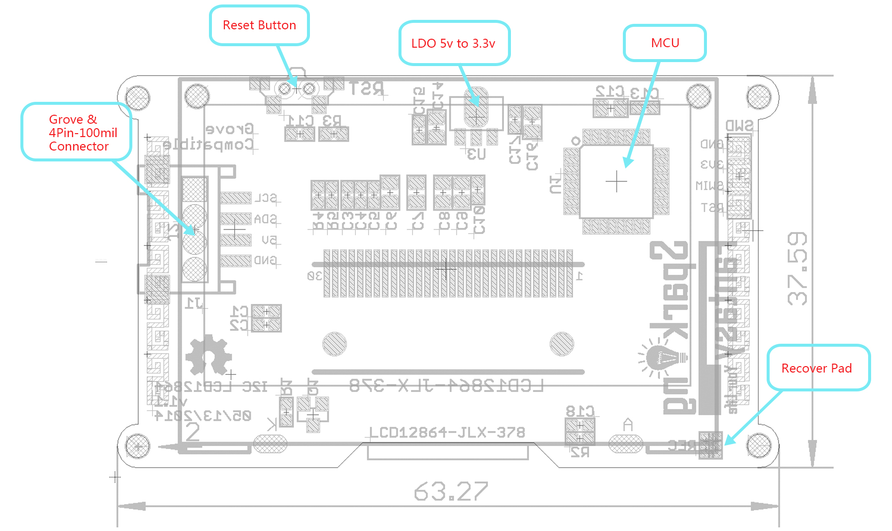
Getting Started
Step 1: Install the latest version of Arduino IDE to your computer.

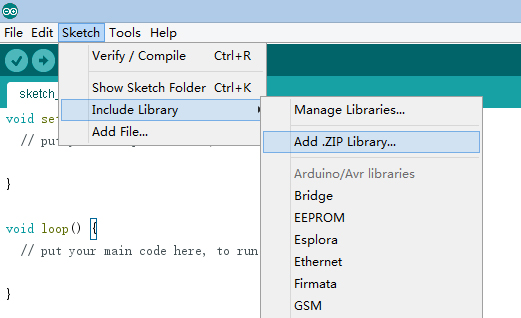
Step 2: Download and install the I2C_LCD library to Arduino IDE:
Open Arduino IDE, click Sketch -> Include library -> Add .ZIP library.
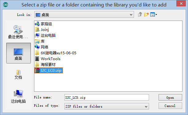
Find and select the I2C_LCD.zip file you just downloaded.
Restart the Arduino IDE.
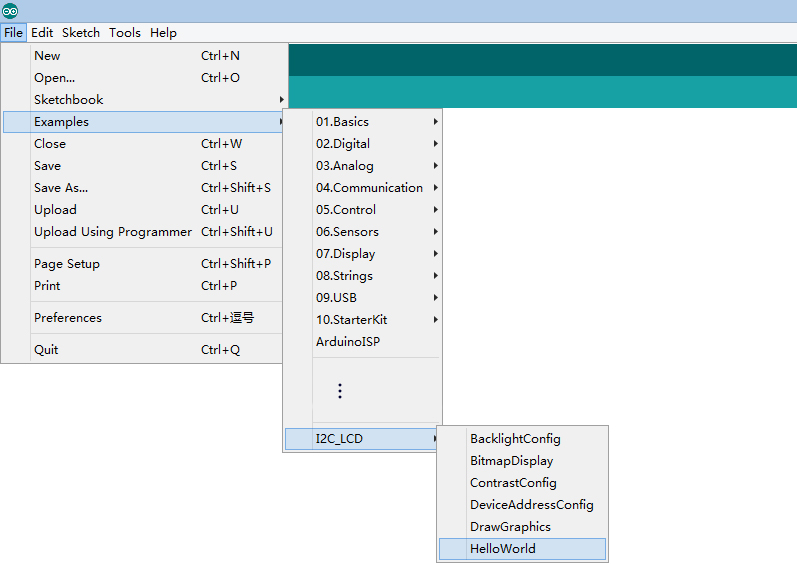
Step 3: Chose the example project which you like. (Take "HelloWorld" project for example here.)
Click File > Examples > I2C_LCD > HelloWorld
Step 4: Connect I2C_LCD to your Seeeduino Vx board with Grove cable. Then connect Seeeduino Vx board to your computer.
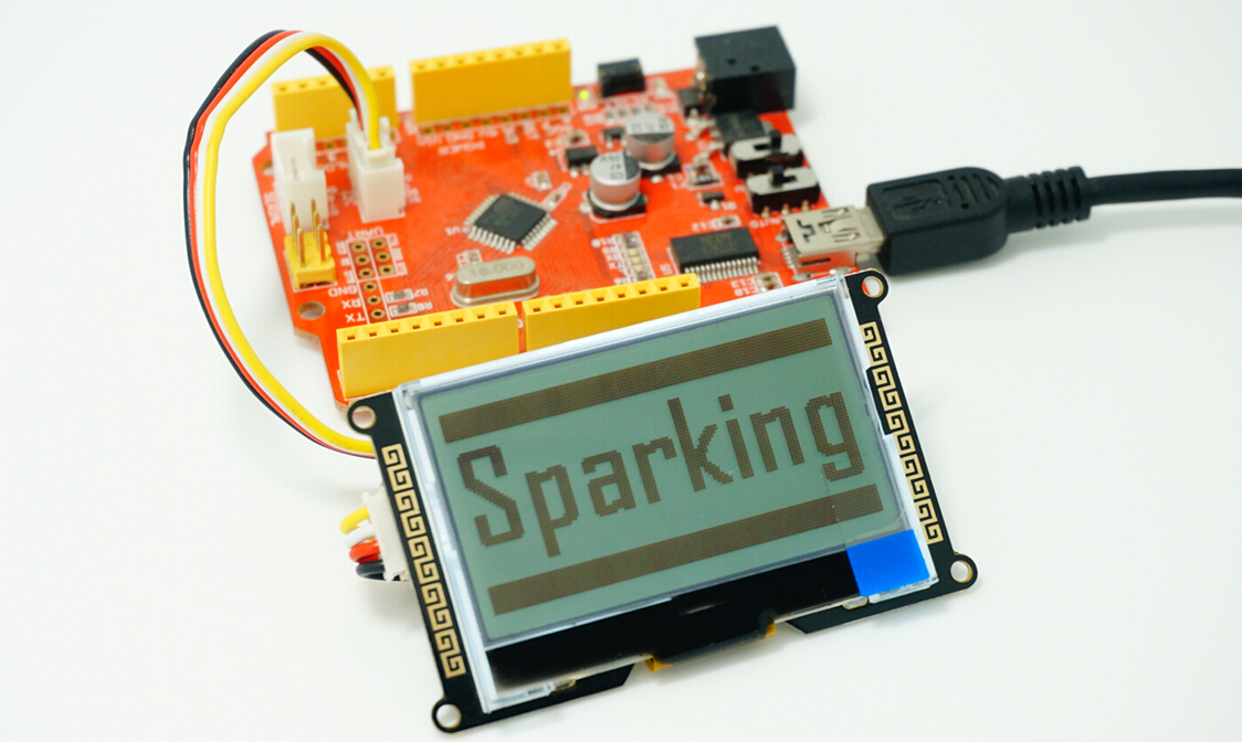
Step 5: Select your board and serial port.
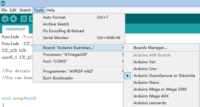
Select the board: Click Tools > Board > "Arduino Duemilanove or Diecimila"(Seeeduino V3.0 Or early version), "Arduino Uno"(Seeeduino Lotus or Seeeduino V4.0).
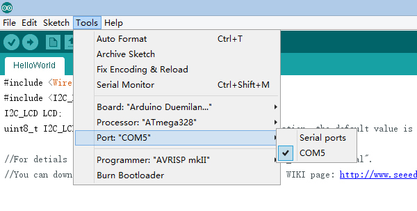
Select the COM: Click Tools -> Serial Port -> COMX(which connected with your board.)
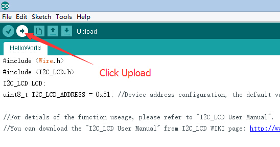
Step 6: Upload the program and enjoy yourself!
I2C_LCD is an easy-to-use display module, It can make display easier. Using it can reduce the difficulty of make, so that makers can focus on the core of the work. We developed the Arduino library for I2C_LCD, user just need a few lines of the code can achieve complex graphics and text display features.
I2C LCD Hardware Overview
A typical I2C LCD display consists of a HD44780 based character LCD display and an I2C LCD adapter. Let’s get to know them one by one.
Character LCD Display
True to its name, these LCDs are ideal for displaying text/characters only. A 16×2 character LCD, for example, has an LED backlight and can display 32 ASCII characters in two rows with 16 characters on each row.
Why I2C (IIC) Type LCD?
If you plan to add a simple readable interface in your next project. alphanumeric LCD may be the most preferred one due to various factors such as low cost, easily programmable, having no limitation of displaying special & even custom characters.
But to use it directly with a microcontroller, you would need atleast 6 pins – RS, EN, D7, D6, D5, and D4 (with R/W pin permanently grounded for write operation). When you are engaged in a complex project bundled with large number of modules, you may face pin shortage for your microcontroller. In such situations, I2C LCD comes handy making use of only 2 pins (SDA & SCL) to talk to MCU, thereby saving atleast 4 pins. If you already have I2C devices, this LCD module actually uses no more pins at all.

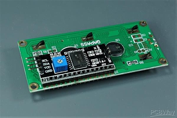
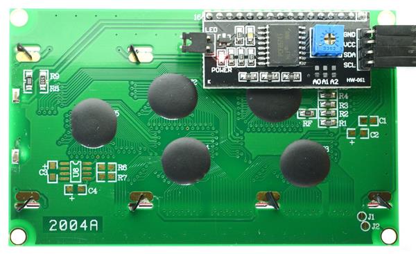
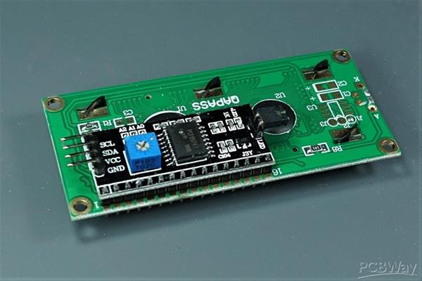
Before moving further, lets see how an LCD can be controlled by I2C. In the image shown above, you can see a backpack module fitted to the back of the LCD. He does the work using an I/O expander PCF8574, that communicates with the micro-controller by I2C.
Remote 8-bit I/O expander PCF8574
The PCF8574 provides general purpose remote I/O expansion for most microcontroller families via the two-line bidirectional bus (I2C-bus). The device consists of an 8-bit quasi-bidirectional port and an I2C-bus interface.

A quasi-bidirectional I/O can be used as an input or output without the use of a control signal for data direction. The PCF8574 has a low current consumption and includes latched outputs with high current drive capability. It also possesses an interrupt line (INT) which can be connected to the interrupt logic of the microcontroller. By sending an interrupt signal on this line, the remote I/O can inform the microcontroller if there is incoming data on its ports without having to communicate via the I2C-bus. This means that the PCF8574 can remain a simple slave device.

I2C LCD Backpack
You can use this with LCD modules that have a HD44780-compatible interface with various screen sizes. The key is that your LCD must have the interface pads in a single row of sixteen, so it matches the pins on the backpack.

As shown in the above image, the backpack has 4 pins namely GND, Vcc, SDA and SCL.
Besides, the backpack has the following key features
LED jumper should be in position to turn on the back-light.

The blue potentiometer on the backpack bord adjusts contrast. Adjust it to a position where the characters are bright and the background does not have boxes behind the characters.

The three hardware address pins A0, A1 and A2 allow eight devices to be on the same I2C-bus. You can change the address of the device according to the status of each of these pins. The default address of the device is 0X3F (with PCF8574AT).

Note that backpack modules centered around PCF8574/PCF8574T (SO16 package of PCF8574 in DIP16 package) have a default slave address of 0×27. For those with PCF8574A/PCF8574AT chip, the default slave address will change to 0x3F.

Once all the necessary connections are made, you can communicate with LCD using I2C.
Interfacing with Arduino
On Arduino UNO board, SDA (data line) is on analog pin 4, and SCL (clock line) is on analog pin 5. On the newer Arduino UNO (“R3″ layout), the SCL and SDA pins are available as separate pins. If you are using a different board, ensure that you connect the SDA and SCL pins. Power the board with 5V. The interfacing diagram is shown below.
You can get library from here. Add the library to your Arduino folder. We used the library NewliquidCrystal_1.3.4
Note: If you are using an Arduino board that works in 3.3V level, you need to use a level converter to communicate with the backpack.

Sample code for 16×2 LCD is given below. Upload the sketch to your Arduino board and you can see the LCD working. For 20×4 LCD, use the commented setup and comment the current setup.
/* Sample Code for 16x2 / 20x4 character I2C LCD
Upon powering, the given strings get displayed on the LCD. Then you can open the
Serial monitor and type in any characters to display */
#include <Wire.h> // Comes with Arduino IDE
#include <LiquidCrystal_I2C.h>
// Initialize the object with interfacing pins
LiquidCrystal_I2C lcd(0x3F, 2, 1, 0, 4, 5, 6, 7, 3, POSITIVE);
void setup()
{
Serial.begin(9600); // Initialize serial communication at 9600 baudrate
lcd.begin(16,2); // Initialize 20X4 LCD and turn on backlight
lcd.backlight();
lcd.setCursor(0,0); // Set cursor to column 1, line 1
lcd.write(" 16x2 character ");
lcd.setCursor(0,1); // Set cursor to column 1, line 2
lcd.write(" I2C LCD ");
delay(2000); // Display for sometime
lcd.noBacklight(); // Turn off backlight
delay(2000); // Turn on backlight again after sometime
lcd.backlight();
lcd.clear(); // Clear the display
lcd.setCursor(0,0);
lcd.write("Use Serial Mon");
lcd.setCursor(0,1);
lcd.write("Type to display");
}
/* Use this setup for 20x4 character LCD
void setup() // Setup - Runs once
{
Serial.begin(9600); // Initialize serial communication at 9600 baudrate
lcd.begin(20,4); // Initialize 20X4 LCD and turn on backlight
lcd.backlight();
lcd.setCursor(0,0); // Set cursor to column 1, line 1
lcd.write(" 20x4 character ");
lcd.setCursor(0,1); // Set cursor to column 1, line 2
lcd.write(" I2C LCD ");
lcd.setCursor(0,2); // Set cursor to column 1, line 3
lcd.write(" Use Serial Monitor ");
lcd.setCursor(0,3); // Set cursor to column 1, line 4
lcd.write(" Type to display ");
}
*/
void loop() // Setup - Runs continuously
{
if(Serial.available()) // True if any character has arrived
{
lcd.clear(); // Clear the display
while (Serial.available() > 0)
{
lcd.write(Serial.read()); // Display all the characters on LCD
}
}
}
Diy I2C Lcd Module
*PCBWay community is a sharing platform. We are not responsible for any design issues and parameter issues (board thickness, surface finish, etc.) you choose.

Raspberry Pi 5 7 Inch Touch Screen IPS 1024x600 HD LCD HDMI-compatible Display for RPI 4B 3B+ OPI 5 AIDA64 PC Secondary Screen(Without Speaker)
BUY NOW
ESP32-S3 4.3inch Capacitive Touch Display Development Board, 800×480, 5-point Touch, 32-bit LX7 Dual-core Processor
BUY NOW
Raspberry Pi 5 7 Inch Touch Screen IPS 1024x600 HD LCD HDMI-compatible Display for RPI 4B 3B+ OPI 5 AIDA64 PC Secondary Screen(Without Speaker)
BUY NOW- Comments(0)
- Likes(1)
 Log in to post comments.
-
 Engineer
Jan 24,2023
- 0 USER VOTES
- YOUR VOTE 0.00 0.00
- 1
- 2
- 3
- 4
- 5
- 6
- 7
- 8
- 9
- 10
- 1
- 2
- 3
- 4
- 5
- 6
- 7
- 8
- 9
- 10
- 1
- 2
- 3
- 4
- 5
- 6
- 7
- 8
- 9
- 10
- 1
- 2
- 3
- 4
- 5
- 6
- 7
- 8
- 9
- 10
 More by Sreeram.zeno
-
 Line Follower Pcb
The Line Follower Array is a long board consisting of eight IR sensors that have been configured to ...
-
 HMC6343 Accelerometer Module
The HMC6343 is a solid-state compass module with tilt compensation from Honeywell. The HMC6343 has t...
-
 RTK2 GPS Module For Arduino
USBThe USB C connector makes it easy to connect the ZED-F9P to u-center for configuration and quick ...
-
 Arduino Explora Pcb
The Arduino Esplora is a microcontroller board derived from the Arduino Leonardo. The Esplora differ...
-
 Diy Stepper Motor Easy Driver
A motor controller is a device or group of devices that can coordinate in a predetermined manner the...
-
 Diy Arduino Pro Mini
The Arduino Pro Mini is a microcontroller board based on the ATmega168 . It has 14 digital input/out...
-
 Esp12-F Cluster V1.0
The ESP8266 is a low-cost Wi-Fi microchip, with built-in TCP/IP networking software, and microcontro...
-
 TB6612FNG Motor Driver
The TB6612FNG Motor Driver can control up to two DC motors at a constant current of 1.2A (3.2A peak)...
-
 Sunny Buddy Solar Charger v1.0
This is the Sunny Buddy, a maximum power point tracking (MPPT) solar charger for single-cell LiPo ba...
-
 Diy 74HC4051 8 Channel Mux Breakout Pcb
The 74HC4051; 74HCT4051 is a single-pole octal-throw analog switch (SP8T) suitable for use in analog...
-
 Diy RFM97CW Breakout Pcb
IntroductionLoRa? (standing for Long Range) is a LPWAN technology, characterized by a long range ass...
-
 ProMicro-RP2040 Pcb
The RP2040 is a 32-bit dual ARM Cortex-M0+ microcontroller integrated circuit by Raspberry Pi Founda...
-
 Serial Basic CH340G Pcb
A USB adapter is a type of protocol converter that is used for converting USB data signals to and fr...
-
 Mp3 Shield For Arduino
Hardware OverviewThe centerpiece of the MP3 Player Shield is a VS1053B Audio Codec IC. The VS1053B i...
-
 MRK CAN Shield Arduino
The CAN-BUS Shield provides your Arduino or Redboard with CAN-BUS capabilities and allows you to hac...
-
 AVR ISP Programmer
AVR is a family of microcontrollers developed since 1996 by Atmel, acquired by Microchip Technology ...
-
 Diy Arduino mega Pcb
The Arduino Mega 2560 is a microcontroller board based on the ATmega2560. It has 54 digital input/ou...
-
 Max3232 Breakout Board
MAX3232 IC is extensively used for serial communication in between Microcontroller and a computer fo...
-
 Line Follower Pcb
The Line Follower Array is a long board consisting of eight IR sensors that have been configured to ...
-
 HMC6343 Accelerometer Module
The HMC6343 is a solid-state compass module with tilt compensation from Honeywell. The HMC6343 has t...
-
 RTK2 GPS Module For Arduino
USBThe USB C connector makes it easy to connect the ZED-F9P to u-center for configuration and quick ...
-
 Arduino Explora Pcb
The Arduino Esplora is a microcontroller board derived from the Arduino Leonardo. The Esplora differ...
-
 Diy Stepper Motor Easy Driver
A motor controller is a device or group of devices that can coordinate in a predetermined manner the...
-
 Diy Arduino Pro Mini
The Arduino Pro Mini is a microcontroller board based on the ATmega168 . It has 14 digital input/out...
-
 Esp12-F Cluster V1.0
The ESP8266 is a low-cost Wi-Fi microchip, with built-in TCP/IP networking software, and microcontro...
-
 TB6612FNG Motor Driver
The TB6612FNG Motor Driver can control up to two DC motors at a constant current of 1.2A (3.2A peak)...
-
 Sunny Buddy Solar Charger v1.0
This is the Sunny Buddy, a maximum power point tracking (MPPT) solar charger for single-cell LiPo ba...
-
 Diy 74HC4051 8 Channel Mux Breakout Pcb
The 74HC4051; 74HCT4051 is a single-pole octal-throw analog switch (SP8T) suitable for use in analog...
-
 Diy RFM97CW Breakout Pcb
IntroductionLoRa? (standing for Long Range) is a LPWAN technology, characterized by a long range ass...
-
 ProMicro-RP2040 Pcb
The RP2040 is a 32-bit dual ARM Cortex-M0+ microcontroller integrated circuit by Raspberry Pi Founda...
-
Commodore 64 1541-II 1581 Floppy Disk Drive C64 Power Supply Unit USB-C 5V 12V DIN connector 5.25
163 1 3 -
Easy to print simple stacking organizer with drawers
87 0 0 -
-
-
-
Modifying a Hotplate to a Reflow Solder Station
1136 1 6 -
MPL3115A2 Barometric Pressure, Altitude, and Temperature Sensor
638 0 1 -
-
Nintendo 64DD Replacement Shell
494 0 2 -
V2 Commodore AMIGA USB-C Power Sink Delivery High Efficiency Supply Triple Output 5V ±12V OLED display ATARI compatible shark 100W
1438 4 3


