


|
arduino IDEArduino
|
Diy Lillypad Arduino
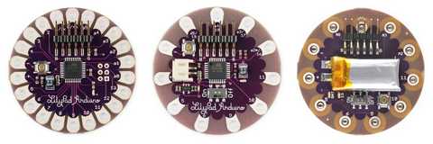
The LilyPad Arduino Main Board is based on the ATmega168V (the low-power version of the ATmega168) or the ATmega328V. The LilyPad Arduino was designed and developed by Leah Buechley and SparkFun Electronics.
The LilyPad Arduino family of boards has been designed for wearable applications. It works on rechargeable batteries and allows easy connection with sensors and actuators developed for an easy integration in clothes and fabrics.
The LilyPad Arduino, LilyPad Arduino Simple and LilyPad Arduino Simple Snap are different from the usual Arduino boards because they need a USB to Serial interface to be programmed. The Arduino USB 2 Serial interface is the one we recommend, but any standard FTDI compatible interface is suitable. The Arduino USB 2 Serial interface behaves as an Arduino UNO and shares the same drivers.
The LilyPad Arduino, LilyPad Arduino Simple and LilyPad Arduino Simple Snap are programmed using the Arduino Software (IDE), our Integrated Development Environment common to all our boards and running both online and offline.
Use your LilyPad Arduino, LilyPad Arduino Simple and LilyPad Arduino Simple Snap on the Arduino Web IDE
All Arduino boards, including this one, work out-of-the-box on the Arduino Web Editor, you only need to install Arduino Create Agent to get started.
The Arduino Web Editor is hosted online, therefore it will always be up-to-date with the latest features and support for all boards. Follow this simple guide to start coding on the browser and upload your sketches onto your board.
Use your LilyPad Arduino, LilyPad Arduino Simple and LilyPad Arduino Simple Snap on the Arduino Desktop IDE
If you want to program your LilyPad Arduino, LilyPad Arduino Simple and LilyPad Arduino Simple Snap while offline you need to install the Arduino Desktop IDE.
Connect the board
Connect the Arduino board to your computer using the USB 2 Serial adapter and a USB cable.
Open your first sketch
Open the LED blink example sketch: File > Examples >01.Basics > Blink.
Select your board type and port
You'll need to select the entry in the Tools > Board menu that corresponds to your Arduino board.
Upload the program
Now, simply click the "Upload" button in the environment. Wait a few seconds - you should see the RX and TX leds on the USB 2 Serial board flashing. If the upload is successful, the message "Done uploading." will appear in the status bar.
Getting Started w/ LilyPad Arduino on Windows
Get a LilyPad Arduino, FTDI board, and USB cable.
In this tutorial, we assume you're using a LilyPad Arduino Main Board, Simple Board, or SimpleSnap. This tutorial will also work for the LilyPad Arduino Protosnap boards: the ProtoSnap LilyPad Development Board and the Protosnap LilyPad Simple Board. If you have a LilyPad Arduino USB, read the corresponding page in the getting started guide for setup instructions.
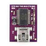
You'll also need a standard mini USB cable and an FTDI board.
Download the Arduino environment
Get the latest version from the download page.
When the download is finished, extract all of the contents of the .zip file to a location you will remember. The Desktop or the Program Files folder are good locations.
Once the .zip file is extracted to a folder titled something like "arduino - 1.0.x", double-click the folder to open it. Make sure that there are a few files and sub-folders inside it including an arduino.exe file.
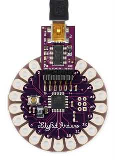
Connect the board
Attach the FTDI board to your LilyPad Arduino board. Attach one end of the USB cable to your FTDI board and the other end to a USB port on your computer.
Install the drivers
You will need to install the drivers for the FTDI board that enables you to program the LilyPad Arduino. You need to download the latest version of the drivers from the FTDI website.
Scroll down to the middle of this page, where there is a table listing drivers for different computers. Click on the most recent driver that is compatible with your computer.
If your computer is using Windows 7, Windows Vista, Windows XP, or an earlier operating system, see this website to determine whether you should use the x86 (32 bit) or x64 (64 bit) drivers. If your computer is using Windows 8 or a later operating system, you should download the x64(64 bit drivers).
When the download is finished, extract all of the contents of the .zip file to a location you will remember.
Follow the guide on the FTDI website that corresponds to your operating system to complete the installation process.
You'll need to restart your computer after installing the drivers.
Launch the Arduino application
Browse to your folder where you saved the Arduino software and double-click the arduino.exe file to open the software.
Upload the program
Now, click the "Upload" button in the Arduino environment. Wait a few seconds - you should see the RX and TX leds on the FTDI board flashing. If the upload is successful, the message "Done uploading." will appear in the status bar.
A few seconds after the upload finishes, you should see the LED on the board start to blink (in green). If it does, congratulations! You've gotten your LilyPad Arduino up-and-running.
If you have problems, see the troubleshooting suggestions.
Additional Resources
lilypadarduino.org: a comprehensive guide to getting started with LilyPad
LilyPad Category on SparkFun: sensors, actuators, and other boards for use with the LilyPad Arduino
Features:
?
5 Digital I/O pins
4 Analog pins
ATMega32U4
Built-in ON/OFF switch
Built-in power supply socket (JST connector) for a 3.7v LiPo battery and charging circuit (no additional battery charger needed)
Simplified layout with less pins, giving more space for sewing or less complex projects
Micro USB connection instead of FTDI header pins
The LilyPad Arduino USB is similar to the LilyPad Arduino Simple Board, but uses a different chip - the ATMega32U4, which has built-in USB support. If the FTDI header pins on other LilyPad Arduinos feel too bulky or FTDI Boards are often lost or misplaced, this board is a great alternative.
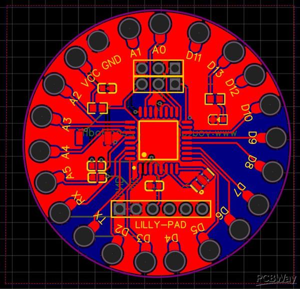
Diy Lillypad Arduino
*PCBWay community is a sharing platform. We are not responsible for any design issues and parameter issues (board thickness, surface finish, etc.) you choose.


- Comments(0)
- Likes(0)
More by Sreeram.zeno
-
 Esp12-F Cluster V1.0
The ESP8266 is a low-cost Wi-Fi microchip, with built-in TCP/IP networking software, and microcontro...
Esp12-F Cluster V1.0
The ESP8266 is a low-cost Wi-Fi microchip, with built-in TCP/IP networking software, and microcontro...
-
 TB6612FNG Motor Driver
The TB6612FNG Motor Driver can control up to two DC motors at a constant current of 1.2A (3.2A peak)...
TB6612FNG Motor Driver
The TB6612FNG Motor Driver can control up to two DC motors at a constant current of 1.2A (3.2A peak)...
-
 Sunny Buddy Solar Charger v1.0
This is the Sunny Buddy, a maximum power point tracking (MPPT) solar charger for single-cell LiPo ba...
Sunny Buddy Solar Charger v1.0
This is the Sunny Buddy, a maximum power point tracking (MPPT) solar charger for single-cell LiPo ba...
-
 Diy 74HC4051 8 Channel Mux Breakout Pcb
The 74HC4051; 74HCT4051 is a single-pole octal-throw analog switch (SP8T) suitable for use in analog...
Diy 74HC4051 8 Channel Mux Breakout Pcb
The 74HC4051; 74HCT4051 is a single-pole octal-throw analog switch (SP8T) suitable for use in analog...
-
 Diy RFM97CW Breakout Pcb
IntroductionLoRa? (standing for Long Range) is a LPWAN technology, characterized by a long range ass...
Diy RFM97CW Breakout Pcb
IntroductionLoRa? (standing for Long Range) is a LPWAN technology, characterized by a long range ass...
-
 ProMicro-RP2040 Pcb
The RP2040 is a 32-bit dual ARM Cortex-M0+ microcontroller integrated circuit by Raspberry Pi Founda...
ProMicro-RP2040 Pcb
The RP2040 is a 32-bit dual ARM Cortex-M0+ microcontroller integrated circuit by Raspberry Pi Founda...
-
 Serial Basic CH340G Pcb
A USB adapter is a type of protocol converter that is used for converting USB data signals to and fr...
Serial Basic CH340G Pcb
A USB adapter is a type of protocol converter that is used for converting USB data signals to and fr...
-
 Mp3 Shield For Arduino
Hardware OverviewThe centerpiece of the MP3 Player Shield is a VS1053B Audio Codec IC. The VS1053B i...
Mp3 Shield For Arduino
Hardware OverviewThe centerpiece of the MP3 Player Shield is a VS1053B Audio Codec IC. The VS1053B i...
-
 MRK CAN Shield Arduino
The CAN-BUS Shield provides your Arduino or Redboard with CAN-BUS capabilities and allows you to hac...
MRK CAN Shield Arduino
The CAN-BUS Shield provides your Arduino or Redboard with CAN-BUS capabilities and allows you to hac...
-
 AVR ISP Programmer
AVR is a family of microcontrollers developed since 1996 by Atmel, acquired by Microchip Technology ...
AVR ISP Programmer
AVR is a family of microcontrollers developed since 1996 by Atmel, acquired by Microchip Technology ...
-
 Diy Arduino mega Pcb
The Arduino Mega 2560 is a microcontroller board based on the ATmega2560. It has 54 digital input/ou...
Diy Arduino mega Pcb
The Arduino Mega 2560 is a microcontroller board based on the ATmega2560. It has 54 digital input/ou...
-
 Max3232 Breakout Board
MAX3232 IC is extensively used for serial communication in between Microcontroller and a computer fo...
Max3232 Breakout Board
MAX3232 IC is extensively used for serial communication in between Microcontroller and a computer fo...
-
 Line Follower Pcb
The Line Follower Array is a long board consisting of eight IR sensors that have been configured to ...
Line Follower Pcb
The Line Follower Array is a long board consisting of eight IR sensors that have been configured to ...
-
 HMC6343 Accelerometer Module
The HMC6343 is a solid-state compass module with tilt compensation from Honeywell. The HMC6343 has t...
HMC6343 Accelerometer Module
The HMC6343 is a solid-state compass module with tilt compensation from Honeywell. The HMC6343 has t...
-
 RTK2 GPS Module For Arduino
USBThe USB C connector makes it easy to connect the ZED-F9P to u-center for configuration and quick ...
RTK2 GPS Module For Arduino
USBThe USB C connector makes it easy to connect the ZED-F9P to u-center for configuration and quick ...
-
 Arduino Explora Pcb
The Arduino Esplora is a microcontroller board derived from the Arduino Leonardo. The Esplora differ...
Arduino Explora Pcb
The Arduino Esplora is a microcontroller board derived from the Arduino Leonardo. The Esplora differ...
-
 Diy Stepper Motor Easy Driver
A motor controller is a device or group of devices that can coordinate in a predetermined manner the...
Diy Stepper Motor Easy Driver
A motor controller is a device or group of devices that can coordinate in a predetermined manner the...
-
 Diy Arduino Pro Mini
The Arduino Pro Mini is a microcontroller board based on the ATmega168 . It has 14 digital input/out...
Diy Arduino Pro Mini
The Arduino Pro Mini is a microcontroller board based on the ATmega168 . It has 14 digital input/out...
-
-
-
-
Tester for Touch Screen Digitizer without using microcontroller
330 2 2 -
Audio reactive glow LED wristband/bracelet with NFC / RFID-Tags
310 0 1 -
-
-


