
|
Y16271K00000T9RVishay Foil Resistors (Division of Vishay Precision Group)
|
x 3 | |

|
106CKR063MIllinois Capacitor
|
x 3 | |

|
AMS1117-5 |
x 1 | |

|
74LVC1G74DC,125Nexperia
|
x 1 | |
|
|
SD Card Slot |
x 1 | |

|
16 pin female header |
x 2 |

|
arduino IDEArduino
|
Diy SD Card Module For Arduino
Micro SD Card Adapter Module


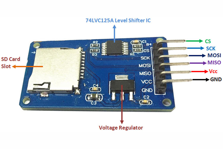
Micro SD Card Adapter Module
Micro SD Card Adapter Module Pinout
SD cards or Micro SD cards are widely used in various applications, such as data logging, data visualization, and many more. Micro SD Card Adapter modules make it easier for us to access these SD cards with ease. The Micro SD Card Adapter module is an easy-to-use module with an SPI interface and an on-board 3.3V voltage regulator to provide proper supply to the SD card.
Features and Specifications of Micro SD Card Adapter Module
This section mentions some of the features and specifications of the Micro SD Card Adapter Module.
Operating Voltage: 4.5V - 5.5V DC
Current Requirement: 0.2-200 mA
3.3 V on-board Voltage Regulator
Supports FAT file system
Supports micro SD up to 2GB
Supports Micro SDHC up to 32GB
Pin Configuration of Micro SD Card Adapter Module
The module contains 6 pins for power and communicating with the controller.
The table below describes the pin type and role of each pin on the module.
GND - Ground
VCC - Voltage Input
MISO - Master In Slave Out(SPI)
MOSI - Master Out Slave In(SPI)
SCK - Serial Clock(SPI)
CS - Chip Select(SPI)
Connecting Micro SD Card Adapter Module to an MCU/MPU
A Micro SD Card adapter module can be easily connected to an MCU/MPU. Since the module communicates via the SPI protocol, we need to connect the MISO, MOSI, SCK, and CS of the module to the MCU’s.
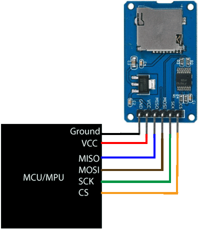
The image can be seen as a reference and the connections can be made based upon that. Along with the SD card holder, the module has a 3.3V voltage regulator, along with a 74LVC125A Level shifter IC.
Alternatives for Micro SD Card Adapter Module
MOD100717 Micro SD card module, Mini Micro SD Card Reader Module
Applications of Micro SD Card Adapter Module
Here are some of the applications of the Micro SD Card Adapter Module.
Data loggers
Audio, Video storage, and Visualization
Expandable memory
2D Model of Micro SD Card Adapter Module
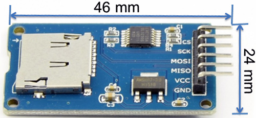
Below is the 2D model of the SD card adapter module along with its dimensions in millimeters. This information can be used to create custom footprints of the module and can be used for PCB Designing and CAD modelling.
The operating voltage of any standard micro SD Cards is 3.3 V. So we cannot directly connect it to circuits that use 5V logic. In fact, any voltages exceeding 3.6V will permanently damage the micro SD card. That’s why; the module has an onboard ultra-low dropout regulator that will convert voltages from 3.3V – 6V down to ~3.3V.
There’s also a 74LVC125A chip on the module which converts the interface logic from 3.3V-5V to 3.3V. This is called logic level shifting. That means you can use this board to interact with both 3.3V and 5V microcontrollers like Arduino.
Preparing the micro SD card
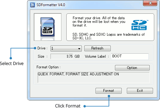
Before you insert the micro SD card into the module and hook it up to the Arduino, you must properly format the card. For the Arduino library we’ll be discussing, and nearly every other SD library, the card must be formatted FAT16 or FAT32.
If you have a new SD card, chances are it’s already pre-formatted with a FAT file system. However you may have problems with how the factory formats the card, or if it’s an old card it needs to be reformatted. Either way, it’s always good idea to format the card before using, even if it’s new!
We strongly recommend you use the official SD card formatter utility – written by the SD association it solves many problems that come with bad formatting! Download the formatter and run it on your computer, just select the right drive and click FORMAT.
Wiring – Connecting Micro SD Card Module to Arduino
Now that your card is ready to use, we can wire up the micro SD breakout board!
To start with, insert the micro SD card module into the breadboard. Connect VCC pin on the module to 5V on the Arduino and GND pin to ground. Now we are remaining with the pins that are used for SPI communication.
As micro SD cards require a lot of data transfer, they will give the best performance when connected up to the hardware SPI pins on a microcontroller. The hardware SPI pins are much faster than ‘bit-banging’ the interface code using another set of pins.
Note that each Arduino Board has different SPI pins which should be connected accordingly. For Arduino boards such as the UNO/Nano those pins are digital 13 (SCK), 12 (MISO) and 11 (MOSI). You will also need a fourth pin for the ‘chip/slave select’ (SS) line.
Usually this is pin 10 but you can actually use any pin you like.
If you have a Mega, the pins are different! You’ll want to use digital 50 (MISO), 51 (MOSI), 52 (SCK), and 53 (SS). Refer below table for quick understanding.
Arduino Code – Testing the SD card module with CardInfo
Communicating with an SD card is a bunch of work, but luckily for us, Arduino IDE already contains a very nice library called SD which simplifies reading from and writing to SD cards. You can see it in the Examples submenu.
Next, select the CardInfo example sketch.
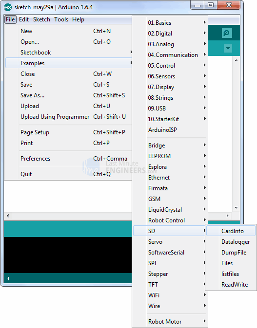
This sketch will not write any data to the card. It just tells you if it managed to recognize the card, and displays some information about it. This can be very useful when trying to figure out whether an SD card is supported. Before trying out any new card, we recommend you to run this sketch once!
Go to the beginning of the sketch and make sure that the chipSelect line is correctly initialized, in our case we’re using digital pin #10 so change it to 10!
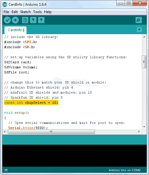
OK, now insert the SD card into the module and upload the sketch.
As soon as you open the Serial Monitor, you’ll probably get something like the following:
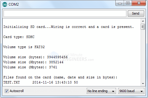
You may find it gibberish, but it’s useful to see the card type is SDHC (SD High Capacity), Volume type is FAT32 as well as the size of the card about 4 GB etc.
If you have a bad card, which seems to happen more with clone versions, you might see:
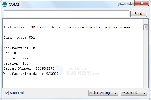
The card mostly responded, but the data is all bad. See there is no Manufacturer ID / OEM ID and the Product ID is ‘N/A’. This shows that the card returned some SD errors. It’s basically a bad scene. If you get something like this, you can try to reformat it or if it still flakes out, you should toss the card.
Finally, try taking out the SD card and running the sketch again, you’ll get the following,
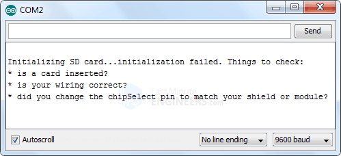
See, it couldn’t even initialize the SD card. This can also happen if there’s a wiring error or if the card is permanently damaged.
If the wiring is correct but the SD card is not properly formatted, you’ll get something like this:
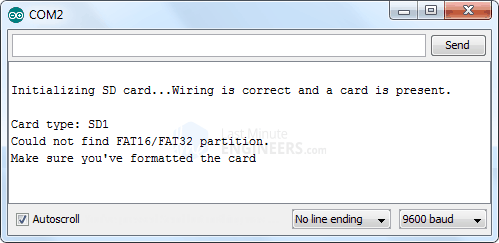
code for sd card with arduino
#include <SPI.h>
#include <SD.h>
File myFile;
// change this to match your SD shield or module;
const int chipSelect = 10;
void setup()
{
// Open serial communications and wait for port to open:
Serial.begin(9600);
while (!Serial) {
; // wait for serial port to connect. Needed for Leonardo only
}
Serial.print("Initializing SD card...");
if (!SD.begin()) {
Serial.println("initialization failed!");
return;
}
Serial.println("initialization done.");
// open the file. note that only one file can be open at a time,
// so you have to close this one before opening another.
myFile = SD.open("test.txt", FILE_WRITE);
// if the file opened okay, write to it:
if (myFile) {
Serial.print("Writing to test.txt...");
myFile.println("testing 1, 2, 3.");
// close the file:
myFile.close();
Serial.println("done.");
} else {
// if the file didn't open, print an error:
Serial.println("error opening test.txt");
}
// re-open the file for reading:
myFile = SD.open("test.txt");
if (myFile) {
Serial.println("test.txt:");
// read from the file until there's nothing else in it:
while (myFile.available()) {
Serial.write(myFile.read());
}
// close the file:
myFile.close();
} else {
// if the file didn't open, print an error:
Serial.println("error opening test.txt");
}
}
void loop()
{
// nothing happens after setup
}


Diy SD Card Module For Arduino
*PCBWay community is a sharing platform. We are not responsible for any design issues and parameter issues (board thickness, surface finish, etc.) you choose.

Raspberry Pi 5 7 Inch Touch Screen IPS 1024x600 HD LCD HDMI-compatible Display for RPI 4B 3B+ OPI 5 AIDA64 PC Secondary Screen(Without Speaker)
BUY NOW
ESP32-S3 4.3inch Capacitive Touch Display Development Board, 800×480, 5-point Touch, 32-bit LX7 Dual-core Processor
BUY NOW
Raspberry Pi 5 7 Inch Touch Screen IPS 1024x600 HD LCD HDMI-compatible Display for RPI 4B 3B+ OPI 5 AIDA64 PC Secondary Screen(Without Speaker)
BUY NOW- Comments(0)
- Likes(1)
 Log in to post comments.
-
 zoltan.topa
Feb 15,2024
- 0 USER VOTES
- YOUR VOTE 0.00 0.00
- 1
- 2
- 3
- 4
- 5
- 6
- 7
- 8
- 9
- 10
- 1
- 2
- 3
- 4
- 5
- 6
- 7
- 8
- 9
- 10
- 1
- 2
- 3
- 4
- 5
- 6
- 7
- 8
- 9
- 10
- 1
- 2
- 3
- 4
- 5
- 6
- 7
- 8
- 9
- 10
 More by Sreeram.zeno
-
 Line Follower Pcb
The Line Follower Array is a long board consisting of eight IR sensors that have been configured to ...
-
 HMC6343 Accelerometer Module
The HMC6343 is a solid-state compass module with tilt compensation from Honeywell. The HMC6343 has t...
-
 RTK2 GPS Module For Arduino
USBThe USB C connector makes it easy to connect the ZED-F9P to u-center for configuration and quick ...
-
 Arduino Explora Pcb
The Arduino Esplora is a microcontroller board derived from the Arduino Leonardo. The Esplora differ...
-
 Diy Stepper Motor Easy Driver
A motor controller is a device or group of devices that can coordinate in a predetermined manner the...
-
 Diy Arduino Pro Mini
The Arduino Pro Mini is a microcontroller board based on the ATmega168 . It has 14 digital input/out...
-
 Esp12-F Cluster V1.0
The ESP8266 is a low-cost Wi-Fi microchip, with built-in TCP/IP networking software, and microcontro...
-
 TB6612FNG Motor Driver
The TB6612FNG Motor Driver can control up to two DC motors at a constant current of 1.2A (3.2A peak)...
-
 Sunny Buddy Solar Charger v1.0
This is the Sunny Buddy, a maximum power point tracking (MPPT) solar charger for single-cell LiPo ba...
-
 Diy 74HC4051 8 Channel Mux Breakout Pcb
The 74HC4051; 74HCT4051 is a single-pole octal-throw analog switch (SP8T) suitable for use in analog...
-
 Diy RFM97CW Breakout Pcb
IntroductionLoRa? (standing for Long Range) is a LPWAN technology, characterized by a long range ass...
-
 ProMicro-RP2040 Pcb
The RP2040 is a 32-bit dual ARM Cortex-M0+ microcontroller integrated circuit by Raspberry Pi Founda...
-
 Serial Basic CH340G Pcb
A USB adapter is a type of protocol converter that is used for converting USB data signals to and fr...
-
 Mp3 Shield For Arduino
Hardware OverviewThe centerpiece of the MP3 Player Shield is a VS1053B Audio Codec IC. The VS1053B i...
-
 MRK CAN Shield Arduino
The CAN-BUS Shield provides your Arduino or Redboard with CAN-BUS capabilities and allows you to hac...
-
 AVR ISP Programmer
AVR is a family of microcontrollers developed since 1996 by Atmel, acquired by Microchip Technology ...
-
 Diy Arduino mega Pcb
The Arduino Mega 2560 is a microcontroller board based on the ATmega2560. It has 54 digital input/ou...
-
 Max3232 Breakout Board
MAX3232 IC is extensively used for serial communication in between Microcontroller and a computer fo...
-
 Line Follower Pcb
The Line Follower Array is a long board consisting of eight IR sensors that have been configured to ...
-
 HMC6343 Accelerometer Module
The HMC6343 is a solid-state compass module with tilt compensation from Honeywell. The HMC6343 has t...
-
 RTK2 GPS Module For Arduino
USBThe USB C connector makes it easy to connect the ZED-F9P to u-center for configuration and quick ...
-
 Arduino Explora Pcb
The Arduino Esplora is a microcontroller board derived from the Arduino Leonardo. The Esplora differ...
-
 Diy Stepper Motor Easy Driver
A motor controller is a device or group of devices that can coordinate in a predetermined manner the...
-
 Diy Arduino Pro Mini
The Arduino Pro Mini is a microcontroller board based on the ATmega168 . It has 14 digital input/out...
-
 Esp12-F Cluster V1.0
The ESP8266 is a low-cost Wi-Fi microchip, with built-in TCP/IP networking software, and microcontro...
-
 TB6612FNG Motor Driver
The TB6612FNG Motor Driver can control up to two DC motors at a constant current of 1.2A (3.2A peak)...
-
 Sunny Buddy Solar Charger v1.0
This is the Sunny Buddy, a maximum power point tracking (MPPT) solar charger for single-cell LiPo ba...
-
 Diy 74HC4051 8 Channel Mux Breakout Pcb
The 74HC4051; 74HCT4051 is a single-pole octal-throw analog switch (SP8T) suitable for use in analog...
-
 Diy RFM97CW Breakout Pcb
IntroductionLoRa? (standing for Long Range) is a LPWAN technology, characterized by a long range ass...
-
 ProMicro-RP2040 Pcb
The RP2040 is a 32-bit dual ARM Cortex-M0+ microcontroller integrated circuit by Raspberry Pi Founda...
-
Commodore 64 1541-II Floppy Disk Drive C64 Power Supply Unit USB-C 5V 12V DIN connector 5.25
124 1 2 -
Easy to print simple stacking organizer with drawers
74 0 0 -
-
-
-
Modifying a Hotplate to a Reflow Solder Station
1116 1 6 -
MPL3115A2 Barometric Pressure, Altitude, and Temperature Sensor
627 0 1 -
-
Nintendo 64DD Replacement Shell
478 0 2 -
V2 Commodore AMIGA USB-C Power Sink Delivery High Efficiency Supply Triple Output 5V ±12V OLED display ATARI compatible shark 100W
1398 4 3


