|
arduino IDEArduino
|
Diy Water Level Sensor
Hardware Overview
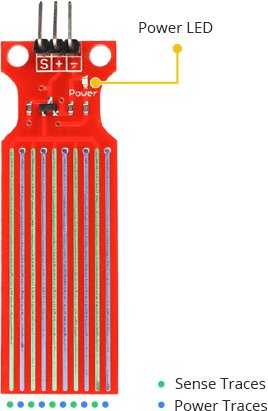
The sensor has a series of ten exposed copper traces, five of which are power traces and five are sense traces.
These traces are interlaced so that there is one sense trace between every two power traces.
Usually these traces are not connected but are bridged by water when submerged.

There’s a Power LED on the board which will light up when the board is powered.
How Water Level Sensor Works?
The working of the water level sensor is pretty straightforward.
The series of exposed parallel conductors, together acts as a variable resistor (just like a potentiometer) whose resistance varies according to the water level.
The change in resistance corresponds to the distance from the top of the sensor to the surface of the water.
The resistance is inversely proportional to the height of the water:
The more water the sensor is immersed in, results in better conductivity and will result in a lower resistance.
The less water the sensor is immersed in, results in poor conductivity and will result in a higher resistance.
The sensor produces an output voltage according to the resistance, which by measuring we can determine the water level.
Water Level Sensor Pinout
The water level sensor is super easy to use and only has 3 pins to connect.
S (Signal) pin is an analog output that will be connected to one of the analog inputs on your Arduino.
+ (VCC) pin supplies power for the sensor. It is recommended to power the sensor with between 3.3V – 5V. Please note that the analog output will vary depending on what voltage is provided for the sensor.
– (GND) is a ground connection.
Wiring Water Level Sensor with Arduino
Let’s hook the water level sensor up to the Arduino.
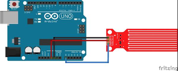
First you need to supply power to the sensor. For that you can connect the + (VCC) pin on the module to 5V on the Arduino and – (GND) pin to ground.
However, one commonly known issue with these sensors is their short lifespan when exposed to a moist environment. Having power applied to the probe constantly speeds the rate of corrosion significantly.
To overcome this, we recommend that you do not power the sensor constantly, but power it only when you take the readings.
An easy way to accomplish this is to connect the VCC pin to a digital pin of an Arduino and set it to HIGH or LOW as per your requirement. So, we’ll connect the VCC pin to the digital pin #7 of an Arduino.
Finally, connect the S (Signal) pin to the A0 ADC pin on your Arduino.
The following illustration shows the wiring.

Water Level Sensing Basic Example
Once the circuit is built, upload the following sketch to your Arduino.
// Sensor pins
#define sensorPower 7
#define sensorPin A0
// Value for storing water level
int val = 0;
void setup() {
// Set D7 as an OUTPUT
pinMode(sensorPower, OUTPUT);
// Set to LOW so no power flows through the sensor
digitalWrite(sensorPower, LOW);
Serial.begin(9600);
}
void loop() {
//get the reading from the function below and print it
int level = readSensor();
Serial.print("Water level: ");
Serial.println(level);
delay(1000);
}
//This is a function used to get the reading
int readSensor() {
digitalWrite(sensorPower, HIGH); // Turn the sensor ON
delay(10); // wait 10 milliseconds
val = analogRead(sensorPin); // Read the analog value form sensor
digitalWrite(sensorPower, LOW); // Turn the sensor OFF
return val; // send current reading
}
Once the sketch is uploaded, open a Serial Monitor window to see the output from the Arduino. You should see a value 0 when the sensor is not touching anything. To see it sense water, you can take a glass of water and slowly put the sensor in it.
The sensor is not designed to be fully submersed, be careful to install it so that only the exposed traces on the PCB will come in contact with water.
Explanation:
The sketch begins with the declaration of the Arduino pins to which the sensor’s + (VCC) and S (signal) pins are connected.
#define sensorPower 7
#define sensorPin A0
Next, we define a variable val that stores the current water level.
int val = 0;
Now in the Setup section, we first declare the power connection to the sensor as output, then we set it low so no power flows through the sensor initially. We also setup the serial monitor.
pinMode(sensorPower, OUTPUT);
digitalWrite(sensorPower, LOW);
Serial.begin(9600);
In the loop section, we call readSensor() function repeatedly at the interval of one second and print the returned value.
Serial.print("Water level: ");
Serial.println(readSensor());
delay(1000);
The readSensor() function is used to get the current water level. It turns the sensor ON, waits for 10 milliseconds, reads the analog value form sensor, turns the sensor OFF and then returns the analog value.
int readSensor() {
digitalWrite(sensorPower, HIGH);
delay(10);
val = analogRead(sensorPin);
digitalWrite(sensorPower, LOW);
return val;
}
Calibration
To get accurate readings out of your water level sensor, it is recommended that you first calibrate it for the particular type of water that you plan to monitor.
As you know pure water is not conductive. It’s actually the minerals and impurities in water that makes it conductive. So, your sensor may be more or less sensitive depending on the type of water you use.
Before you start storing data or triggering events, you should see what readings you are actually getting from your sensor.
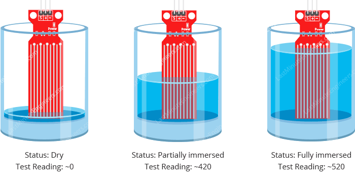
Using the sketch above, note what values your sensor outputs when the sensor is completely dry -vs- when it is partially submerged in the water -vs- when it is completely submerged.
For example, using the same circuit above, you’ll see the close to the following values in the serial monitor when the senor is dry (0) and when it is partially submerged in the water (~420) and when it is completely submerged (~520).

This test may take some trial and error. Once you get a good handle on these readings, you can use them as threshold if you intend to trigger an action. In the next example, we are going to do just that.
Water Level Sensing Project
For our next example, we’re going to make a portable water level sensor that will light up LEDs according to the water level.
Wiring
We’ll use the circuit from the previous example. This time we just need to add some LEDs.
Connect three LEDs to digital pins #2, #3 and #4 through 220Ω current limiting resistors.
The water level sensor is a device that measures the liquid level in a fixed container that is too high or too low. According to the method of measuring the liquid level, it can be divided into two types: contact type and non-contact type. The input type water level transmitter we call is a contact measurement, which converts the height of the liquid level into an electrical signal for output. It is currently a widely used water level transmitter.

How does the water level sensor work?
The working principle of the water level sensor is that when it is put into a certain depth in the liquid to be measured, the pressure on the sensor’s front surface is converted into the liquid level height. The calculation formula is Ρ=ρ.g.H+Po, in the formula P is the pressure on the liquid surface of the sensor, ρ is the density of the liquid to be measured, g is the local acceleration of gravity, Po is the atmospheric pressure on the liquid surface, and H is the depth at which the sensor drops into the liquid.
Where to use water level sensors?
The uses of water level sensors include the following applications:
1. Water level measurement of pools and water tanks
2. Water level measurement of rivers and lakes
3. Marine level measurement
4. Level measurement of acid-base liquids
5. Oil level measurement of oil trucks and mailboxes
6. Swimming pool water level control
7. Tsunami warning and sea-level monitoring
8. Cooling tower water level control
9. Sewage pump level control
10. Remote monitoring of the liquid level
What are the benefits of water level sensors?
1. Simple structure: There are no movable or elastic elements, so the reliability is extremely high, and there is no need for regular maintenance during use. The operation is simple and convenient.
2. Convenient installation: When using, first connect one end of the wire correctly, and then put the other end of the water level probe into the solution to be measured.
3. Ranges are optional: you can measure the water level in the range of 1-200 meters, and other measurement ranges can also be customized.
4. Wide range of applications: suitable for liquid level measurement of high temperature and high pressure, strong corrosion, high pollution, and other media.
5. Wide range of measuring medium: High-precision measurement can be carried out from the water, oil to paste with high viscosity, and wide-range temperature compensation is not affected by the foaming, deposition, and electrical characteristics of the measured medium.
6. Long service life: Generally, the liquid level sensor can be used for 4-5 years in a normal environment, and it can also be used for 2-3 years in a harsh environment.
7. Strong function: It can be directly connected to the digital display meter to display the value in real-time, or it can be connected to a variety of controllers and set the upper and lower limits to control the water volume in the container.
8. Accurate measurement: The built-in high-quality sensor has high sensitivity, fast response, and accurately reflects the subtle changes of the flowing or static liquid level, and the measurement accuracy is high.
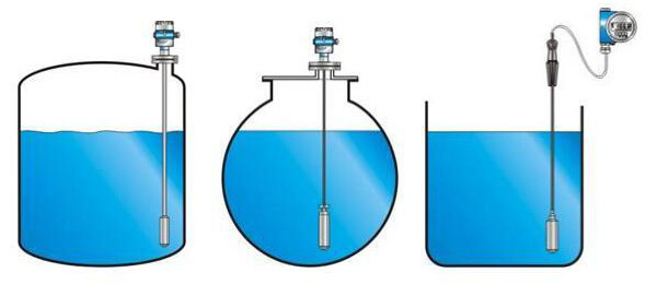
9. Variety of types: liquid level sensors have various structural designs such as input type, straight rod type, flange type, thread type, inductive type, screw-in type, and float type. It can meet the measurement needs of all different places.
1. Optical water level sensor
The optical sensor is solid-state. They use infrared LEDs and phototransistors, and when the sensor is in the air, they are optically coupled. When the sensor head is immersed in the liquid, the infrared light will escape, causing the output to change. These sensors can detect the presence or absence of almost any liquid. They are not sensitive to ambient light, are not affected by foam when in air, and are not affected by small bubbles when in liquid. This makes them useful in situations where state changes must be recorded quickly and reliably, and in situations where they can operate reliably for long periods without maintenance.
Arduino Code
Once the circuit is built, upload the following sketch to your Arduino.
In this sketch two variables are defined viz. lowerThreshold and upperThreshold. These variables represent our threshold levels.
Anything below the lower threshold will trigger the red LED to turn on. Anything above the upper threshold will turn on the green LED. Anything between these will turn on the yellow LED.
/* Change these values based on your calibration values */
int lowerThreshold = 420;
int upperThreshold = 520;
// Sensor pins
#define sensorPower 7
#define sensorPin A0
// Value for storing water level
int val = 0;
// Declare pins to which LEDs are connected
int redLED = 2;
int yellowLED = 3;
int greenLED = 4;
void setup() {
Serial.begin(9600);
pinMode(sensorPower, OUTPUT);
digitalWrite(sensorPower, LOW);
// Set LED pins as an OUTPUT
pinMode(redLED, OUTPUT);
pinMode(yellowLED, OUTPUT);
pinMode(greenLED, OUTPUT);

Diy Water Level Sensor
*PCBWay community is a sharing platform. We are not responsible for any design issues and parameter issues (board thickness, surface finish, etc.) you choose.

Raspberry Pi 5 7 Inch Touch Screen IPS 1024x600 HD LCD HDMI-compatible Display for RPI 4B 3B+ OPI 5 AIDA64 PC Secondary Screen(Without Speaker)
BUY NOW
ESP32-S3 4.3inch Capacitive Touch Display Development Board, 800×480, 5-point Touch, 32-bit LX7 Dual-core Processor
BUY NOW
Raspberry Pi 5 7 Inch Touch Screen IPS 1024x600 HD LCD HDMI-compatible Display for RPI 4B 3B+ OPI 5 AIDA64 PC Secondary Screen(Without Speaker)
BUY NOW- Comments(0)
- Likes(0)
 Log in to post comments.
- 0 USER VOTES
- YOUR VOTE 0.00 0.00
- 1
- 2
- 3
- 4
- 5
- 6
- 7
- 8
- 9
- 10
- 1
- 2
- 3
- 4
- 5
- 6
- 7
- 8
- 9
- 10
- 1
- 2
- 3
- 4
- 5
- 6
- 7
- 8
- 9
- 10
- 1
- 2
- 3
- 4
- 5
- 6
- 7
- 8
- 9
- 10
 More by Sreeram.zeno
-
 Line Follower Pcb
The Line Follower Array is a long board consisting of eight IR sensors that have been configured to ...
-
 HMC6343 Accelerometer Module
The HMC6343 is a solid-state compass module with tilt compensation from Honeywell. The HMC6343 has t...
-
 RTK2 GPS Module For Arduino
USBThe USB C connector makes it easy to connect the ZED-F9P to u-center for configuration and quick ...
-
 Arduino Explora Pcb
The Arduino Esplora is a microcontroller board derived from the Arduino Leonardo. The Esplora differ...
-
 Diy Stepper Motor Easy Driver
A motor controller is a device or group of devices that can coordinate in a predetermined manner the...
-
 Diy Arduino Pro Mini
The Arduino Pro Mini is a microcontroller board based on the ATmega168 . It has 14 digital input/out...
-
 Esp12-F Cluster V1.0
The ESP8266 is a low-cost Wi-Fi microchip, with built-in TCP/IP networking software, and microcontro...
-
 TB6612FNG Motor Driver
The TB6612FNG Motor Driver can control up to two DC motors at a constant current of 1.2A (3.2A peak)...
-
 Sunny Buddy Solar Charger v1.0
This is the Sunny Buddy, a maximum power point tracking (MPPT) solar charger for single-cell LiPo ba...
-
 Diy 74HC4051 8 Channel Mux Breakout Pcb
The 74HC4051; 74HCT4051 is a single-pole octal-throw analog switch (SP8T) suitable for use in analog...
-
 Diy RFM97CW Breakout Pcb
IntroductionLoRa? (standing for Long Range) is a LPWAN technology, characterized by a long range ass...
-
 ProMicro-RP2040 Pcb
The RP2040 is a 32-bit dual ARM Cortex-M0+ microcontroller integrated circuit by Raspberry Pi Founda...
-
 Serial Basic CH340G Pcb
A USB adapter is a type of protocol converter that is used for converting USB data signals to and fr...
-
 Mp3 Shield For Arduino
Hardware OverviewThe centerpiece of the MP3 Player Shield is a VS1053B Audio Codec IC. The VS1053B i...
-
 MRK CAN Shield Arduino
The CAN-BUS Shield provides your Arduino or Redboard with CAN-BUS capabilities and allows you to hac...
-
 AVR ISP Programmer
AVR is a family of microcontrollers developed since 1996 by Atmel, acquired by Microchip Technology ...
-
 Diy Arduino mega Pcb
The Arduino Mega 2560 is a microcontroller board based on the ATmega2560. It has 54 digital input/ou...
-
 Max3232 Breakout Board
MAX3232 IC is extensively used for serial communication in between Microcontroller and a computer fo...
-
 Line Follower Pcb
The Line Follower Array is a long board consisting of eight IR sensors that have been configured to ...
-
 HMC6343 Accelerometer Module
The HMC6343 is a solid-state compass module with tilt compensation from Honeywell. The HMC6343 has t...
-
 RTK2 GPS Module For Arduino
USBThe USB C connector makes it easy to connect the ZED-F9P to u-center for configuration and quick ...
-
 Arduino Explora Pcb
The Arduino Esplora is a microcontroller board derived from the Arduino Leonardo. The Esplora differ...
-
 Diy Stepper Motor Easy Driver
A motor controller is a device or group of devices that can coordinate in a predetermined manner the...
-
 Diy Arduino Pro Mini
The Arduino Pro Mini is a microcontroller board based on the ATmega168 . It has 14 digital input/out...
-
 Esp12-F Cluster V1.0
The ESP8266 is a low-cost Wi-Fi microchip, with built-in TCP/IP networking software, and microcontro...
-
 TB6612FNG Motor Driver
The TB6612FNG Motor Driver can control up to two DC motors at a constant current of 1.2A (3.2A peak)...
-
 Sunny Buddy Solar Charger v1.0
This is the Sunny Buddy, a maximum power point tracking (MPPT) solar charger for single-cell LiPo ba...
-
 Diy 74HC4051 8 Channel Mux Breakout Pcb
The 74HC4051; 74HCT4051 is a single-pole octal-throw analog switch (SP8T) suitable for use in analog...
-
 Diy RFM97CW Breakout Pcb
IntroductionLoRa? (standing for Long Range) is a LPWAN technology, characterized by a long range ass...
-
 ProMicro-RP2040 Pcb
The RP2040 is a 32-bit dual ARM Cortex-M0+ microcontroller integrated circuit by Raspberry Pi Founda...
-
-
Commodore 64 1541-II 1581 Floppy Disk Drive C64 Power Supply Unit USB-C 5V 12V DIN connector 5.25
181 1 3 -
Easy to print simple stacking organizer with drawers
88 0 0 -
-
-
-
Modifying a Hotplate to a Reflow Solder Station
1155 1 6 -
MPL3115A2 Barometric Pressure, Altitude, and Temperature Sensor
646 0 1 -
-
Nintendo 64DD Replacement Shell
498 0 2 -
V2 Commodore AMIGA USB-C Power Sink Delivery High Efficiency Supply Triple Output 5V ±12V OLED display ATARI compatible shark 100W
1467 4 3


