|
|
Espressif ESP32 Development Board |
x 2 | |
|
|
GC9A01 Round Display |
x 2 | |
|
|
1N4007TWGMC
|
x 2 | |
|
|
Resistor 10k ohm |
x 2 | |
|
|
Resistor 220 ohm |
x 2 | |
|
|
Resistor 220 ohm |
x 2 |

|
Soldering Iron Kit |
|

|
arduino IDEArduino
|
ESP32 Analog style VU meter with GC9A01 Round Dispalys + Peak Meters
A typical VU meter measures audio signals and displays them with a visual indicator. In the classic VU meter design is used a moving needle (actually a sensitive galvanometer) that points to a scale on a calibrated range.

The needle moves left or right depending on the strength of the audio signal. I recently acquired these small round TFT displays with a GC9A01 chip. Its basic purpose is for making smart watches, but in fact their shape is ideally suited for making a retro-look VU meter. My attention was drawn to a project on thesolaruniverse blog, which describes in detail how to create meters gauges and dials on this display with arduino nano.
For the needs of this project I made some modifications to the code but basically kept the beautiful retro design and colors. Now, instead of random values, the instrument shows the real values of the voltage applied to the input pin of the microcontroller. For a more homogeneous movement of the needle, I now use a more powerful ESP32 microcontroller.

This project is sponsored by PCBWay. This year, PCBWay is organizing the 11th badge design contest from March 3rd to April 31st. Follow the design requirements and Submit your designs in one of the given ways, and become the winner of one of the valuable prizes in cash and cupons. This contest is more than a competition—it’s a celebration of 11 years of innovation and a chance to dream about the boundless possibilities ahead with PCBWay.

Nowadays the price of ESP32 is very low, so for better separation of the channels I decided to use a separate microcontroller for each channel. In this project I also added a peak meter that signals the moment of exceeding the permitted level of the signal with an LED.
The device is very simple to make and consists of several components:
- ESP32 microcontroller - two pieces
- Two round displays with GC9A01 and 240x240 resolution
- envelope followers made with two small signal diodes and two capacitors
- and two leds with current limiting resistors

In particular, in this case I use the simplest passive envelope follower consisting of a diode and a capacitor, because the whole device is mainly intended as a demo device for testing, and based on this idea, a precise, fully functional audio VU meter can be made later with certain software and hardware modifications.
And now let's see how this VU meter works in real conditions.

Let me mention that a stereo potentiometer can be placed on the input in order to regulate the signal level, but for the sake of simplification I do it with the Windows mixer software.
And finally a short conclusion: This small, simple and interesting arduino project can be made in a few hours, and has a beautiful retro look, so you can use it as an additional part of any audio device, or as a stand-alone unit. With minimal code modification it can be used on many other devices (eg radio receiver) where signal strength measurement is required. The Vu meter is built in a suitable plastic box made of PVC material and lined with self-adhesive colored wallpaper.
// GCA901_Nano_voltage_meter // // grid voltage variation monitor (230V - 250V AC) // rolling averaged voltage (of 10 readings) is sent to display // NOTE: here voltage generated with random function // // microcontroller: Arduino Nano // display 240*240 circular SPI 3.3V TFT with GC9A01 controller // // note: random function drives fluctuations of the parameter named 'volt' // CG9A01 Arduino Nano // RST -------- NC // CST -------- 10 // DC --------- 9 // SDA -------- 11 - green wire // SCL -------- 13 - yellow wire // // Floris Wouterlood // September 1, 2023 // public domain // made for a 240*240 pixel circular display // all x-y-coordinates relative to center = x = 120 and y = 120 Adafruit_GC9A01A tft (TFT_CS, TFT_DC); const int vlez = 34; //int vlez; int sig = 0; int multiplier; int frametime = 100; int x_pos; int y_pos; int center_x = 120; // center x of dial on 240*240 TFT display int center_y = 120; // center y of dial on 240*240 TFT display float pivot_x, pivot_y,pivot_x_old, pivot_y_old; float p1_x,p1_y,p2_x,p2_y,p3_x, p3_y, p4_x, p4_y, p5_x, p5_y; float p1_x_old,p1_y_old, p2_x_old, p2_y_old, p3_x_old, p3_y_old; float p4_x_old, p4_y_old, p5_x_old, p5_y_old; float angleOffset = 3.14; float arc_x; float arc_y; int radius = 120; // center y of circular scale float angle_circle = 0; float needleAngle = 0; int iteration = 0; int j; float volt = 220; int needle_multiplier = 1; float needle_setter; float currentNeedleValue = 230; // Start with a base voltage or level float needleSpeed = 10; // Speed at which the needle returns to the left // to start with void setup() { //randomSeed (analogRead(0)); pinMode(12, OUTPUT); pinMode(vlez, INPUT); tft.begin(); Serial.begin (9600); Serial.println (""); Serial.println (""); tft.setRotation (0); tft.fillScreen (BLACK); tft.drawCircle (center_x, center_y,120, BLACK); pivot_x = center_x; pivot_y = center_y+50; p1_x_old = center_x; p1_y_old = center_y+50; p2_x_old = center_x; p2_y_old = center_y+50; p3_x_old = center_x; p3_y_old = center_y+50; p4_x_old = center_x; p4_y_old = center_y+50; p5_x_old = center_x; p5_y_old = center_y+30; create_dial (); needle_setter = volt; needleAngle = (((needle_setter)*DEG2RAD*1.8)-3.14); needle(); draw_pivot (); } void loop (){ // Map the analog input (voltage) to the needle range float targetNeedleValue = map(analogRead(vlez), 0, 400, 230, 270); Serial.println(targetNeedleValue); sig = analogRead(vlez); if (sig > 280) {digitalWrite(12, HIGH);} else {digitalWrite(12, LOW);} // If the target value is greater than the current needle position, move quickly if (targetNeedleValue > currentNeedleValue) { currentNeedleValue = targetNeedleValue; } // If the target value is lower, move more slowly to simulate damping else if (targetNeedleValue < currentNeedleValue) { currentNeedleValue -= needleSpeed; // Decrease the value gradually if (currentNeedleValue < targetNeedleValue) { currentNeedleValue = targetNeedleValue; // Ensure we don't overshoot } } // Update the needle position needle_setter = currentNeedleValue; needle(); draw_pivot(); delay(frametime); // Control the update rate } void needle (){ // dynamic needle management tft.drawLine (pivot_x, pivot_y, p1_x_old, p1_y_old, AFRICA); // remove old needle tft.fillTriangle (p1_x_old, p1_y_old, p2_x_old, p2_y_old, p3_x_old, p3_y_old, AFRICA); // remove old arrow head tft.fillTriangle (pivot_x, pivot_y, p4_x_old, p4_y_old, p5_x_old, p5_y_old, AFRICA); // remove old arrow head needleAngle = (((needle_setter)*0.01745331*1.8)-3.14); p1_x = (pivot_x + ((radius)*cos(needleAngle))); // needle tip p1_y = (pivot_y + ((radius)*sin(needleAngle))); p2_x = (pivot_x + ((radius-15)*cos(needleAngle-0.05))); // needle triange left p2_y = (pivot_y + ((radius-15)*sin(needleAngle-0.05))); p3_x = (pivot_x + ((radius-15)*cos(needleAngle+0.05))); // needle triange right p3_y = (pivot_y + ((radius-15)*sin(needleAngle+0.05))); p4_x = (pivot_x + ((radius-90)*cos(angleOffset+(needleAngle-0.2)))); // needle triange left p4_y = (pivot_y + ((radius-90)*sin(angleOffset+(needleAngle-0.2)))); p5_x = (pivot_x + ((radius-90)*cos(angleOffset+(needleAngle+0.2)))); // needle triange right p5_y = (pivot_y + ((radius-90)*sin(angleOffset+(needleAngle+0.2)))); p1_x_old = p1_x; p1_y_old = p1_y; // remember previous needle position p2_x_old = p2_x; p2_y_old = p2_y; p3_x_old = p3_x; p3_y_old = p3_y; p4_x_old = p4_x; p4_y_old = p4_y; // remember previous needle counterweight position p5_x_old = p5_x; p5_y_old = p5_y; tft.drawLine (pivot_x, pivot_y, p1_x, p1_y, BLACK); // create needle tft.fillTriangle (p1_x, p1_y, p2_x, p2_y, p3_x, p3_y, BLACK); // create needle tip pointer // tft.drawLine (center_x-80, center_y+70, center_x+80,center_y+70, BLACK); // repair floor tft.fillTriangle (pivot_x, pivot_y, p4_x, p4_y, p5_x, p5_y, BLACK); // create needle counterweight } void create_dial (){ tft.fillCircle (center_x, center_y,120, AFRICA); // general dial field tft.drawCircle (center_x, center_y,118,GREY); tft.drawCircle (center_x, center_y,117,BLACK); tft.drawCircle (center_x, center_y,116,BLACK); tft.drawCircle (center_x, center_y,115,GREY); for (j= 30; j<60 ; j+=5) { needleAngle = ((j*DEG2RAD*1.8)-3.14); arc_x = (pivot_x + ((radius+15)*cos(needleAngle))); // needle tip arc_y = (pivot_y + ((radius+15)*sin(needleAngle))); tft.drawPixel (arc_x,arc_y, BLACK); tft.fillCircle (arc_x,arc_y,2, BLACK); } for (j= 60; j<75 ; j+=5) { needleAngle = ((j*DEG2RAD*1.8)-3.14); arc_x = (pivot_x + ((radius+15)*cos(needleAngle))); // needle tip arc_y = (pivot_y + ((radius+15)*sin(needleAngle))); tft.drawPixel (arc_x,arc_y, RED); tft.fillCircle (arc_x,arc_y,2, RED); } tft.setTextColor (BLACK,AFRICA); tft.setTextSize (4); tft.setCursor (center_x+55, center_y+40); tft.print ("L"); tft.setTextSize (4); tft.setCursor (center_x-70, center_y+40); tft.print ("VU"); // tft.drawLine (center_x-80, center_y+70, center_x+80,center_y+70, WHITE); // create floor } void draw_pivot (){ tft.fillCircle (pivot_x, pivot_y,8,RED); tft.drawCircle (pivot_x, pivot_y,8,BLACK); tft.drawCircle (pivot_x, pivot_y,3,BLACK); }
// GCA901_Nano_voltage_meter // // grid voltage variation monitor (230V - 250V AC) // rolling averaged voltage (of 10 readings) is sent to display // NOTE: here voltage generated with random function // // microcontroller: Arduino Nano // display 240*240 circular SPI 3.3V TFT with GC9A01 controller // // note: random function drives fluctuations of the parameter named 'volt' // CG9A01 Arduino Nano // RST -------- NC // CST -------- 10 // DC --------- 9 // SDA -------- 11 - green wire // SCL -------- 13 - yellow wire // // Floris Wouterlood // September 1, 2023 // public domain // made for a 240*240 pixel circular display // all x-y-coordinates relative to center = x = 120 and y = 120 Adafruit_GC9A01A tft (TFT_CS, TFT_DC); const int vlez = 34; //int vlez; int sig = 0; int multiplier; int frametime = 100; int x_pos; int y_pos; int center_x = 120; // center x of dial on 240*240 TFT display int center_y = 120; // center y of dial on 240*240 TFT display float pivot_x, pivot_y,pivot_x_old, pivot_y_old; float p1_x,p1_y,p2_x,p2_y,p3_x, p3_y, p4_x, p4_y, p5_x, p5_y; float p1_x_old,p1_y_old, p2_x_old, p2_y_old, p3_x_old, p3_y_old; float p4_x_old, p4_y_old, p5_x_old, p5_y_old; float angleOffset = 3.14; float arc_x; float arc_y; int radius = 120; // center y of circular scale float angle_circle = 0; float needleAngle = 0; int iteration = 0; int j; float volt = 220; int needle_multiplier = 1; float needle_setter; float currentNeedleValue = 230; // Start with a base voltage or level float needleSpeed = 10; // Speed at which the needle returns to the left // to start with void setup() { //randomSeed (analogRead(0)); pinMode(12, OUTPUT); pinMode(vlez, INPUT); tft.begin(); Serial.begin (9600); Serial.println (""); Serial.println (""); tft.setRotation (0); tft.fillScreen (BLACK); tft.drawCircle (center_x, center_y,120, BLACK); pivot_x = center_x; pivot_y = center_y+50; p1_x_old = center_x; p1_y_old = center_y+50; p2_x_old = center_x; p2_y_old = center_y+50; p3_x_old = center_x; p3_y_old = center_y+50; p4_x_old = center_x; p4_y_old = center_y+50; p5_x_old = center_x; p5_y_old = center_y+30; create_dial (); needle_setter = volt; needleAngle = (((needle_setter)*DEG2RAD*1.8)-3.14); needle(); draw_pivot (); } void loop (){ // Map the analog input (voltage) to the needle range float targetNeedleValue = map(analogRead(vlez), 0, 400, 230, 270); Serial.println(targetNeedleValue); sig = analogRead(vlez); if (sig > 280) {digitalWrite(12, HIGH);} else {digitalWrite(12, LOW);} // If the target value is greater than the current needle position, move quickly if (targetNeedleValue > currentNeedleValue) { currentNeedleValue = targetNeedleValue; } // If the target value is lower, move more slowly to simulate damping else if (targetNeedleValue < currentNeedleValue) { currentNeedleValue -= needleSpeed; // Decrease the value gradually if (currentNeedleValue < targetNeedleValue) { currentNeedleValue = targetNeedleValue; // Ensure we don't overshoot } } // Update the needle position needle_setter = currentNeedleValue; needle(); draw_pivot(); delay(frametime); // Control the update rate } void needle (){ // dynamic needle management tft.drawLine (pivot_x, pivot_y, p1_x_old, p1_y_old, AFRICA); // remove old needle tft.fillTriangle (p1_x_old, p1_y_old, p2_x_old, p2_y_old, p3_x_old, p3_y_old, AFRICA); // remove old arrow head tft.fillTriangle (pivot_x, pivot_y, p4_x_old, p4_y_old, p5_x_old, p5_y_old, AFRICA); // remove old arrow head needleAngle = (((needle_setter)*0.01745331*1.8)-3.14); p1_x = (pivot_x + ((radius)*cos(needleAngle))); // needle tip p1_y = (pivot_y + ((radius)*sin(needleAngle))); p2_x = (pivot_x + ((radius-15)*cos(needleAngle-0.05))); // needle triange left p2_y = (pivot_y + ((radius-15)*sin(needleAngle-0.05))); p3_x = (pivot_x + ((radius-15)*cos(needleAngle+0.05))); // needle triange right p3_y = (pivot_y + ((radius-15)*sin(needleAngle+0.05))); p4_x = (pivot_x + ((radius-90)*cos(angleOffset+(needleAngle-0.2)))); // needle triange left p4_y = (pivot_y + ((radius-90)*sin(angleOffset+(needleAngle-0.2)))); p5_x = (pivot_x + ((radius-90)*cos(angleOffset+(needleAngle+0.2)))); // needle triange right p5_y = (pivot_y + ((radius-90)*sin(angleOffset+(needleAngle+0.2)))); p1_x_old = p1_x; p1_y_old = p1_y; // remember previous needle position p2_x_old = p2_x; p2_y_old = p2_y; p3_x_old = p3_x; p3_y_old = p3_y; p4_x_old = p4_x; p4_y_old = p4_y; // remember previous needle counterweight position p5_x_old = p5_x; p5_y_old = p5_y; tft.drawLine (pivot_x, pivot_y, p1_x, p1_y, BLACK); // create needle tft.fillTriangle (p1_x, p1_y, p2_x, p2_y, p3_x, p3_y, BLACK); // create needle tip pointer // tft.drawLine (center_x-80, center_y+70, center_x+80,center_y+70, BLACK); // repair floor tft.fillTriangle (pivot_x, pivot_y, p4_x, p4_y, p5_x, p5_y, BLACK); // create needle counterweight } void create_dial (){ tft.fillCircle (center_x, center_y,120, AFRICA); // general dial field tft.drawCircle (center_x, center_y,118,GREY); tft.drawCircle (center_x, center_y,117,BLACK); tft.drawCircle (center_x, center_y,116,BLACK); tft.drawCircle (center_x, center_y,115,GREY); for (j= 30; j<60 ; j+=5) { needleAngle = ((j*DEG2RAD*1.8)-3.14); arc_x = (pivot_x + ((radius+15)*cos(needleAngle))); // needle tip arc_y = (pivot_y + ((radius+15)*sin(needleAngle))); tft.drawPixel (arc_x,arc_y, BLACK); tft.fillCircle (arc_x,arc_y,2, BLACK); } for (j= 60; j<75 ; j+=5) { needleAngle = ((j*DEG2RAD*1.8)-3.14); arc_x = (pivot_x + ((radius+15)*cos(needleAngle))); // needle tip arc_y = (pivot_y + ((radius+15)*sin(needleAngle))); tft.drawPixel (arc_x,arc_y, RED); tft.fillCircle (arc_x,arc_y,2, RED); } tft.setTextColor (BLACK,AFRICA); tft.setTextSize (4); tft.setCursor (center_x+40, center_y+40); tft.print ("VU"); tft.setTextSize (4); tft.setCursor (center_x-60, center_y+40); tft.print ("R"); // tft.drawLine (center_x-80, center_y+70, center_x+80,center_y+70, WHITE); // create floor } void draw_pivot (){ tft.fillCircle (pivot_x, pivot_y,8,RED); tft.drawCircle (pivot_x, pivot_y,8,BLACK); tft.drawCircle (pivot_x, pivot_y,3,BLACK); }

ESP32 Analog style VU meter with GC9A01 Round Dispalys + Peak Meters


- Comments(0)
- Likes(2)
 Log in to post comments.
More by Mirko Pavleski
-
 DIY Low Voltage One Tube 6J1 SW-SSB SDR Radio (Works at 3.7V)
A vacuum tube radio, also known as a valve radio, is an early type of radio receiver that uses vacu...
DIY Low Voltage One Tube 6J1 SW-SSB SDR Radio (Works at 3.7V)
A vacuum tube radio, also known as a valve radio, is an early type of radio receiver that uses vacu...
-
 Simple & Versatile Arduino Kitchen Timer with TM1637 Display
A kitchen timer is a simple, user-friendly device that counts down a set time and alerts the user w...
Simple & Versatile Arduino Kitchen Timer with TM1637 Display
A kitchen timer is a simple, user-friendly device that counts down a set time and alerts the user w...
-
 Building an E-Paper Analog Clock with ESP32 - Full Tutorial
In several of my previous projects you could see various unusual clocks , including several in the ...
Building an E-Paper Analog Clock with ESP32 - Full Tutorial
In several of my previous projects you could see various unusual clocks , including several in the ...
-
 DIY ESP32 15 Puzzle game on TFT touch Dispaly
The "15 Puzzle" is a classic sliding puzzle that consists of a 4×4 grid with 15 numbered square til...
DIY ESP32 15 Puzzle game on TFT touch Dispaly
The "15 Puzzle" is a classic sliding puzzle that consists of a 4×4 grid with 15 numbered square til...
-
 DIY Simple Sensitive Pinpointer Metal Detector
A pinpointer metal detector, often simply called a pinpointer, is a small, handheld device used to ...
DIY Simple Sensitive Pinpointer Metal Detector
A pinpointer metal detector, often simply called a pinpointer, is a small, handheld device used to ...
-
 Dynamic LED Hourglass with Sound Effects - ESP32 & 16x16 Color Matrix Tutorial
Altium 365 . Altium 365 is a cloud-based platform designed for electronics design and engineering. I...
Dynamic LED Hourglass with Sound Effects - ESP32 & 16x16 Color Matrix Tutorial
Altium 365 . Altium 365 is a cloud-based platform designed for electronics design and engineering. I...
-
 Arduino 3D Printed self Balancing Cube
Self-balancing devices are electronic devices that use sensors and motors to keep themselves balanc...
Arduino 3D Printed self Balancing Cube
Self-balancing devices are electronic devices that use sensors and motors to keep themselves balanc...
-
 DIY Magnet Polarity Detector - How to Identify Poles with a Hall Sensor from a PC Fan
Recently, while working on a project, I needed to determine the polarity of several permanent magne...
DIY Magnet Polarity Detector - How to Identify Poles with a Hall Sensor from a PC Fan
Recently, while working on a project, I needed to determine the polarity of several permanent magne...
-
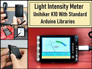 Light Meter Project - Making Dfrobot Unihiker K10 Work with Standard Arduino Libraries
The other day I received a shipment with a UNIHIKER K10 development board from DFRobot, which I rec...
Light Meter Project - Making Dfrobot Unihiker K10 Work with Standard Arduino Libraries
The other day I received a shipment with a UNIHIKER K10 development board from DFRobot, which I rec...
-
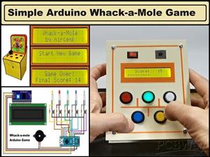 DIY Simple Arduino Whack-a-Mole Game
A "Whack-a-Mole" game is a classic arcade-style game where moles pop up randomly from holes, and th...
DIY Simple Arduino Whack-a-Mole Game
A "Whack-a-Mole" game is a classic arcade-style game where moles pop up randomly from holes, and th...
-
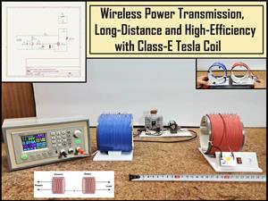 Wireless Power Transmission, Long-Distance and High-Efficiency with Class-E Tesla Coil
Wireless energy transfer also known as wireless power transmission is a method of getting useful el...
Wireless Power Transmission, Long-Distance and High-Efficiency with Class-E Tesla Coil
Wireless energy transfer also known as wireless power transmission is a method of getting useful el...
-
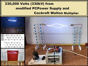 330,000 volts (330kV) from modified PC Power Supply and Cockroft Walton Multiplier
The Cockcroft-Walton voltage multiplier is a circuit configuration used to generate high DC voltage...
330,000 volts (330kV) from modified PC Power Supply and Cockroft Walton Multiplier
The Cockcroft-Walton voltage multiplier is a circuit configuration used to generate high DC voltage...
-
 Raspberry Pi Pico SSTV Decoder- Receive Images Over Radio
Slow-scan television (SSTV) is a method for transmitting and receiving still pictures over radio wav...
Raspberry Pi Pico SSTV Decoder- Receive Images Over Radio
Slow-scan television (SSTV) is a method for transmitting and receiving still pictures over radio wav...
-
 Building a Plasma Flame Generator, HFSSTC Class-E Tesla Coil
Plasma flame generator is a device that utilizes the high-frequency, high-voltage output of a Tesla...
Building a Plasma Flame Generator, HFSSTC Class-E Tesla Coil
Plasma flame generator is a device that utilizes the high-frequency, high-voltage output of a Tesla...
-
 DIY STM32 Alarm Clock with 7-Segment Display (Using Arduino IDE)
This time I will present you a classic 7 segment display alarm clock which will represent another o...
DIY STM32 Alarm Clock with 7-Segment Display (Using Arduino IDE)
This time I will present you a classic 7 segment display alarm clock which will represent another o...
-
 Arduino Breakout game on 8X8 Led Matrix with WS2812B Leds
Recently in one of my projects I presented you a simple way to make a Tetris game on an 8x8 LED dis...
Arduino Breakout game on 8X8 Led Matrix with WS2812B Leds
Recently in one of my projects I presented you a simple way to make a Tetris game on an 8x8 LED dis...
-
 How to make Simple Offline High Voltage Generator 220V to 60000V
A high voltage power supply is an electronic device that provides an electrical output at high vol...
How to make Simple Offline High Voltage Generator 220V to 60000V
A high voltage power supply is an electronic device that provides an electrical output at high vol...
-
 8-bit Space Shooter on ESP8266 & LED Matrix - DIY Arduino Gaming
Arcade games are fast-paced, simple-to-play video games and Goal is usually to get the highest score...
8-bit Space Shooter on ESP8266 & LED Matrix - DIY Arduino Gaming
Arcade games are fast-paced, simple-to-play video games and Goal is usually to get the highest score...
-
DIY Low Voltage One Tube 6J1 SW-SSB SDR Radio (Works at 3.7V)
A vacuum tube radio, also known as a valve radio, is an early type of radio receiver that uses vacu...
-
Simple & Versatile Arduino Kitchen Timer with TM1637 Display
A kitchen timer is a simple, user-friendly device that counts down a set time and alerts the user w...
-
Building an E-Paper Analog Clock with ESP32 - Full Tutorial
In several of my previous projects you could see various unusual clocks , including several in the ...
-
DIY ESP32 15 Puzzle game on TFT touch Dispaly
The "15 Puzzle" is a classic sliding puzzle that consists of a 4×4 grid with 15 numbered square til...
-
DIY Simple Sensitive Pinpointer Metal Detector
A pinpointer metal detector, often simply called a pinpointer, is a small, handheld device used to ...
-
Dynamic LED Hourglass with Sound Effects - ESP32 & 16x16 Color Matrix Tutorial
Altium 365 . Altium 365 is a cloud-based platform designed for electronics design and engineering. I...
-
Arduino 3D Printed self Balancing Cube
Self-balancing devices are electronic devices that use sensors and motors to keep themselves balanc...
-
DIY Magnet Polarity Detector - How to Identify Poles with a Hall Sensor from a PC Fan
Recently, while working on a project, I needed to determine the polarity of several permanent magne...
-
Light Meter Project - Making Dfrobot Unihiker K10 Work with Standard Arduino Libraries
The other day I received a shipment with a UNIHIKER K10 development board from DFRobot, which I rec...
-
DIY Simple Arduino Whack-a-Mole Game
A "Whack-a-Mole" game is a classic arcade-style game where moles pop up randomly from holes, and th...
-
Wireless Power Transmission, Long-Distance and High-Efficiency with Class-E Tesla Coil
Wireless energy transfer also known as wireless power transmission is a method of getting useful el...
-
330,000 volts (330kV) from modified PC Power Supply and Cockroft Walton Multiplier
The Cockcroft-Walton voltage multiplier is a circuit configuration used to generate high DC voltage...
-
-
-
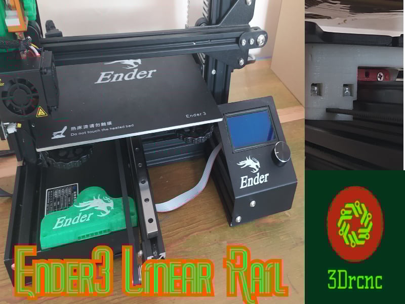
Ender 3 Linear Rail Upgrade (No modifying of existing parts)
310 0 0 -
3D Printed Snow Tires For 1/10 Scale RC Car (12mm hex)
214 0 1 -
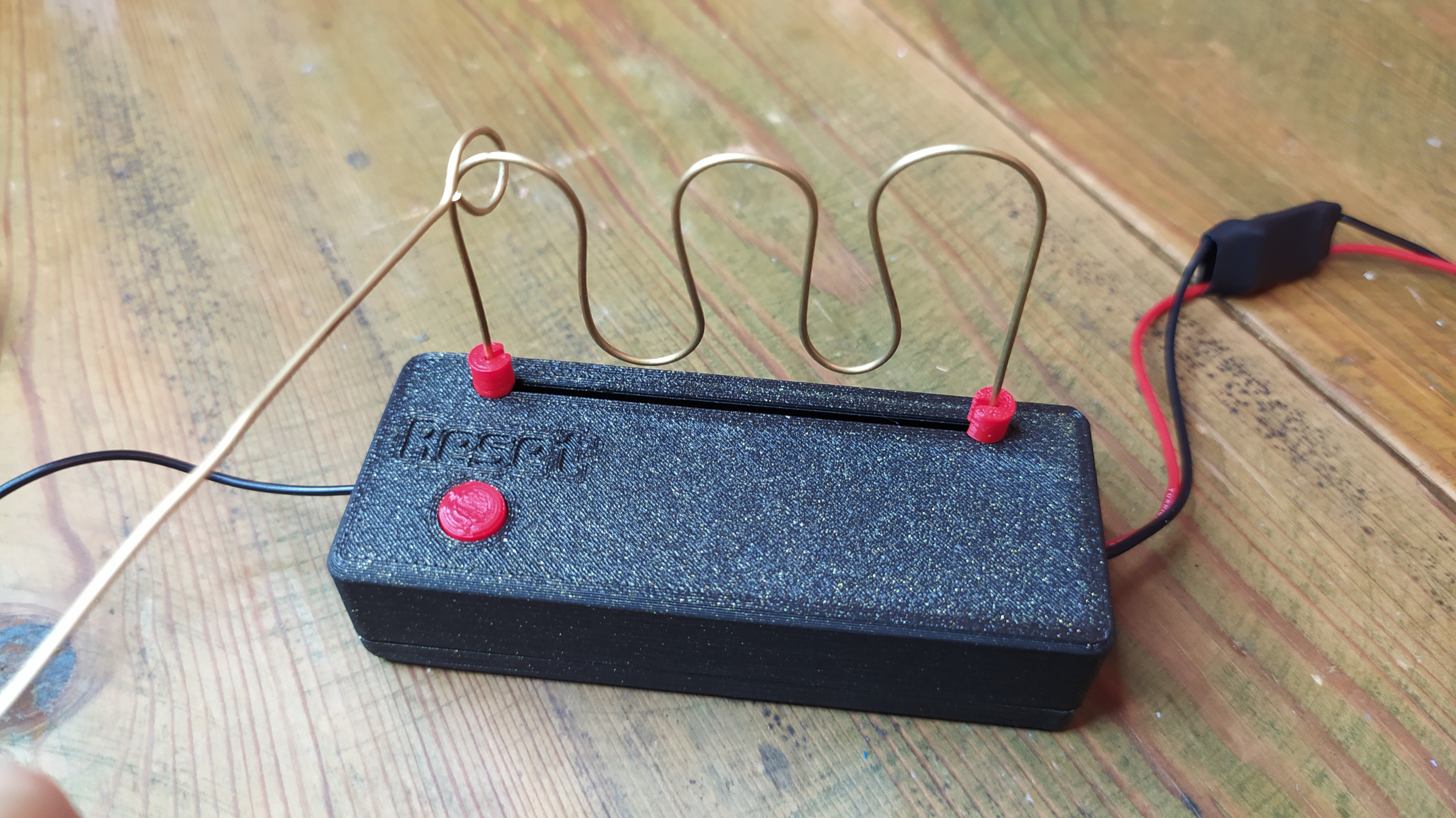
Buzz Wire Game enclosure for Futurekit FK145 soldering kit
226 0 1 -
PROJECT NEPTUNE - REV 4 - 30TH ANNIVERSARY EDITION
714 0 0