


|
|
Arduino Nano R3 |
x 1 | |
|
|
LCD display with ST7920 driver chip |
x 1 | |
|
|
Si5351 Signal Generator Module |
x 1 | |
|
|
Rotary Encoder with Push-Button |
x 1 | |
|
|
Pushbutton |
x 1 | |
|
|
Switch |
x 1 |

|
Soldering Iron Wire |
|

|
arduino IDEArduino
|
Arduino VFO Project with a Large LCD Display
A Variable Frequency Oscillator (VFO) is an electronic oscillator whose output frequency can be adjusted or varied over a specified range. It generates periodic waveforms, whose frequency can be dynamically controlled. VFOs are crucial in a wide range of applications, particularly in communications, testing, and signal processing.
In one of my previous videos I presented a way to make such a device with an ESP32 microcontroller on a color TFT display. This time I will present you a VFO which according to its characteristics is identical to the previously mentioned one, although it has an incomparably simpler code, and is made with an Arduino Nano microcontroller.
The original device that I present to you in this video is the work of Julio Cesar and all credits go to him. In fact, I made the original device more than a year ago on the SH1106 OLED display, which is larger than the SSD 1306, but even this display is relatively small and difficult to read. Therefore, I decided with my modest programming experience to rewrite the code for the ST7920 LCD Display, which is significantly larger, with a visual area of 70x40 mm.

This project is sponsored by PCBWay. They has all the services you need to create your project at the best price, whether is a scool project, or complex professional project. On PCBWay you can share your experiences, or get inspiration for your next project. They also provide completed Surface mount SMT PCB assemblY service at a best price, and ISO9001 quality control. Visit pcbway.com for more services

Since this display is not supported by the Adafruit GFX library, I used the U8G2 library in my project, which currently has support for a huge number of different display types, so by changing only one line in the code, you could use a related display.
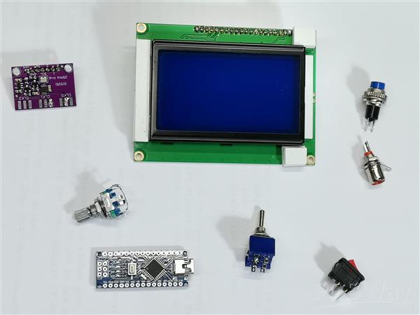
The device is really very simple to make and consists of a few components.
- Arduino nano microcontroller
- Si5351 Signal Generator module
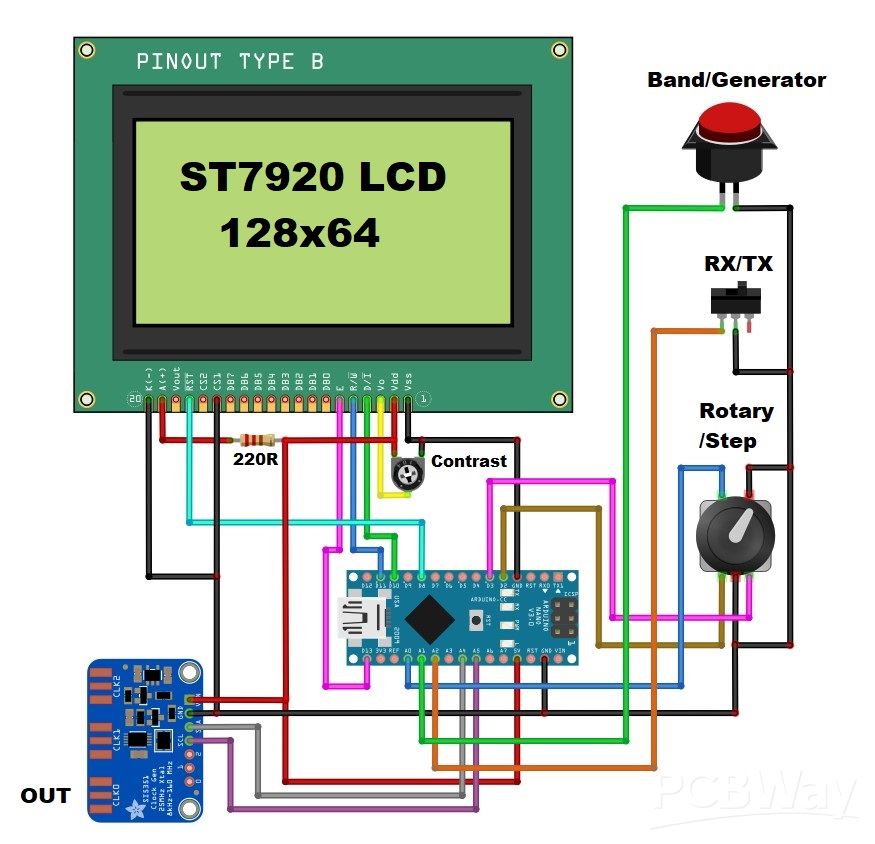
- LCD display with ST7920 driver chip
- Rotary Encoder with push button
- band selection button
- and RX-TX switch

Now let me briefly describe how the device works. Immediately after switching on, the display is initialized and then the working screen appears. The starting frequency is entered previously in the code and in this case it is the 40m amateur band. The frequency is changed with the rotary encoder. The tuning step is selected with the encoder knob and can be 1Hz, 10Hz, 1kHz, 5kHz, 10kHz and 1MHz. With this button we can select one of the 20Band Presets, as well as the Generator function mode. Operation range is from 10kHz to up to 200 MHz. In the code we can set the Intermediate Frequency (IF) offset (+ or -) for use in Superheterodyne or other type of radio receivers. It also has a selector for RX or TX mode of operation which is ideal for use in Homebrew QRP Transceivers. VFO also consist bargraph type S-meter. The signal for the S-meter is fed to the A3 analog input of the Arduino. This input has adjustable sensitivity, the gain must be adjusted in Sketch, accepting signals from 500mV to 5V (max).

A more detailed description of the method of operation can be found on the author's page. And now let's do a short test to see if the output signal corresponds to the value presented on the display. For this purpose I will use an oscilloscope. As can be seen, at lower frequencies the signal is rectangular, and with increasing the generated frequency, it gradually turns into a sinusoidal one as a result of the slow transition from low to high level and vice versa.

However, this is not a problem at all, at least in radio engineering where I most often plan to use this device. In fact, I plan for one of my next projects to be a simple Direct Conversion receiver with a VFO presented in this video.
And finally, a short conclusion. This is a cheap and easy-to-build VFO device that is almost indispensable in radio engineering, especially in DIY radio receivers. Credits to the creator of the original project, CesarSound.

#include <Wire.h>
#include <Rotary.h>
#include <si5351.h>
#include <U8g2lib.h>

// Pin definitions
#define PIN_TUNESTEP A0
#define PIN_BAND     A1
#define PIN_RX_TX    A2
#define PIN_ADC      A3
#define PIN_ROT_1    2
#define PIN_ROT_2    3
#define PIN_RST      8
#define PIN_CS       10
#define PIN_MOSI     11
#define PIN_SCK      13

// Constants
#define IF_FREQ    455
#define BAND_INIT  7
#define XT_CAL_F   33000
#define S_GAIN     303

// Frequency range limits
const uint32_t MIN_FREQ = 10000UL;      // 10 kHz
const uint32_t MAX_FREQ = 225000000UL;  // 225 MHz

// Band names stored in program memory
const char BAND_0[] PROGMEM = " GEN";
const char BAND_1[] PROGMEM = " MW";
const char BAND_2[] PROGMEM = " 160m";
const char BAND_3[] PROGMEM = " 80m";
const char BAND_4[] PROGMEM = " 60m";
const char BAND_5[] PROGMEM = " 49m";
const char BAND_6[] PROGMEM = " 40m";
const char BAND_7[] PROGMEM = " 31m";
const char BAND_8[] PROGMEM = " 25m";
const char BAND_9[] PROGMEM = " 22m";
const char BAND_10[] PROGMEM = " 20m";
const char BAND_11[] PROGMEM = " 19m";
const char BAND_12[] PROGMEM = " 16m";
const char BAND_13[] PROGMEM = " 13m";
const char BAND_14[] PROGMEM = " 11m";
const char BAND_15[] PROGMEM = " 10m";
const char BAND_16[] PROGMEM = " 6m";
const char BAND_17[] PROGMEM = " WFM";
const char BAND_18[] PROGMEM = " AIR";
const char BAND_19[] PROGMEM = " 2m";
const char BAND_20[] PROGMEM = " 1m";

const char* const BAND_NAMES[] PROGMEM = {
  BAND_0, BAND_1, BAND_2, BAND_3, BAND_4, BAND_5, BAND_6, BAND_7, BAND_8, BAND_9,
  BAND_10, BAND_11, BAND_12, BAND_13, BAND_14, BAND_15, BAND_16, BAND_17,
  BAND_18, BAND_19, BAND_20
};

// Frequency presets stored in program memory
const uint32_t FREQ_PRESETS[] PROGMEM = {
  100000UL,    // GEN
  800000UL,    // MW
  1800000UL,   // 160m
  3650000UL,   // 80m
  4985000UL,   // 60m
  6180000UL,   // 49m
  7200000UL,   // 40m
  10000000UL,  // 31m
  11780000UL,  // 25m
  13630000UL,  // 22m
  14100000UL,  // 20m
  15000000UL,  // 19m
  17655000UL,  // 16m
  21525000UL,  // 13m
  27015000UL,  // 11m
  28400000UL,  // 10m
  50000000UL,  // 6m
  100000000UL, // WFM
  130000000UL, // AIR
  144000000UL, // 2m
  220000000UL  // 1m
};

// Frequency steps
const uint32_t FREQ_STEPS[] PROGMEM = {
  1000000UL,  // 1 MHz
  1UL,        // 1 Hz
  10UL,       // 10 Hz
  1000UL,     // 1 kHz
  5000UL,     // 5 kHz
  10000UL     // 10 kHz
};

// Object initialization
U8G2_ST7920_128X64_1_SW_SPI u8g2(U8G2_R0, PIN_SCK, PIN_MOSI, PIN_CS, PIN_RST);
Rotary r = Rotary(PIN_ROT_1, PIN_ROT_2);
Si5351 si5351;

// Global variables
uint32_t freq = 7200000UL;      // Start at 7.2MHz
uint32_t freqold;
uint32_t fstep = 1000;          // Default step 1kHz
int16_t interfreq = IF_FREQ;
int16_t cal = XT_CAL_F;
uint8_t smval;
uint8_t encoder = 1;
uint8_t stp = 4;
uint8_t n = 1;
uint8_t count = BAND_INIT;
uint8_t prevCount = BAND_INIT;
uint8_t x, xo;
bool sts = 0;
bool displayOK = false;

// Function prototypes
bool setSi5351Frequency(Si5351& si5351, uint32_t freq, int16_t interfreq);
void check_inputs();
void update_display_paged();
void initializeSi5351();

// Encoder interrupt service routine
ISR(PCINT2_vect) {
  char result = r.process();
  if (result == DIR_CW) {
    if (encoder == 1) {
      uint32_t new_freq = freq + fstep;
      if (new_freq <= MAX_FREQ) {
        freq = new_freq;
        n = (n >= 42) ? 1 : n + 1;
      }
    }
  }
  else if (result == DIR_CCW) {
    if (encoder == 1) {
      uint32_t new_freq = freq;
      if (freq >= fstep) {
        new_freq = freq - fstep;
        if (new_freq >= MIN_FREQ) {
          freq = new_freq;
          n = (n <= 1) ? 42 : n - 1;
        }
      }
    }
  }
}

void setup() {
  Serial.begin(9600);
  Serial.println(F("VFO Starting..."));

  Wire.begin();

  if (!u8g2.begin()) {
    Serial.println(F("Display init failed!"));
    while (1) { delay(1000); }
  }

  // Display initialization test
  u8g2.setFont(u8g2_font_6x12_tr);
  u8g2.firstPage();
  do {
    u8g2.drawFrame(0, 0, 128, 64);
    u8g2.drawStr(20, 32, "Initializing...");
  } while (u8g2.nextPage());
  delay(1000);

  Serial.println(F("Display initialized"));
  displayOK = true;

  // Initialize pins
  pinMode(PIN_ROT_1, INPUT_PULLUP);
  pinMode(PIN_ROT_2, INPUT_PULLUP);
  pinMode(PIN_TUNESTEP, INPUT_PULLUP);
  pinMode(PIN_BAND, INPUT_PULLUP);
  pinMode(PIN_RX_TX, INPUT_PULLUP);

  // Initialize Si5351
  initializeSi5351();

  // Setup rotary encoder interrupts
  PCICR |= (1 << PCIE2);
  PCMSK2 |= (1 << PCINT18) | (1 << PCINT19);
  sei();

  // Set initial frequency
  freq = pgm_read_dword(&FREQ_PRESETS[count - 1]);

  Serial.println(F("Setup complete"));
}

void initializeSi5351() {
  Serial.println(F("Initializing Si5351..."));
  if (!si5351.init(SI5351_CRYSTAL_LOAD_8PF, 0, 0)) {
    Serial.println(F("Si5351 init failed!"));
  }
  si5351.reset();
  delay(10);
  si5351.set_correction(cal, SI5351_PLL_INPUT_XO);
  si5351.drive_strength(SI5351_CLK0, SI5351_DRIVE_8MA);
  si5351.output_enable(SI5351_CLK0, 1);
}

bool setSi5351Frequency(Si5351& si5351, uint32_t freq, int16_t interfreq) {
  // Check if frequency is within valid range
  if (freq < MIN_FREQ || freq > MAX_FREQ) {
    return false;
  }

  uint64_t output_freq = (freq + (interfreq * 1000ULL)) * 100ULL;

  // Handle GEN mode specially
  if (count == 1) {
    si5351.reset();
    delay(10);
    si5351.set_correction(cal, SI5351_PLL_INPUT_XO);
    si5351.drive_strength(SI5351_CLK0, SI5351_DRIVE_8MA);
  }

  // Set the frequency
  si5351.set_freq(output_freq, SI5351_CLK0);
  si5351.output_enable(SI5351_CLK0, 1);

  return true;
}

void loop() {
  if (!displayOK) return;

  // Process frequency changes with error handling
  if (freqold != freq) {
    if (!setSi5351Frequency(si5351, freq, interfreq)) {
      // If frequency setting fails, try to recover
      si5351.reset();
      delay(10);
      si5351.set_correction(cal, SI5351_PLL_INPUT_XO);
      si5351.drive_strength(SI5351_CLK0, SI5351_DRIVE_8MA);
      setSi5351Frequency(si5351, freq, interfreq);
    }
    freqold = freq;
  }

  // Check inputs
  check_inputs();

  // Update display
  update_display_paged();

  // Read signal meter
  smval = analogRead(PIN_ADC);
  x = constrain(map(smval, 0, S_GAIN, 1, 14), 1, 14);
}

void check_inputs() {
  if (digitalRead(PIN_TUNESTEP) == LOW) {
    stp = (stp % 6) + 1;
    fstep = pgm_read_dword(&FREQ_STEPS[stp - 1]);
    delay(300);
  }

  if (digitalRead(PIN_BAND) == LOW) {
    uint8_t newCount = (count % 21) + 1;

    // Reset Si5351 when entering or leaving GEN mode
    if (newCount == 1 || count == 1) {
      si5351.reset();
      delay(10);
      si5351.set_correction(cal, SI5351_PLL_INPUT_XO);
      si5351.drive_strength(SI5351_CLK0, SI5351_DRIVE_8MA);
      si5351.output_enable(SI5351_CLK0, 1);
    }

    count = newCount;
    freq = pgm_read_dword(&FREQ_PRESETS[count - 1]);
    prevCount = count;
    delay(300);
  }

  sts = (digitalRead(PIN_RX_TX) == LOW);
  interfreq = (sts || count == 1) ? 0 : IF_FREQ;
}

void update_display_paged() {
  u8g2.firstPage();
  do {
    // Display frequency
    char buffer[16];
    uint32_t m = freq / 1000000UL;
    uint32_t k = (freq % 1000000UL) / 1000UL;
    uint32_t h = (freq % 1000UL);

    u8g2.setFont(u8g2_font_10x20_tr);

    if (m < 1) {
      sprintf(buffer, "%03lu.%03lu", k, h);
      u8g2.drawStr(41, 17, buffer);
    } else if (m < 100) {
      sprintf(buffer, "%lu.%03lu.%03lu", m, k, h);
      u8g2.drawStr(15, 17, buffer);
    } else {
      sprintf(buffer, "%lu.%03lu.%03lu", m, k, h);
      u8g2.drawStr(15, 17, buffer);
    }

    // Draw interface elements
    u8g2.setFont(u8g2_font_6x12_tr);
    u8g2.drawHLine(0, 22, 128);
    u8g2.drawHLine(0, 45, 128);
    u8g2.drawHLine(15, 54, 67);
    u8g2.drawVLine(105, 26, 15);
    u8g2.drawVLine(87, 26, 15);
    u8g2.drawVLine(87, 50, 15);

    // Display RX/TX status
    u8g2.drawStr(91, 37, sts ? "TX" : "RX");

    // Display IF frequency
    sprintf(buffer, "IF:%d", interfreq);
    u8g2.drawStr(90, 59, buffer);

    // Display LO value
    sprintf(buffer, "LO:%d", interfreq);
    u8g2.drawStr(110, 38, buffer);

    // Display step
    u8g2.drawStr(54, 32, "STEP");
    switch(stp) {
      case 1: u8g2.drawStr(54, 42, "1MHz"); break;
      case 2: u8g2.drawStr(54, 42, "1Hz"); break;
      case 3: u8g2.drawStr(54, 42, "10Hz"); break;
      case 4: u8g2.drawStr(54, 42, "1kHz"); break;
      case 5: u8g2.drawStr(54, 42, "5kHz"); break;
      case 6: u8g2.drawStr(54, 42, "10kHz"); break;
    }

    // Display band name
    u8g2.setFont(u8g2_font_10x20_tr);
    strcpy_P(buffer, (char*)pgm_read_word(&(BAND_NAMES[count - 1])));
    u8g2.drawStr(0, 40, buffer);

    // Draw meters
    u8g2.setFont(u8g2_font_6x12_tr);
    byte y = map(n, 1, 42, 1, 14);

    u8g2.drawStr(0, 54, "TU");
    u8g2.drawBox(15 + (y-1)*5, 47, 2, 6);

    u8g2.drawStr(0, 63, "SM");
    for (byte i = 1; i <= x; i++) {
      u8g2.drawBox(15 + (i-1)*5, 57, 2, 6);
    }

  } while (u8g2.nextPage());
}
Arduino VFO Project with a Large LCD Display


- Comments(3)
- Likes(1)
More by Mirko Pavleski
-
 Arduino 3D Printed self Balancing Cube
Self-balancing devices are electronic devices that use sensors and motors to keep themselves balanc...
Arduino 3D Printed self Balancing Cube
Self-balancing devices are electronic devices that use sensors and motors to keep themselves balanc...
-
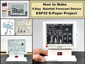 DIY 5-Day Rainfall Forecast Device - ESP32 E-Paper Project
In several of my previous projects I have presented ways to make weather stations, but this time I ...
DIY 5-Day Rainfall Forecast Device - ESP32 E-Paper Project
In several of my previous projects I have presented ways to make weather stations, but this time I ...
-
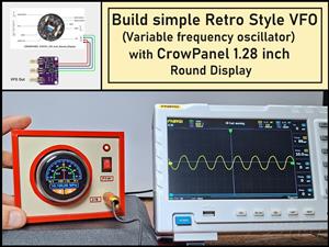 Build simple Retro Style VFO (Variable frequency oscillator) with Crowoanel 1.28 inch Round Display
Today I received a shipment with a Small round LCD display from Elecrow. The device is packed in tw...
Build simple Retro Style VFO (Variable frequency oscillator) with Crowoanel 1.28 inch Round Display
Today I received a shipment with a Small round LCD display from Elecrow. The device is packed in tw...
-
 Human vs Robot – Rock Paper Scissors with MyCobot 280 M5Stack
Today I received a package containing the few Elephant Robotics products. The shipment is well pack...
Human vs Robot – Rock Paper Scissors with MyCobot 280 M5Stack
Today I received a package containing the few Elephant Robotics products. The shipment is well pack...
-
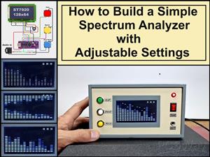 How to Build a Simple Audio Spectrum Analyzer with Adjustable Settings
An audio spectrum analyzer is an electronic device or software tool that measures and visually disp...
How to Build a Simple Audio Spectrum Analyzer with Adjustable Settings
An audio spectrum analyzer is an electronic device or software tool that measures and visually disp...
-
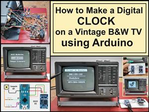 How to Make a Digital Clock on a Vintage B&W TV using Arduino
These days I accidentally came across this small retro Black and White TV with a built-in Radio, so ...
How to Make a Digital Clock on a Vintage B&W TV using Arduino
These days I accidentally came across this small retro Black and White TV with a built-in Radio, so ...
-
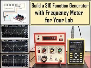 Build a $10 Function Generator with Frequency Meter for Your Lab
A function generator is a piece of electronic test equipment used to generate various types of elec...
Build a $10 Function Generator with Frequency Meter for Your Lab
A function generator is a piece of electronic test equipment used to generate various types of elec...
-
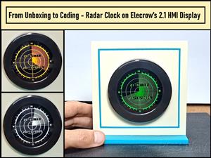 From Unboxing to Coding - Radar Clock on Elecrow’s 2.1 HMI Display
Today I received a shipment with a large round LCD display from Elecrow. The device is packed in two...
From Unboxing to Coding - Radar Clock on Elecrow’s 2.1 HMI Display
Today I received a shipment with a large round LCD display from Elecrow. The device is packed in two...
-
 Making a Retro Analog NTP Clock with Unihiker K10 - Arduino IDE Tutorial
Some time ago I presented you a way to use standard Arduino libraries on the Unihiker k10 developme...
Making a Retro Analog NTP Clock with Unihiker K10 - Arduino IDE Tutorial
Some time ago I presented you a way to use standard Arduino libraries on the Unihiker k10 developme...
-
 Build a Cheap & Easy HF Preselector - Antenna Tuner
HF antenna preselector is an electronic device connected between an HF radio antenna, and a radio r...
Build a Cheap & Easy HF Preselector - Antenna Tuner
HF antenna preselector is an electronic device connected between an HF radio antenna, and a radio r...
-
 DIY Static Charge Monitor - Electrostatic Field Detector (Arduino & TL071)
A Static Charge Monitor also known as a Static Field Meter or Electrostatic Voltmeter is a device u...
DIY Static Charge Monitor - Electrostatic Field Detector (Arduino & TL071)
A Static Charge Monitor also known as a Static Field Meter or Electrostatic Voltmeter is a device u...
-
 XHDATA D-219 Radio Short Review with complete disassembly
Some time ago I received an offer from XHDATA to be one of the first test users of their new radio m...
XHDATA D-219 Radio Short Review with complete disassembly
Some time ago I received an offer from XHDATA to be one of the first test users of their new radio m...
-
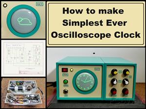 How to make Simplest ever Oscilloscope Clock
An oscilloscope clock is a unique and creative way to display the time using an oscilloscope, which...
How to make Simplest ever Oscilloscope Clock
An oscilloscope clock is a unique and creative way to display the time using an oscilloscope, which...
-
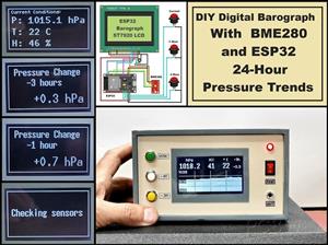 DIY Digital Barograph with BME280 and ESP32 - 24 Hour Pressure Trends
A barograph is a self-recording barometer that continuously measures and records atmospheric pressu...
DIY Digital Barograph with BME280 and ESP32 - 24 Hour Pressure Trends
A barograph is a self-recording barometer that continuously measures and records atmospheric pressu...
-
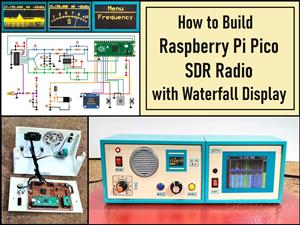 Build a Raspberry Pi Pico SDR Radio with Waterfall Display
Software-defined radio (SDR) is a radio communication system where components that have traditional...
Build a Raspberry Pi Pico SDR Radio with Waterfall Display
Software-defined radio (SDR) is a radio communication system where components that have traditional...
-
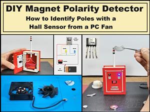 DIY Magnet Polarity Detector - How to Identify Poles with a Hall Sensor from a PC Fan
Recently, while working on a project, I needed to determine the polarity of several permanent magne...
DIY Magnet Polarity Detector - How to Identify Poles with a Hall Sensor from a PC Fan
Recently, while working on a project, I needed to determine the polarity of several permanent magne...
-
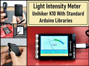 Light Meter Project - Making Dfrobot Unihiker K10 Work with Standard Arduino Libraries
The other day I received a shipment with a UNIHIKER K10 development board from DFRobot, which I rec...
Light Meter Project - Making Dfrobot Unihiker K10 Work with Standard Arduino Libraries
The other day I received a shipment with a UNIHIKER K10 development board from DFRobot, which I rec...
-
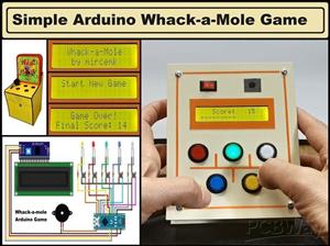 DIY Simple Arduino Whack-a-Mole Game
A "Whack-a-Mole" game is a classic arcade-style game where moles pop up randomly from holes, and th...
DIY Simple Arduino Whack-a-Mole Game
A "Whack-a-Mole" game is a classic arcade-style game where moles pop up randomly from holes, and th...
-
-
-
-
Tester for Touch Screen Digitizer without using microcontroller
322 2 2 -
Audio reactive glow LED wristband/bracelet with NFC / RFID-Tags
306 0 1 -
-
-


