
|
arduino IDEArduino
|
ESP8266-12E in Arduino Form Factor
ESP8266-12E in Arduino Form Factor
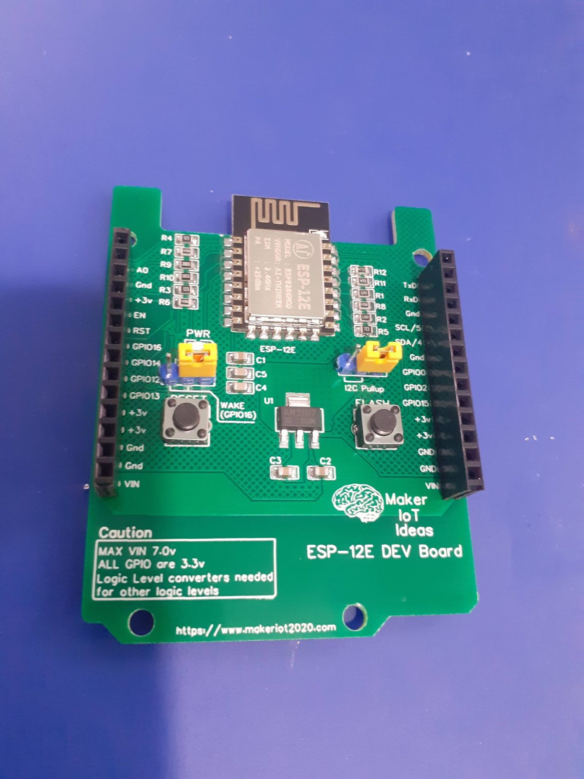
As a followup to my recent ESP32-S in Arduino Form Factor device, I decided to also produce a similar circuit board for the ESP8266-12E. Although some people mostly consider these as obsolete, I still find them extremely useful for small projects, and thus use quite a lot of them.
With their lower total pin count and similar low cost to the bigger ESP32 modules, these do force you to get quite creative with the available pins, as well as how and what you can interface.
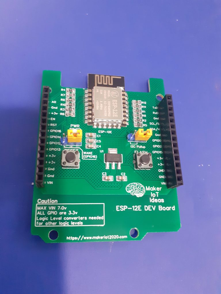 ESP8266-12E in Arduino Form Factor, with optional I2C pullups as well as Wake from sleep function on GPIO16
What is on the PCB?
For this design, I have once again tried to keep it very lean, including the absolute bare minimum supporting components needed for correct operation.
This includes pull-up and pull-down resistors on the various strapping pins, as well as some decoupling capacitors.
I also did not include a USB-to-Serial converter circuit, as these are used only once or twice, and also consume power while not being needed all the time.
As most of my devices are uploaded OTA anyway, an external stand-alone USB-to-Serial adapter is perfect to upload the initial firmware.
Jumpers to control the onboard I2C pullup-resistors, as well as the Wake-up-from-deep-sleep function on GPIO16 were also added, in addition to the Reset and Flash push-buttons to place the device into initial programming mode.
A 3.3v LDO regulator was also added, for convenience mostly, when powering the device from a bench power supply unit. The recommended voltage for this LDO would in my opinion be 7v Dc, although the datasheet states it can be up to 15v DC… In my opinion, that stresses the component a bit much though, as most of that excessive voltage is dissipated as heat.
PCB Layout – Blank board, front and back
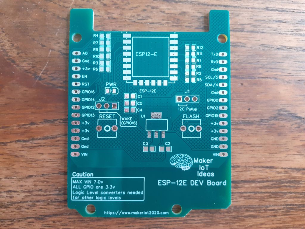 Blank ESP-12E Dev board PCB – Front
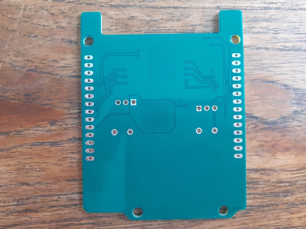 ESP-12E Dev board- Back
To try and minimise heat-related issues with the LDO regulator, I have incorporated an on-PCB heatsink for the LDO regulator, which is via-stiched together on both sides of the PCB. This type of heatsink seems to work quite well in many of my other designs, so I decided to use it here as well.
I have also made use of big copper pours on both sides of the PCB to ensure that there is a good ground plane, as well as make use of differential pairs for the routing of the UART and I2C tracks.
Schematic
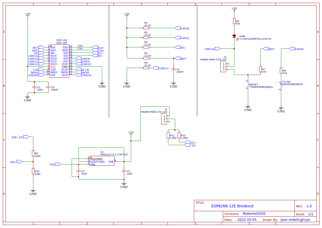 ESP-12E Dev Board Schematic
PCB Design

Manufacturing
The PCB for this project has been manufactured at PCBWay.
Please consider supporting them if you would like your own copy of this PCB, or if you have any PCB of your own that you need to have manufactured.

Some assembly pictures
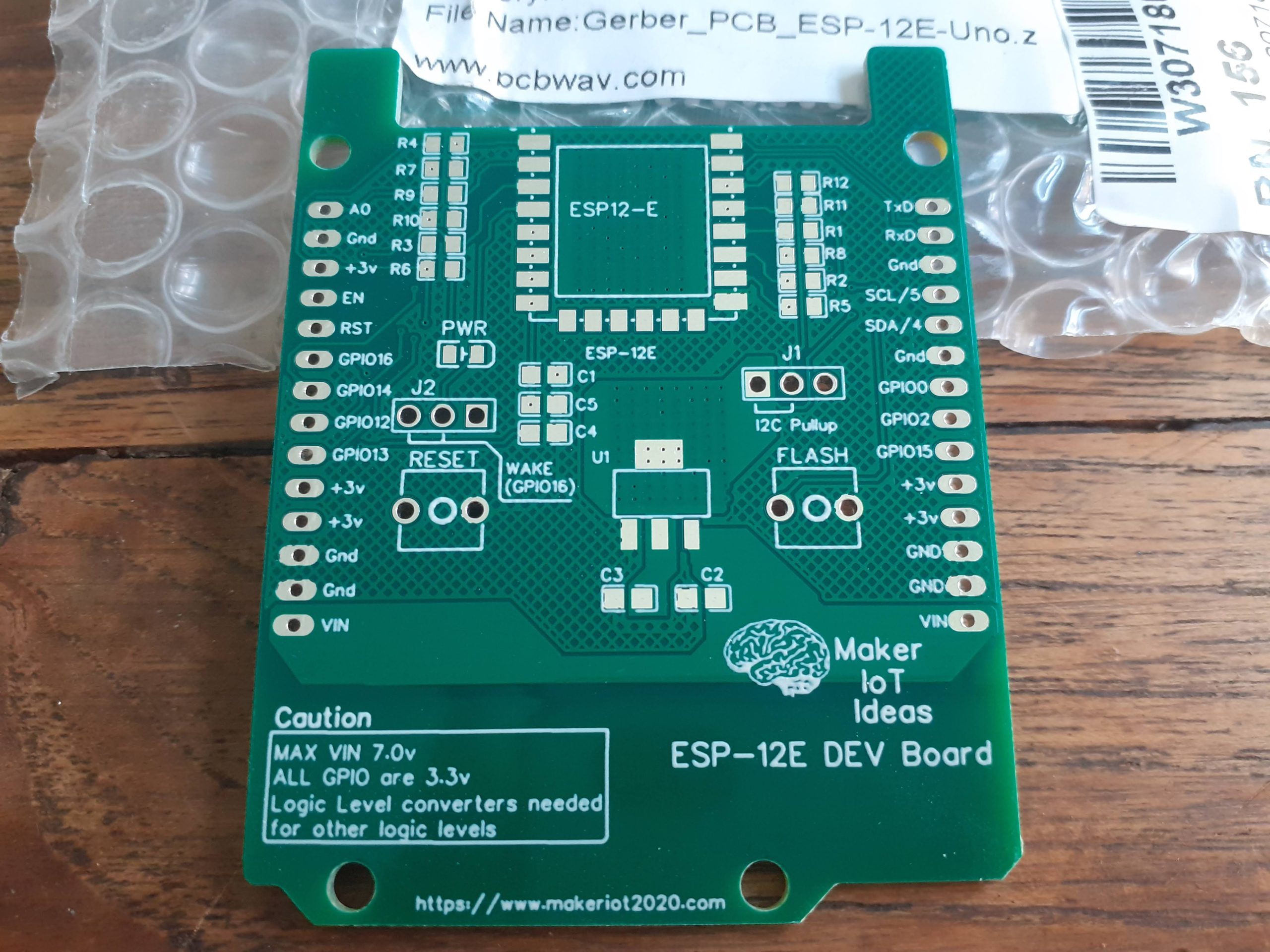 PCB fresh out of the Pacakage
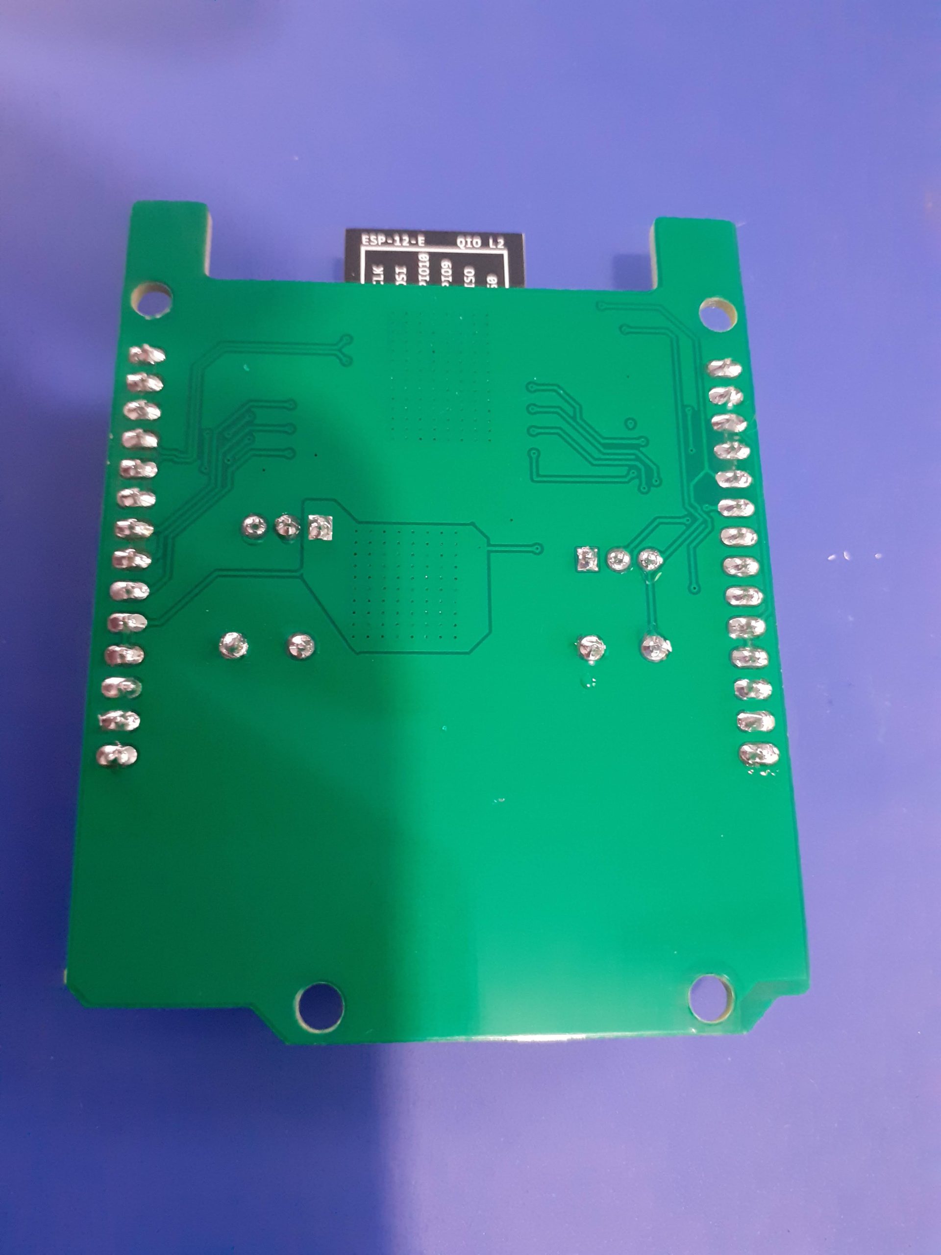 Back side of final assembly
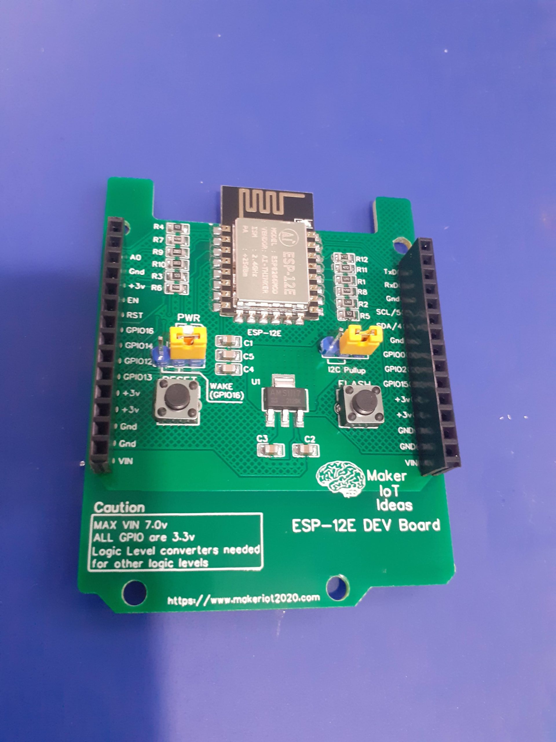 Final Assembly – front
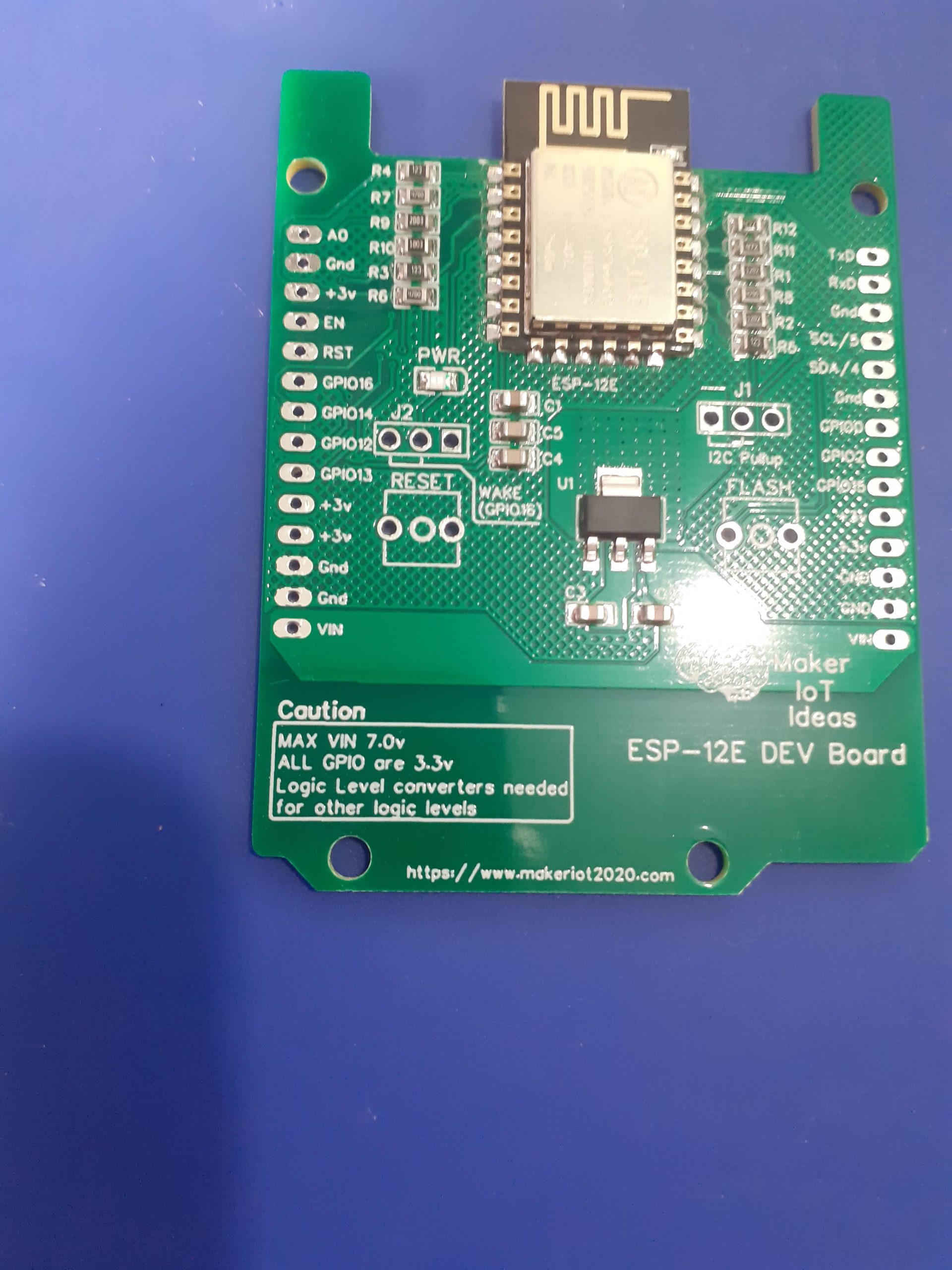 After reflowing the SMD components
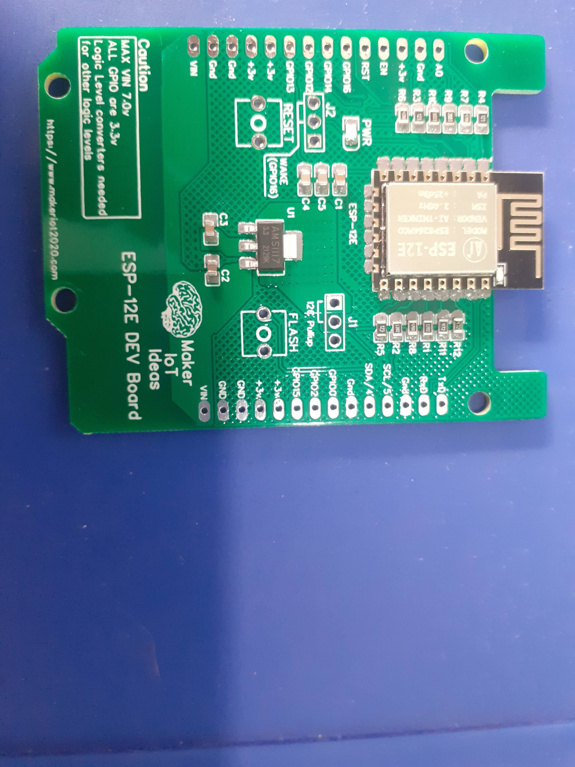 Before Reflow of SMD Components
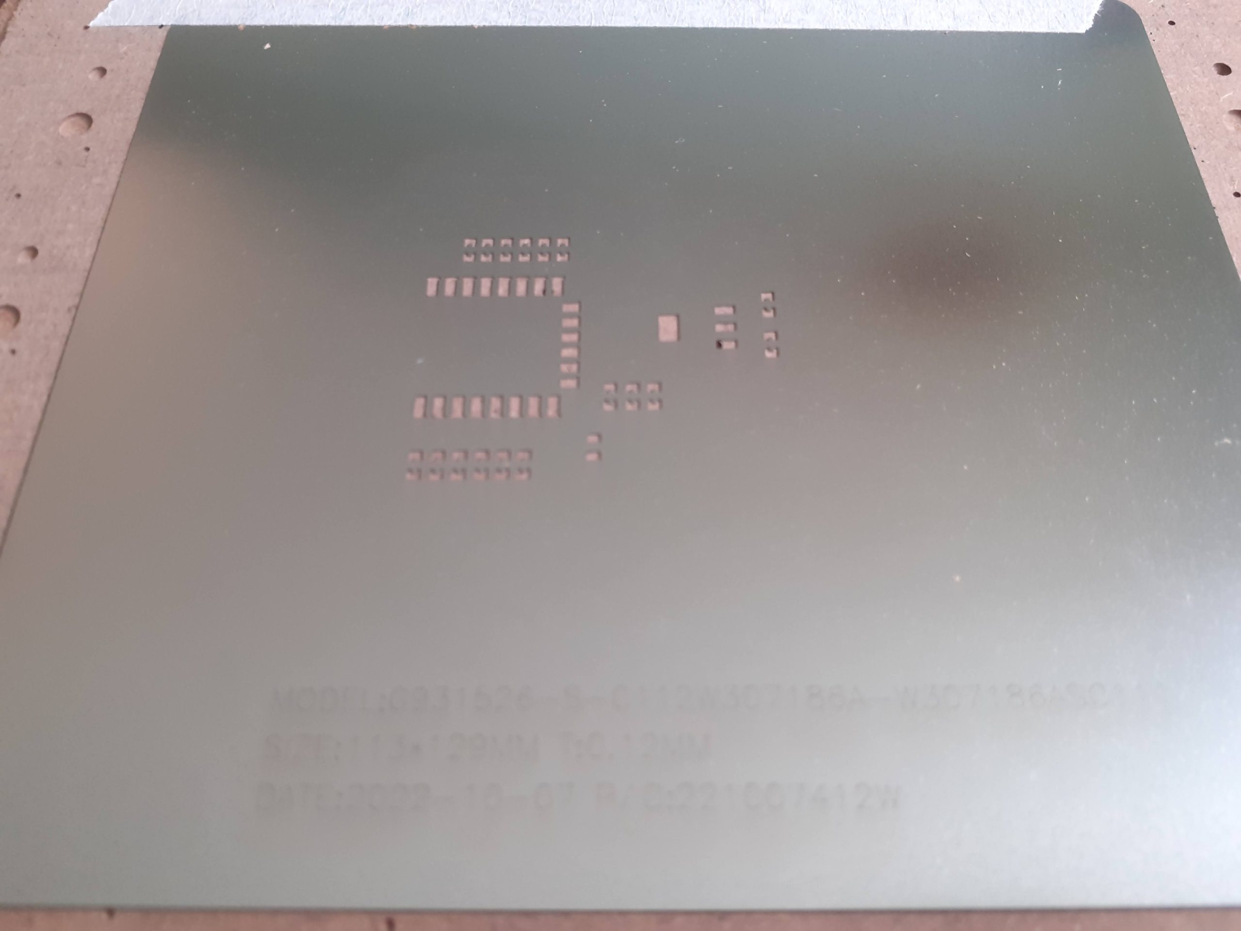 SMD Stencil to make life a bit easier
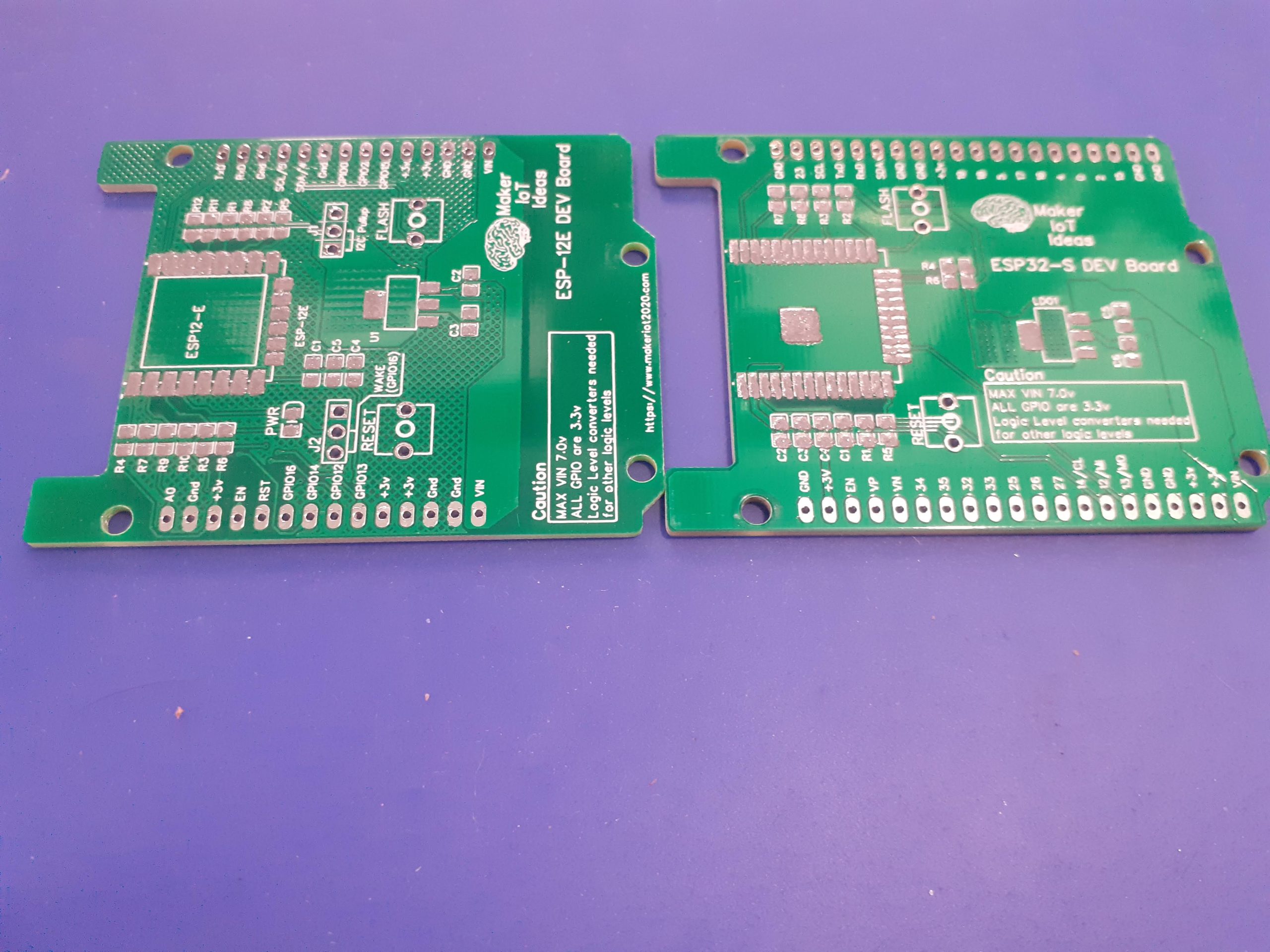 After Solderpaste application
Procedure to upload initial firmware
Due to the fact that this device does not have an onboard USB-to-UART (Serial) converter, it will be necessary to use an external device the first time that you upload firmware, or while you are using it on the bench if you do not want to use OTA…
The easiest way to do this, in my opinion, is the following:
1) Power the device from a bench power supply, set at 7V DC via the VIN and GND Pins, available on the bottom left and right of the device ( you can use either side, not both ??
2) Now connect your external USB-to-UART converter to the device, as follows:
UART Converter <-> ESP-12E Dev Board
Rx <- TxD
Tx -> RxD
Gnd — GnD
Do Not connect the power (VCC) from the USB-to-UART Converter!
Now start your Adruino IDE, or similar, and connect to the Serial monitor.
Press the reset button on the board, and watch for output in the serial monitor.
If you see output, at 115200 BPS, press end hold flash, and then reset, while still holding the flash button.
Wait a few seconds, and then upload your sketch, remembering to manually reset the board after the upload has completed.
I would recommend that you upload the Arduino OTA sketch, from the examples, and modify it to connect to your local WiFi. That way, you will be able to upload all following sketches via your local Wifi, providing that you do not remove the OTA code from the sketch.
Please see the article for coding instructions. It is assumed that you will be using Arduino IDE. The same procedure will also work for ESP-IDF, PlatformIO, or even Micropython etc, though you will have to make some minor adjustments

ESP8266-12E in Arduino Form Factor
*PCBWay community is a sharing platform. We are not responsible for any design issues and parameter issues (board thickness, surface finish, etc.) you choose.

Raspberry Pi 5 7 Inch Touch Screen IPS 1024x600 HD LCD HDMI-compatible Display for RPI 4B 3B+ OPI 5 AIDA64 PC Secondary Screen(Without Speaker)
BUY NOW
ESP32-S3 4.3inch Capacitive Touch Display Development Board, 800×480, 5-point Touch, 32-bit LX7 Dual-core Processor
BUY NOW
Raspberry Pi 5 7 Inch Touch Screen IPS 1024x600 HD LCD HDMI-compatible Display for RPI 4B 3B+ OPI 5 AIDA64 PC Secondary Screen(Without Speaker)
BUY NOW- Comments(0)
- Likes(1)
 Log in to post comments.
-
 Mark Stephany
Oct 24,2022
- 1 USER VOTES
- YOUR VOTE 0.00 0.00
- 1
- 2
- 3
- 4
- 5
- 6
- 7
- 8
- 9
- 10
- 1
- 2
- 3
- 4
- 5
- 6
- 7
- 8
- 9
- 10
- 1
- 2
- 3
- 4
- 5
- 6
- 7
- 8
- 9
- 10
- 1
- 2
- 3
- 4
- 5
- 6
- 7
- 8
- 9
- 10

-
9design
-
8usability
-
8creativity
-
9content
 More by Jean Redelinghuys MakerIoT2020
-
 RA-02 Breakout with Level converters
Breadboard and beginner-friendly RA-02 Breakout ModuleMost Makers and electronics enthusiasts may al...
-
 ATMEGA328P Module with integrated LoRa and CAN Bus
ATMEGA328P Module with integrated LoRa and CAN-BUSINTRODUCTIONIn my quest to perfect my LoRa telemet...
-
 Sx127x-Ra-02-Test-Module with ATMEGA328P-AU
SX127x LoRa/FSK/OOK Prototype Radio BoardI recently had a requirement to do some automation/telemetr...
-
 USB-ASP Programmer ATMEGA8
Build your own USB-ASP Programmer CloneBymakeriot2020 FEB 21, 2022 Arduino, ASP programmerUsing mor...
-
 ATTiny1616-LIGHT-Controller-with-CAN_B_PCB_ATTiny1616-LIGHT-Controller-with-C_2024-09-11
Assembly of the ATTiny1616 Can bus controller PCBThe Assembly of the ATTiny1616 Can Bus Controller P...
-
 ATTiny1616QFN-CAN-Remote-Neopixel-Ligh_PCB_ATTiny1616QFN-CAN-Remote-Neopixel-2024-09-11_2024-09-11
NeoPixel CAN-Bus Module with local controlAs part of my current project to add NeoPixels to the cabi...
-
 PCB_MCP23008_2023-10-08
MCP23008 BreakoutI designed this breakout to assist me during prototyping my next version of the “RP...
-
 PCB_XiaoRP2040-Mouse-REV2
Xiao RP2040 Joystick Mouse – revision 2.00Revision 1.0 of the ProjectOver the last few months, I hav...
-
 Multi Purpose IO Card
Multi-Purpose IO CardWhen we are working on a prototype, we always need access to pushbuttons, encod...
-
 Variable Voltage Power Module
Powering electronics projects are always challenging. This Variable vol...
Variable Voltage Power Module
Variable Voltage Power ModulePowering electronics projects are always challenging. This Variable vol...
-
 I2C Matrix Keypad
An I2C Matrix KeypadThe completed I2C Matrix KeypadIn a previous post this month I introduced my 4×4...
-
 ESP32-S Development Board, in "Arduino Uno" form factor
UPDATE 24/06/2023:This board now has a Hardware Revision 2.0 available. It is the same board but wit...
-
 W307186ASC94_Gerber_PCB_USB-Ports
USB Power Supply ModuleUSB Ports are quite handy to power all our day-to-day electronic devices, but...
-
 Atmega 328P based PWM controller Card
ATMega 328P Based PWM controller CardAs part of my recent ESP-12E I2C Base Board project, I designed...
-
 W307186ASC71_Gerber_PCB_ESP-Now Remote
Today we will look at the remote control unit for the Robotic Toy Car – Part 6.The project is close ...
-
 W307186ASV69_Gerber_PCB_Robot-Car-MCU-Board Prototype
In our last project, we started working on repurposing an old toy car. In this part, Robot Toy Car –...
-
 W307186ASV62_Gerber_PCB_DUAL-H-Bridge
by makeriot2020 on May 27, 2022Many of us have old toys laying around the house, they belong to ou...
-
 CAN-BUS Breakout
Breadboard Compatible CAN-BUS Breakout ModuleWhat is this:Some of us have already used the commonly ...
-
 RA-02 Breakout with Level converters
Breadboard and beginner-friendly RA-02 Breakout ModuleMost Makers and electronics enthusiasts may al...
-
 ATMEGA328P Module with integrated LoRa and CAN Bus
ATMEGA328P Module with integrated LoRa and CAN-BUSINTRODUCTIONIn my quest to perfect my LoRa telemet...
-
 Sx127x-Ra-02-Test-Module with ATMEGA328P-AU
SX127x LoRa/FSK/OOK Prototype Radio BoardI recently had a requirement to do some automation/telemetr...
-
 USB-ASP Programmer ATMEGA8
Build your own USB-ASP Programmer CloneBymakeriot2020 FEB 21, 2022 Arduino, ASP programmerUsing mor...
-
 ATTiny1616-LIGHT-Controller-with-CAN_B_PCB_ATTiny1616-LIGHT-Controller-with-C_2024-09-11
Assembly of the ATTiny1616 Can bus controller PCBThe Assembly of the ATTiny1616 Can Bus Controller P...
-
 ATTiny1616QFN-CAN-Remote-Neopixel-Ligh_PCB_ATTiny1616QFN-CAN-Remote-Neopixel-2024-09-11_2024-09-11
NeoPixel CAN-Bus Module with local controlAs part of my current project to add NeoPixels to the cabi...
-
 PCB_MCP23008_2023-10-08
MCP23008 BreakoutI designed this breakout to assist me during prototyping my next version of the “RP...
-
 PCB_XiaoRP2040-Mouse-REV2
Xiao RP2040 Joystick Mouse – revision 2.00Revision 1.0 of the ProjectOver the last few months, I hav...
-
 Multi Purpose IO Card
Multi-Purpose IO CardWhen we are working on a prototype, we always need access to pushbuttons, encod...
-
 Variable Voltage Power Module
Powering electronics projects are always challenging. This Variable vol...
Variable Voltage Power Module
Variable Voltage Power ModulePowering electronics projects are always challenging. This Variable vol...
-
 I2C Matrix Keypad
An I2C Matrix KeypadThe completed I2C Matrix KeypadIn a previous post this month I introduced my 4×4...
-
 ESP32-S Development Board, in "Arduino Uno" form factor
UPDATE 24/06/2023:This board now has a Hardware Revision 2.0 available. It is the same board but wit...
-
Commodore 64 1541-II Floppy Disk Drive C64 Power Supply Unit USB-C 5V 12V DIN connector 5.25
130 1 2 -
Easy to print simple stacking organizer with drawers
76 0 0 -
-
-
-
Modifying a Hotplate to a Reflow Solder Station
1117 1 6 -
MPL3115A2 Barometric Pressure, Altitude, and Temperature Sensor
628 0 1 -
-
Nintendo 64DD Replacement Shell
482 0 2 -
V2 Commodore AMIGA USB-C Power Sink Delivery High Efficiency Supply Triple Output 5V ±12V OLED display ATARI compatible shark 100W
1401 4 3


