


|
|
ARDUINO_NANO |
x 1 | |
|
|
I2C 16x2 Arduino LCD Display Module |
x 1 | |
|
|
button |
x 4 | |
|
|
resistors |
x 6 | |
|
|
capacitor 470µF |
x 1 |

|
arduino IDEArduino
|
|

|
Soldering Iron Kit |
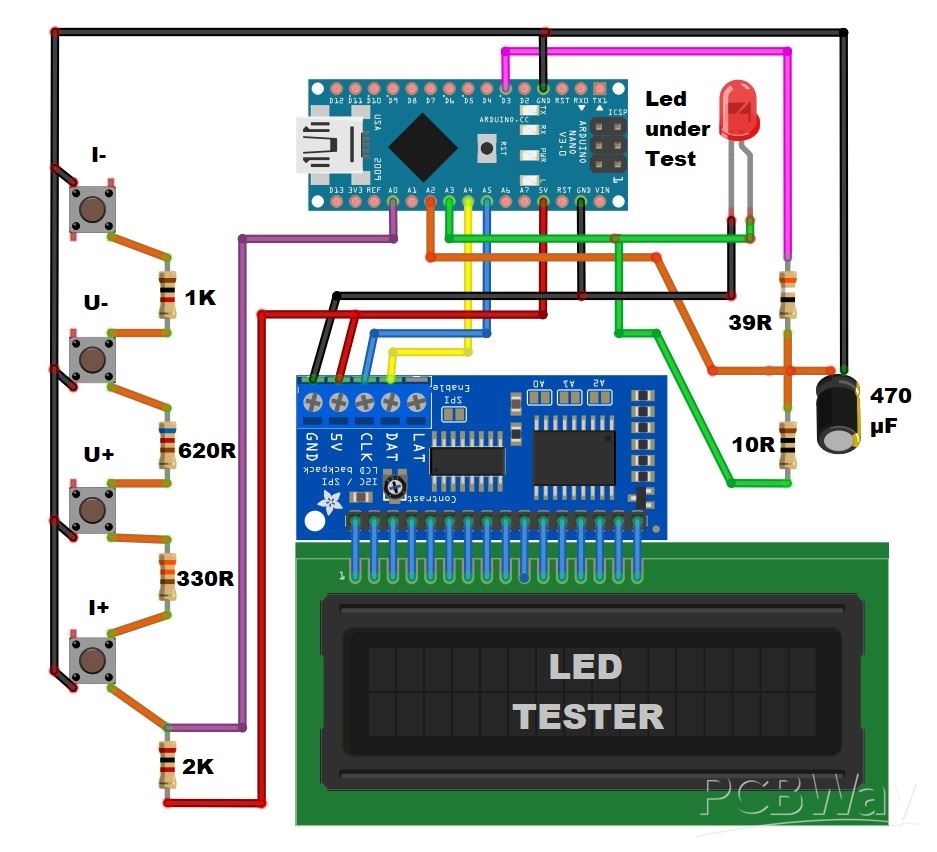
How to make Arduino LED Tester + Resistor Calculator
Light Emitting Diode as an electronic component are very often used in electronic devices. There are many different types with specific characteristics such as forward voltage and maximum current. Most often it is necessary to connect them to a higher voltage where it is necessary to connect a series resistor with a certain value.

The device described in this video is a useful tool for testing, and determining characteristics of LEDs, as well as a calculator for calculating the series resistor depending on the connected voltage.
The idea for this project was taken from Dave Cook's model, processed with an Arduino from Jaycar Electronics, and I made some changes to the code where uses an I2C LCD display, and dedicated buttons to control the device, instead of an LCD keypad shield.
The device is very simple to build, and consists of several components:
- Arduino Nano microlontroller
- 16x2 LCD Display with I2C communication protocol
- 7 Resistors
- capacitor
- and four Buttons

If you want to make a PCB for this project, or for any other electronic project, PCBway is a great choice for you. PCBway is one of the most experienced PCB manufacturing company in China in field of PCB prototype and fabrication. They provide completed PCB assembly service with worldwide free shipping , and ISO9001 quality control system. Also, on their site there is an online gerber viewer where you can upload your gerber and drill files to render your board.

And now let's see how the tester works in real conditions. When turning on the display appear previously defined values for the current and voltage to which the LED would be connected, namely a current of 10mA and a voltage of 14V. With no LED attached, it will not show a resistor value, and current value blinking.

The upper buttons can be used to set the current that will flow through the LED in the range from 1 to 20mA. These are values that in most cases cannot cause damage to the LED. The lower buttons set the value of the voltage to which the diode would be connected through a series resistor in the real circuit. This voltage can be set from 1 to 99 V, and the display then shows the required resistor value depending on the selected voltage and current. Also on the lower right part of the display appears the code of that resistor under which we can buy it in Jaycar Electronic shop. If the resistor would dissipate more than half a watt, a P flashes on the top line to let you know you might need to choose a more powerful resistor. If by mistake we connect the diode with reverse polarity, the diode remains functional, it just won't light up.

And finally a short conclusion. The device presented in this project is very simple to build, but it is a really useful instrument in the laboratory, especially due to the fact that many different types of LEDs are used nowadays. The device is embedded in a suitable box made of PVC material and lined with self-adhesive colored wallpaper

/*
Arduino LED Tester
DPIN--39R--+--10R---TESTLED---GND
           |      |         |
          470u    ATOP     ABOT
           |
          GND

 Measures LED characteristics by charging up the cap to deliver target current and find forward voltage
 From target current, we can calculate R to be used with a design supply voltage and a matching part number.
  */
#include <Wire.h>
#include <LiquidCrystal_I2C.h>
//lcd update interval
#define LCDINT 500
//key check interval
#define KEYINT 200
//pin for buttons
#define KEYPIN A0
//button constants
#define btnRIGHT  6
#define btnUP     5
#define btnDOWN   4
#define btnLEFT   3
#define btnSELECT 2
#define btnNONE   (-1)
LiquidCrystal_I2C lcd(0x27,16,2);  // set the LCD adress
//Globals for display
long itest=10;    //test current, in mA
long vset =14000;  //display voltage in mV
long vled,vrr,irr,pset;  //LED voltage, Resistor voltage, resistor current, display power
//resistors in Jaycar 1/2 W range, part nos start at RR0524 for 10R
#define RCOUNT 121
long rvals[]={10,11,12,13,15,16,18,20,22,24,27,30,33,36,39,43,47,51,56,62,68,75,82,91,100,110,120,130,150,160,180,200,220,240,270,300,330,360,390,430,470,510,560,620,680,750,820,910,1000,1100,1200,1300,1500,1600,1800,2000,2200,2400,2700,3000,3300,3600,3900,4300,4700,5100,5600,6200,6800,7500,8200,9100,10000,11000,12000,13000,15000,16000,18000,20000,22000,24000,27000,30000,33000,36000,39000,43000,47000,51000,56000,62000,68000,75000,82000,91000,100000,110000,120000,130000,150000,160000,180000,200000,220000,240000,270000,300000,330000,360000,390000,430000,470000,510000,560000,620000,680000,750000,820000,910000,1000000};
long lastlcd=0;  //time of last lcd update
long lastkey=0;  //time of last key check
int lcdflash=0;  //lcd flashing phase variable
long pdes;
long rval;      //calculated resistor value for display
long rindex;    //index of selected resistor in rvals[]
int pwmout=0;    //pwm output of current driver
int rvalid=0;    //flag if resistor value is valid
//pins for test interface
#define ATOP A2
#define ABOT A3
#define DPIN 3
#define OSAMP 16

void setup() {
  Serial.begin(9600);
// lcd.begin(16, 2);        //lcd
  lcd.begin();
  lcd.clear();
  lcd.backlight();
  pinMode(DPIN,OUTPUT);    //pwm pin
}

void loop() {
  long atop,abot,arr;      //analog sample values
  rvalid=0;                //set flag to not valid
  atop=analogoversample(ATOP,OSAMP)/OSAMP;
  abot=analogoversample(ABOT,OSAMP)/OSAMP;
  arr=atop-abot;      //this is the analog value across the 10R sense resistor
  if(arr<0){arr=0;}    //sanity check
  vled=abot*5000/1023;  //5000mV=1023 => voltage across LED
  vrr=arr*5000/1023;    //voltage across sense resistor
  irr=vrr/10;     //led and resistor current in mA (cos it's a 10R resistor)

  if(irr<itest){pwmout++;if(pwmout>255){pwmout=255;}}    //ramp up current if too low
  if(irr>itest){pwmout--;if(pwmout<0){pwmout=0;}}        //ramp down if too high
  if(irr>24){pwmout=pwmout-5;if(pwmout<0){pwmout=0;}}    //ramp down quick if too too high
  if(irr>itest*3){pwmout=pwmout-5;if(pwmout<0){pwmout=0;}}    //ramp down quick if too too high
  analogWrite(DPIN,pwmout);                              //output new PWM
  rval=(vset-vled)/itest;                                //mV/mV => ohms resistance of display resistor
  for(int i=0;i<RCOUNT;i++){                             //find next highest E24 value
    if(rvals[i]>=rval){rindex=i;rval=rvals[rindex];i=RCOUNT+1;rvalid=1;}
  }
  if(abs(irr-itest)>(itest/5)+1){rvalid=0;}              //has current settled within 20%?
  if(vled>vset){rvalid=0;}                               //if vled>vset, no valid resistor exists
  pset=0;        //work out dissipation in ballast resistor if valid)
  if(rvalid){pset=itest*itest*rval;}      //this will be in microwatts (milliamps squared)

  if(millis()-lastlcd>LCDINT){      //check if display due to be updated
    lastlcd=millis();
    dolcd();        //update display
    lcdflash=1-lcdflash;  //toggle flash variable
    }
  if(millis()-lastkey>KEYINT){    //check if keys due to be checked
    lastkey=millis();
    dobuttons();
    }
    delay(1);
}        //end of loop

void dolcd(){
  lcd.setCursor(0,0);    //first line
  //milliamps
  if(lcdflash||rvalid){        //show if correct if on flashing phase
    if(itest>9){lcd.write(((itest/10)%10)+'0');}else{lcd.write(' ');}    //blank tens if zero
    lcd.write((itest%10)+'0');
  }
  else{      //blank if not
    lcd.write(' ');lcd.write(' ');
  }
    lcd.write('m');lcd.write('A');lcd.write(' ');
  //VLED
  lcd.write(((vled/1000)%10)+'0');
  lcd.write('.');
  lcd.write(((vled/100)%10)+'0');
  lcd.write('V');lcd.write(' ');

  //actual LED current
  if(irr>9){lcd.write(((irr/10)%10)+'0');}else{lcd.write(' ');}    //blank tens if zero
  lcd.write((irr%10)+'0');
  lcd.write('m');lcd.write('A');lcd.write(' ');
  if((pset>499999)&&(lcdflash)){lcd.write('P');}else{lcd.write(' ');} //flash P if power above 1/2 watt

  lcd.setCursor(0,1);   //second line
  //
  if(vset>9999){lcd.write(((vset/10000)%10)+'0');}else{lcd.write(' ');}    //tens of vset, blank if zero
  lcd.write(((vset/1000)%10)+'0');      //units of vset
  lcd.write('V');lcd.write(' ');

  if(rvalid){
    lcdprintrval(rval);  //resistor value (4 characters)
    lcd.write(' ');
    lcdprintpartno(rindex);    //resistor part no (6 characters)
    if(pset>499999){lcd.write('!');}else{lcd.write(' ');} //show ! if power above 1/2 watt
  }else{
    lcd.write(' ');
    lcd.write('-');
    lcd.write('-');
    lcd.write('-');
    lcd.write(' ');
    lcd.write('-');
    lcd.write('-');
    lcd.write('-');
    lcd.write('-');
    lcd.write('-');
    lcd.write('-');
    lcd.write(' ');
  }
}

void lcdprintpartno(int index){
  //part number
  lcd.write('R');
  lcd.write('R');
  lcd.write('0');
  lcd.write((((index+524)/100)%10)+'0');      //part no's start at RR0524 for 10R
  lcd.write((((index+524)/10)%10)+'0');
  lcd.write((((index+524))%10)+'0');
}

void lcdprintrval(long rval){        //print a value in 10k0 format, always outputs 4 characters
  	long mult=1;
	long modval;
	if(rval>999){mult=1000;}
	if(rval>999999){mult=1000000;}
	modval=(10*rval)/mult;		//convert to final format, save a decimal place
	if(modval>999){		//nnnM
		lcd.write(((modval/1000)%10)+'0');
		lcd.write(((modval/100)%10)+'0');
		lcd.write(((modval/10)%10)+'0');
		lcdprintmult(mult);
			}else{
	if(modval>99){		//nnMn
		lcd.write(((modval/100)%10)+'0');
		lcd.write(((modval/10)%10)+'0');
		lcdprintmult(mult);
		lcd.write(((modval)%10)+'0');
			}else{	//_nMn
		lcd.write(' ');
		lcd.write(((modval/10)%10)+'0');
		lcdprintmult(mult);
		lcd.write(((modval)%10)+'0');
    }
  }
}
void lcdprintmult(long mult){      //helper function to print multiplier
	switch (mult){
	case 1:	lcd.print('R');break;
	case 1000:	lcd.print('k');break;
	case 1000000:	lcd.print('M');break;
	default:	lcd.print('?');break;
  }
}
int read_LCD_buttons(){
  int adc_key_in    = 0;
  adc_key_in = analogRead(KEYPIN);      // read the value from the sensor
  delay(5); //switch debounce delay. Increase this delay if incorrect switch selections are returned.
  int k = (analogRead(KEYPIN) - adc_key_in); //gives the button a slight range to allow for a little contact resistance noise
  if (5 < abs(k)) return btnNONE;  // double checks the keypress. If the two readings are not equal +/-k value after debounce delay, it tries again.
  // my buttons when read are centered at these valies: 0, 144, 329, 504, 741
  // we add approx 50 to those values and check to see if we are close
  if (adc_key_in > 1000) return btnNONE; // We make this the 1st option for speed reasons since it will be the most likely result
  if (adc_key_in < 50)   return btnRIGHT;
  if (adc_key_in < 195)  return btnUP;
  if (adc_key_in < 380)  return btnDOWN;
  if (adc_key_in < 555)  return btnLEFT;
  if (adc_key_in < 790)  return btnSELECT;
  return btnNONE;  // when all others fail, return this...

}
void dobuttons(){      //updates variables. debounces by only sampling at intervals
    int key;
    key = read_LCD_buttons();
    if(key==btnLEFT){itest=itest-1;if(itest<1){itest=1;}}
    if(key==btnRIGHT){itest=itest+1;if(itest>20){itest=20;}}
    if(key==btnUP){vset=vset+1000;if(vset>99000){vset=99000;}}
    if(key==btnDOWN){vset=vset-1000;if(vset<0){vset=0;}}
}
long analogoversample(int pin,int samples){      //read pin samples times and return sum
  long n=0;
  for(int i=0;i<samples;i++){
    n=n+analogRead(pin);
  }
  return n;
}
How to make Arduino LED Tester + Resistor Calculator


- Comments(0)
- Likes(0)
More by Mirko Pavleski
-
 Arduino 3D Printed self Balancing Cube
Self-balancing devices are electronic devices that use sensors and motors to keep themselves balanc...
Arduino 3D Printed self Balancing Cube
Self-balancing devices are electronic devices that use sensors and motors to keep themselves balanc...
-
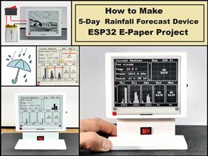 DIY 5-Day Rainfall Forecast Device - ESP32 E-Paper Project
In several of my previous projects I have presented ways to make weather stations, but this time I ...
DIY 5-Day Rainfall Forecast Device - ESP32 E-Paper Project
In several of my previous projects I have presented ways to make weather stations, but this time I ...
-
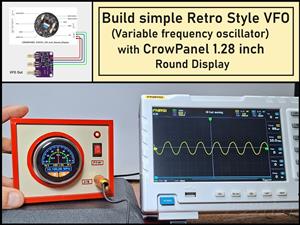 Build simple Retro Style VFO (Variable frequency oscillator) with Crowoanel 1.28 inch Round Display
Today I received a shipment with a Small round LCD display from Elecrow. The device is packed in tw...
Build simple Retro Style VFO (Variable frequency oscillator) with Crowoanel 1.28 inch Round Display
Today I received a shipment with a Small round LCD display from Elecrow. The device is packed in tw...
-
 Human vs Robot – Rock Paper Scissors with MyCobot 280 M5Stack
Today I received a package containing the few Elephant Robotics products. The shipment is well pack...
Human vs Robot – Rock Paper Scissors with MyCobot 280 M5Stack
Today I received a package containing the few Elephant Robotics products. The shipment is well pack...
-
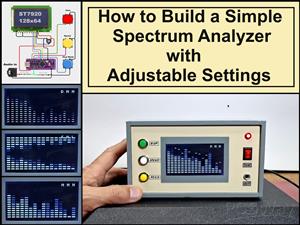 How to Build a Simple Audio Spectrum Analyzer with Adjustable Settings
An audio spectrum analyzer is an electronic device or software tool that measures and visually disp...
How to Build a Simple Audio Spectrum Analyzer with Adjustable Settings
An audio spectrum analyzer is an electronic device or software tool that measures and visually disp...
-
 How to Make a Digital Clock on a Vintage B&W TV using Arduino
These days I accidentally came across this small retro Black and White TV with a built-in Radio, so ...
How to Make a Digital Clock on a Vintage B&W TV using Arduino
These days I accidentally came across this small retro Black and White TV with a built-in Radio, so ...
-
 Build a $10 Function Generator with Frequency Meter for Your Lab
A function generator is a piece of electronic test equipment used to generate various types of elec...
Build a $10 Function Generator with Frequency Meter for Your Lab
A function generator is a piece of electronic test equipment used to generate various types of elec...
-
 From Unboxing to Coding - Radar Clock on Elecrow’s 2.1 HMI Display
Today I received a shipment with a large round LCD display from Elecrow. The device is packed in two...
From Unboxing to Coding - Radar Clock on Elecrow’s 2.1 HMI Display
Today I received a shipment with a large round LCD display from Elecrow. The device is packed in two...
-
 Making a Retro Analog NTP Clock with Unihiker K10 - Arduino IDE Tutorial
Some time ago I presented you a way to use standard Arduino libraries on the Unihiker k10 developme...
Making a Retro Analog NTP Clock with Unihiker K10 - Arduino IDE Tutorial
Some time ago I presented you a way to use standard Arduino libraries on the Unihiker k10 developme...
-
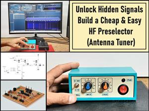 Build a Cheap & Easy HF Preselector - Antenna Tuner
HF antenna preselector is an electronic device connected between an HF radio antenna, and a radio r...
Build a Cheap & Easy HF Preselector - Antenna Tuner
HF antenna preselector is an electronic device connected between an HF radio antenna, and a radio r...
-
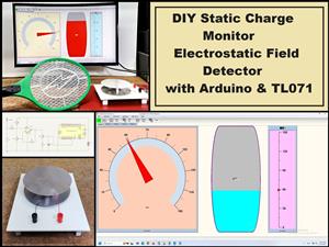 DIY Static Charge Monitor - Electrostatic Field Detector (Arduino & TL071)
A Static Charge Monitor also known as a Static Field Meter or Electrostatic Voltmeter is a device u...
DIY Static Charge Monitor - Electrostatic Field Detector (Arduino & TL071)
A Static Charge Monitor also known as a Static Field Meter or Electrostatic Voltmeter is a device u...
-
 XHDATA D-219 Radio Short Review with complete disassembly
Some time ago I received an offer from XHDATA to be one of the first test users of their new radio m...
XHDATA D-219 Radio Short Review with complete disassembly
Some time ago I received an offer from XHDATA to be one of the first test users of their new radio m...
-
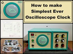 How to make Simplest ever Oscilloscope Clock
An oscilloscope clock is a unique and creative way to display the time using an oscilloscope, which...
How to make Simplest ever Oscilloscope Clock
An oscilloscope clock is a unique and creative way to display the time using an oscilloscope, which...
-
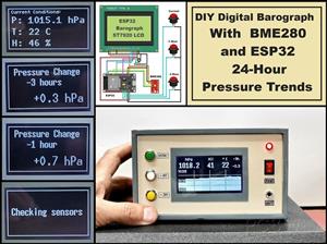 DIY Digital Barograph with BME280 and ESP32 - 24 Hour Pressure Trends
A barograph is a self-recording barometer that continuously measures and records atmospheric pressu...
DIY Digital Barograph with BME280 and ESP32 - 24 Hour Pressure Trends
A barograph is a self-recording barometer that continuously measures and records atmospheric pressu...
-
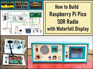 Build a Raspberry Pi Pico SDR Radio with Waterfall Display
Software-defined radio (SDR) is a radio communication system where components that have traditional...
Build a Raspberry Pi Pico SDR Radio with Waterfall Display
Software-defined radio (SDR) is a radio communication system where components that have traditional...
-
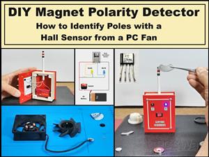 DIY Magnet Polarity Detector - How to Identify Poles with a Hall Sensor from a PC Fan
Recently, while working on a project, I needed to determine the polarity of several permanent magne...
DIY Magnet Polarity Detector - How to Identify Poles with a Hall Sensor from a PC Fan
Recently, while working on a project, I needed to determine the polarity of several permanent magne...
-
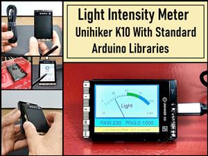 Light Meter Project - Making Dfrobot Unihiker K10 Work with Standard Arduino Libraries
The other day I received a shipment with a UNIHIKER K10 development board from DFRobot, which I rec...
Light Meter Project - Making Dfrobot Unihiker K10 Work with Standard Arduino Libraries
The other day I received a shipment with a UNIHIKER K10 development board from DFRobot, which I rec...
-
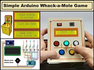 DIY Simple Arduino Whack-a-Mole Game
A "Whack-a-Mole" game is a classic arcade-style game where moles pop up randomly from holes, and th...
DIY Simple Arduino Whack-a-Mole Game
A "Whack-a-Mole" game is a classic arcade-style game where moles pop up randomly from holes, and th...
-
-
-
-
Tester for Touch Screen Digitizer without using microcontroller
321 2 2 -
Audio reactive glow LED wristband/bracelet with NFC / RFID-Tags
304 0 1 -
-
-


