Multipurpose UART/UPDI Programmer with ESP Autoflash/Reset Capability

USB-to-Serial converters are some of the most used modules on my bench. I have quite a few of them, most of them are the cheap online type that can be had for a few dollars.
As part of my new project, where I am seriously looking for an alternative chip to replace the ATMEGA328, which has become almost impossible to get, and super expensive when you do get it, I needed to get hold of a UPDI programmer.
There are many available online, from cheap to more expensive, but I wanted to build my own, as it did not seem too difficult to do.
As another part of my daily tasks, I also use a lot of ESP-type chips, which have a particular procedure to upload code via an external serial adapter.
The idea was thus to design a USB UART module that has multiple purposes, as well as being easy and cheap to assemble.
Be able to program ATMEGA328 Chips via Serial
Be able to be used as a standard USB-to-UART adapter
Be a UPDI programmer
Have a selectable target voltage between 3.3v and 5v
Have all modem signals (RTS, CTS, DSR, DTR) broken out.
Be able to auto-flash and reset an ESP32 or ESP8266 device, or similar
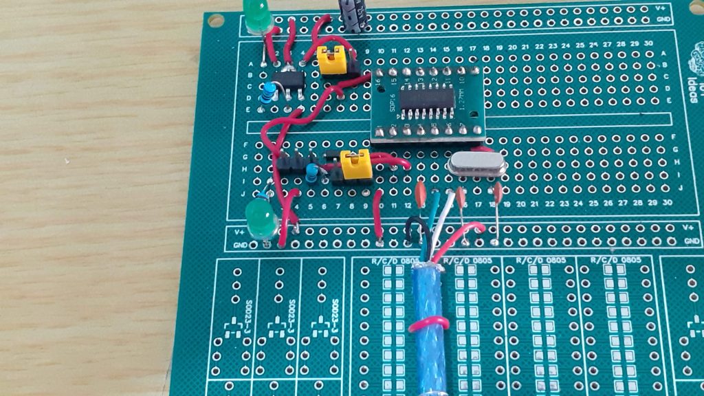
 Breadboard Prototype Multipurpose USB-to-UART/UPDI Programmer
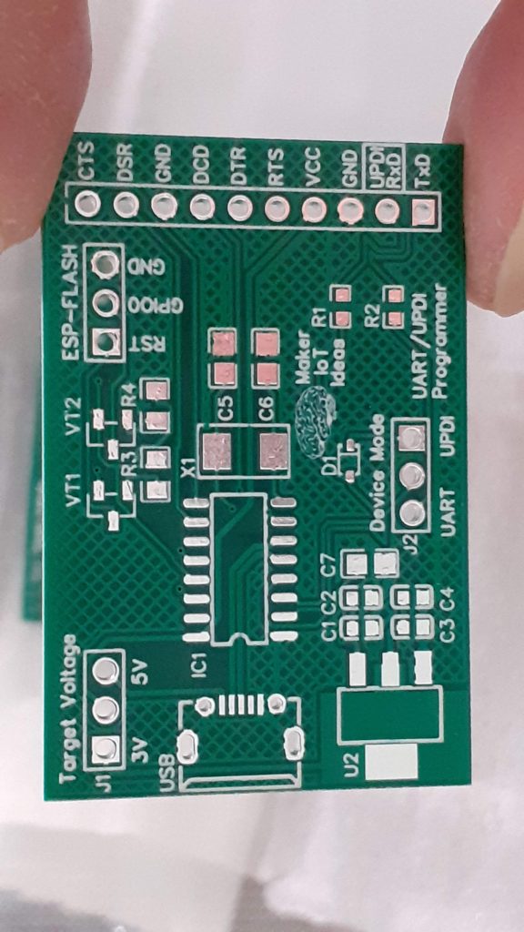
What is on the PCB?
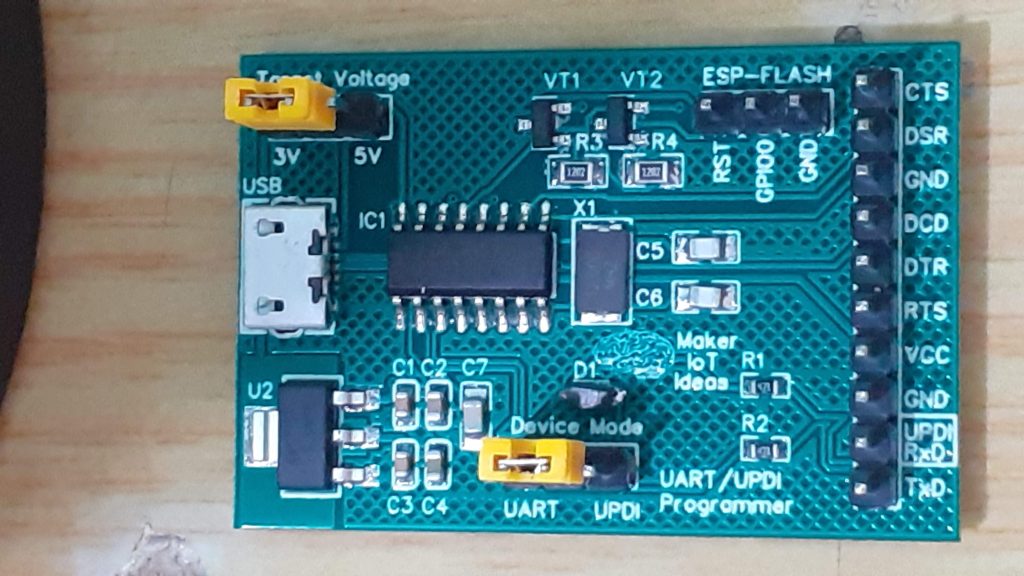
The PCB is powered by the PC USB port. The target device voltage is selectable between 3.3v and 5v. The device mode can be changed from UART to UPDI mode with a jumper. An additional header specifically for ESP32/ESP8266 devices is provided, giving access to the FLASH and reset signals for the ESP device.
The USB to serial conversion is taken care of by a CH340G Chip, which provides all the relevant modem signals as well.
All signals, with the exception of the "RING" signal, are broken out onto the main header.
Note that there are NO status or POWER LEDs on the board. This was on purpose, as these sometimes interfere with the UPDI programming mode.

Prototype PCB - Assembled
 PCB - Top
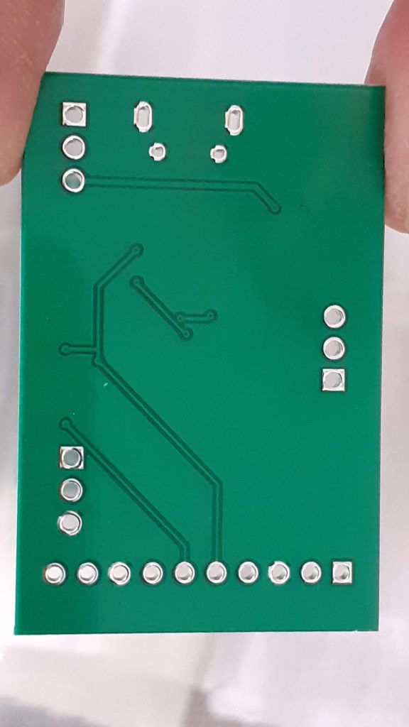
 PCB - Bottom
Connecting to different devices
ESP32 or ESP8266 Devices
When in UART mode, the device can be used to upload code to an ESP32/ESP8266 automatically, similar to a standard dev board, without requiring you to press and flash and reset buttons.
This is achieved by connecting the device as follows:
UART MODULE SET to 3v
UART VCC to ESP 3v
UART GND to ESP GND
UART RX to ESP TX
UART TX to ESP RX
(Connections for Auto Upload/Reset)
UART RST ( on ESP-Flash Header) to ESP RST
UART GPIO0 ( on ESP-Flash Header) to ESP GPIO0
It will now be possible to flash and auto reset the connected ESP device from the Arduino IDE, and possibly others as well...
Arduino (Atmega 328P)
In the current version of the prototype, you have to connect it as follows:
UART Target voltage set to 3v or 5v depending on what type of board you are uploading
UART Tx to Arduino Rx
UART Rx to Arduino Tx
UART VCC to Arduino 3v or 5v ( depending on the target voltage required by the board you are flashing)
UART GND to Arduino GND
To allow for auto flash/reset on the Arduino, a 100nf capacitor is required between the UART DTR line and the Arduino Reset pin. This capacitor has NOT yet been fitted onto the PCB, as I usually use ICSP to upload these. Future versions of the PCB shall have this included.
ATMEGA4808/4809 and or ATTiny with UPDI Interface
This device is currently an LV-only UPDI programmer. Connections are as follows:
Set Target voltage on J1 of the UART/UPDI programmer.
Set The Device mode on J2 to UPDI mode
Connect VCC and GND from the Programmer to the target chip/board
Connect Programmer UPDI pin( shared with RxD) to Target UPDI pin.
General use UART for use as Serial monitor/Terminal
Set target voltage on J1
Set device mode to UART on J2
Connect VCC, GND from UART to the target device,
UART Tx to Target Rx
Uart Rx to Target Tx
Optionally connect required modem signals, RTS, CTS, DTR, and DSR as needed

Multipurpose UART/UPDI Programmer with ESP Autoflash/Reset Capability
*PCBWay community is a sharing platform. We are not responsible for any design issues and parameter issues (board thickness, surface finish, etc.) you choose.

Raspberry Pi 5 7 Inch Touch Screen IPS 1024x600 HD LCD HDMI-compatible Display for RPI 4B 3B+ OPI 5 AIDA64 PC Secondary Screen(Without Speaker)
BUY NOW
ESP32-S3 4.3inch Capacitive Touch Display Development Board, 800×480, 5-point Touch, 32-bit LX7 Dual-core Processor
BUY NOW
Raspberry Pi 5 7 Inch Touch Screen IPS 1024x600 HD LCD HDMI-compatible Display for RPI 4B 3B+ OPI 5 AIDA64 PC Secondary Screen(Without Speaker)
BUY NOW- Comments(0)
- Likes(0)
 Log in to post comments.
- 1 USER VOTES
- YOUR VOTE 0.00 0.00
- 1
- 2
- 3
- 4
- 5
- 6
- 7
- 8
- 9
- 10
- 1
- 2
- 3
- 4
- 5
- 6
- 7
- 8
- 9
- 10
- 1
- 2
- 3
- 4
- 5
- 6
- 7
- 8
- 9
- 10
- 1
- 2
- 3
- 4
- 5
- 6
- 7
- 8
- 9
- 10
-
10design
-
10usability
-
10creativity
-
10content
 More by Jean Redelinghuys MakerIoT2020
-
 RA-02 Breakout with Level converters
Breadboard and beginner-friendly RA-02 Breakout ModuleMost Makers and electronics enthusiasts may al...
-
 ATMEGA328P Module with integrated LoRa and CAN Bus
ATMEGA328P Module with integrated LoRa and CAN-BUSINTRODUCTIONIn my quest to perfect my LoRa telemet...
-
 Sx127x-Ra-02-Test-Module with ATMEGA328P-AU
SX127x LoRa/FSK/OOK Prototype Radio BoardI recently had a requirement to do some automation/telemetr...
-
 USB-ASP Programmer ATMEGA8
Build your own USB-ASP Programmer CloneBymakeriot2020 FEB 21, 2022 Arduino, ASP programmerUsing mor...
-
 ATTiny1616-LIGHT-Controller-with-CAN_B_PCB_ATTiny1616-LIGHT-Controller-with-C_2024-09-11
Assembly of the ATTiny1616 Can bus controller PCBThe Assembly of the ATTiny1616 Can Bus Controller P...
-
 ATTiny1616QFN-CAN-Remote-Neopixel-Ligh_PCB_ATTiny1616QFN-CAN-Remote-Neopixel-2024-09-11_2024-09-11
NeoPixel CAN-Bus Module with local controlAs part of my current project to add NeoPixels to the cabi...
-
 PCB_MCP23008_2023-10-08
MCP23008 BreakoutI designed this breakout to assist me during prototyping my next version of the “RP...
-
 PCB_XiaoRP2040-Mouse-REV2
Xiao RP2040 Joystick Mouse – revision 2.00Revision 1.0 of the ProjectOver the last few months, I hav...
-
 Multi Purpose IO Card
Multi-Purpose IO CardWhen we are working on a prototype, we always need access to pushbuttons, encod...
-
 Variable Voltage Power Module
Powering electronics projects are always challenging. This Variable vol...
Variable Voltage Power Module
Variable Voltage Power ModulePowering electronics projects are always challenging. This Variable vol...
-
 I2C Matrix Keypad
An I2C Matrix KeypadThe completed I2C Matrix KeypadIn a previous post this month I introduced my 4×4...
-
 ESP32-S Development Board, in "Arduino Uno" form factor
UPDATE 24/06/2023:This board now has a Hardware Revision 2.0 available. It is the same board but wit...
-
 W307186ASC94_Gerber_PCB_USB-Ports
USB Power Supply ModuleUSB Ports are quite handy to power all our day-to-day electronic devices, but...
-
 Atmega 328P based PWM controller Card
ATMega 328P Based PWM controller CardAs part of my recent ESP-12E I2C Base Board project, I designed...
-
 W307186ASC71_Gerber_PCB_ESP-Now Remote
Today we will look at the remote control unit for the Robotic Toy Car – Part 6.The project is close ...
-
 W307186ASV69_Gerber_PCB_Robot-Car-MCU-Board Prototype
In our last project, we started working on repurposing an old toy car. In this part, Robot Toy Car –...
-
 W307186ASV62_Gerber_PCB_DUAL-H-Bridge
by makeriot2020 on May 27, 2022Many of us have old toys laying around the house, they belong to ou...
-
 CAN-BUS Breakout
Breadboard Compatible CAN-BUS Breakout ModuleWhat is this:Some of us have already used the commonly ...
-
 RA-02 Breakout with Level converters
Breadboard and beginner-friendly RA-02 Breakout ModuleMost Makers and electronics enthusiasts may al...
-
 ATMEGA328P Module with integrated LoRa and CAN Bus
ATMEGA328P Module with integrated LoRa and CAN-BUSINTRODUCTIONIn my quest to perfect my LoRa telemet...
-
 Sx127x-Ra-02-Test-Module with ATMEGA328P-AU
SX127x LoRa/FSK/OOK Prototype Radio BoardI recently had a requirement to do some automation/telemetr...
-
 USB-ASP Programmer ATMEGA8
Build your own USB-ASP Programmer CloneBymakeriot2020 FEB 21, 2022 Arduino, ASP programmerUsing mor...
-
 ATTiny1616-LIGHT-Controller-with-CAN_B_PCB_ATTiny1616-LIGHT-Controller-with-C_2024-09-11
Assembly of the ATTiny1616 Can bus controller PCBThe Assembly of the ATTiny1616 Can Bus Controller P...
-
 ATTiny1616QFN-CAN-Remote-Neopixel-Ligh_PCB_ATTiny1616QFN-CAN-Remote-Neopixel-2024-09-11_2024-09-11
NeoPixel CAN-Bus Module with local controlAs part of my current project to add NeoPixels to the cabi...
-
 PCB_MCP23008_2023-10-08
MCP23008 BreakoutI designed this breakout to assist me during prototyping my next version of the “RP...
-
 PCB_XiaoRP2040-Mouse-REV2
Xiao RP2040 Joystick Mouse – revision 2.00Revision 1.0 of the ProjectOver the last few months, I hav...
-
 Multi Purpose IO Card
Multi-Purpose IO CardWhen we are working on a prototype, we always need access to pushbuttons, encod...
-
 Variable Voltage Power Module
Powering electronics projects are always challenging. This Variable vol...
Variable Voltage Power Module
Variable Voltage Power ModulePowering electronics projects are always challenging. This Variable vol...
-
 I2C Matrix Keypad
An I2C Matrix KeypadThe completed I2C Matrix KeypadIn a previous post this month I introduced my 4×4...
-
 ESP32-S Development Board, in "Arduino Uno" form factor
UPDATE 24/06/2023:This board now has a Hardware Revision 2.0 available. It is the same board but wit...
-
Modifying a Hotplate to a Reflow Solder Station
91 0 1 -
MPL3115A2 Barometric Pressure, Altitude, and Temperature Sensor
89 0 1 -
-
Nintendo 64DD Replacement Shell
166 0 1 -
V2 Commodore AMIGA USB-C Power Sink Delivery High Efficiency Supply Triple Output 5V ±12V OLED display ATARI compatible shark 100W
325 4 1 -
How to measure weight with Load Cell and HX711
396 0 3 -
-
Instrumentation Input, high impedance with 16 bit 1MSPS ADC for SPI
515 0 0


