PCB_PWM-Fan-Controller-with-RE
Last month I spent quite a lot of time on expansion modules for use with the ESP-12E I2C Base Card. While the system worked exceptionally well as a prototyping and firmware testing platform ( as originally intended ), I immediately saw that the physical size of everything ( base board, with the cards) would be a problem inside any enclosure, when used with a real-world project.
At the same time, I have an ongoing need to design and manufacture a device for a friend, that will have very limited space inside the enclosure due to other essential components.
I have thus decided to combine the functionality of two of the IO Expander cards into a more compact design, on a single PCB ( Which I plan to use to power and control an Air Assist blower on my desktop CNC/Laser cutter, as well as function as a next step prototype for my other project.
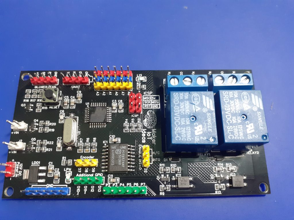
The PCB
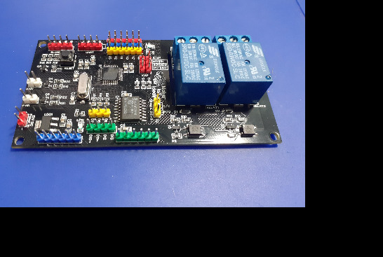
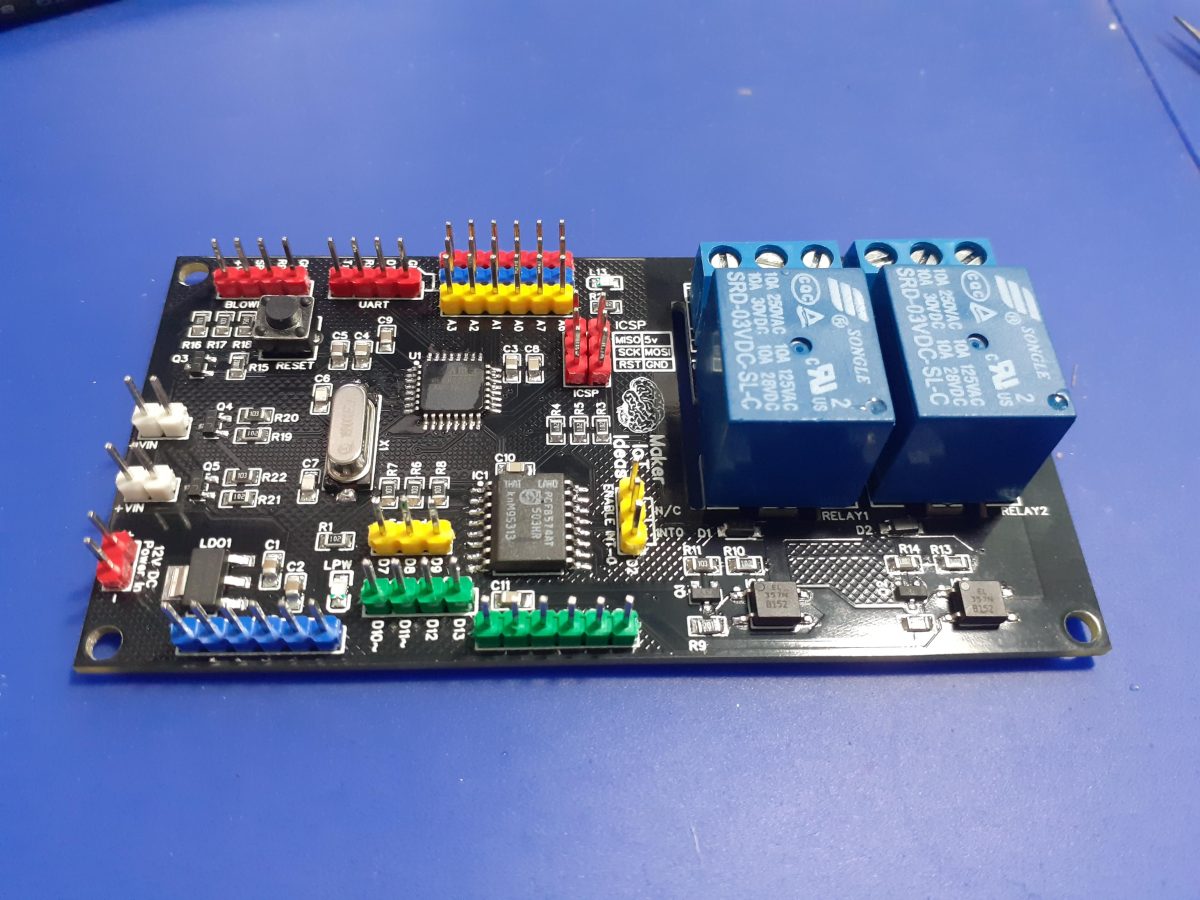
Let us take a quick look at the PCB.
Starting from the top left, we have the Blower/Fan Header.
This supplies 12v DC to the Blower/Fan motor, as well as the PWM signal to control the speed. ( Level converted up from 5v DC to 12V, and then reduced to 3.3v ) This may seem strange.
Let me explain for some more clarity…
The PWM input on the Blower/Fan is internally pulled HIGH to 12v ( by the motor driver circuitry – I can not change that, as it is a commercial unit.) The datasheet however calls for a 0v to 3.3v PWM signal to control the speed.
There is also a further input from the fan, which is a pulsed speed indicator (Fan RPM). This signal is 5v.
Next to that header, is a UART Header, with Rx, Tx and DTR signals, with a ground. I do no longer add USB-to-UART chips to my designs because they are not used a lot, take up unnecessary space, and I tend to program with ICSP anyway.
On the right of that, (Red/Blue/Yellow Header) are 5v, Gnd and 6 Analog inputs(A0-A3, A6,A7) [A4 and A5 being used for I2C]
The ICSP programming header is below that,
with a jumper to select PCF8574 interrupt on Pin D2 or not
This is followed by 6 GPIO (P2-P7) from the IO Expander, and
additional GPIO (D10, D11, D12, D13) , as well as (D7,D8,D9) [To be used with a Rotary Encoder]
Another 6way Ground header, as well as the 12v input (red), follows.
Finally, we have J1 and J2, which will switch 12v through BSS138 Mosfets to control static speed 12v cooling Fans (Only one of these is PWM capable)
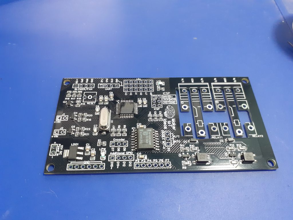
The 2 Relays are optically isolated from the controller and mains isolation cutouts are provided to further keep DC and AC voltages well away from each other. [ they really don’t play well together, don’t they ?]
This wraps up the quick PCB description.
Schematic
The Schematic is below, along with a download link ( zip format, with PNG image files)
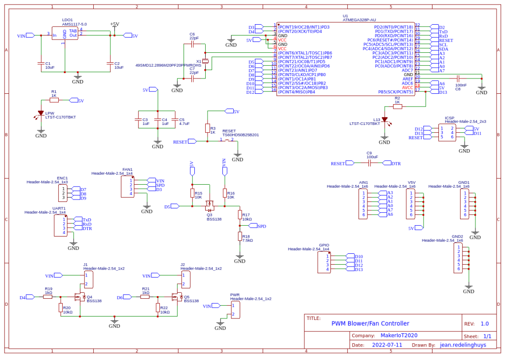
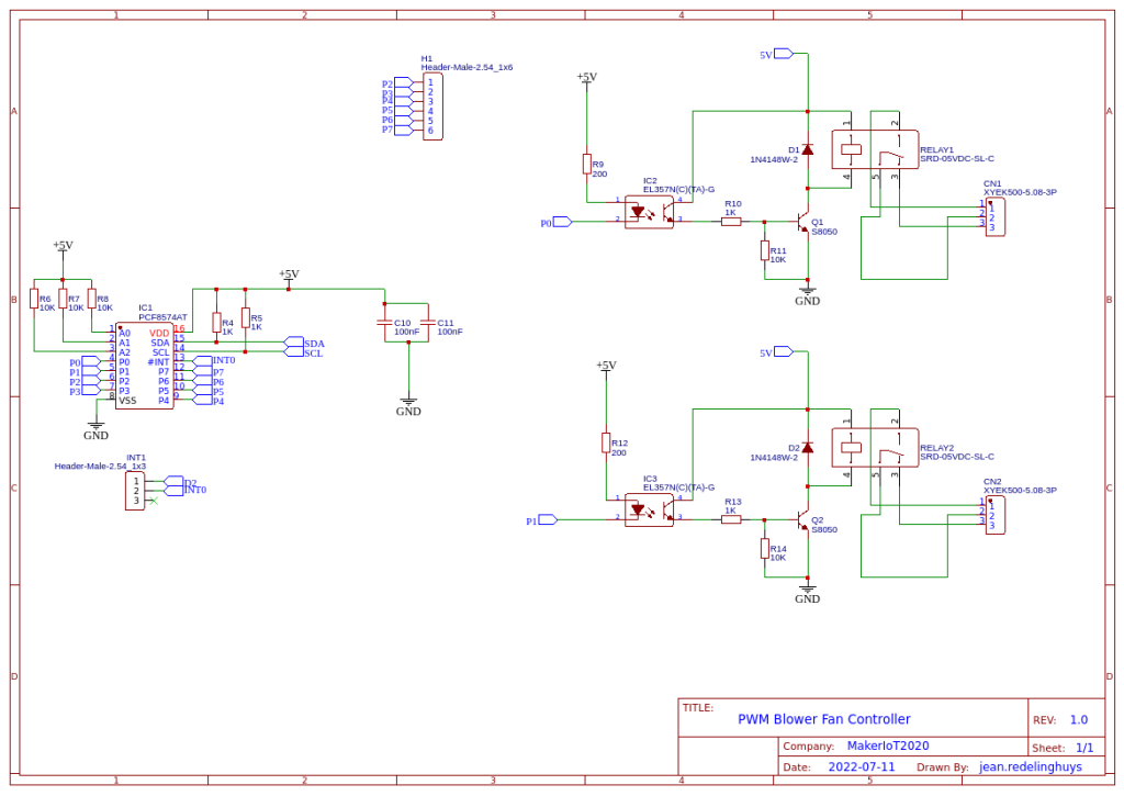
Schematic_PWM-Fan-Controller-with-RE_2022-08-19Download
Some more pictures
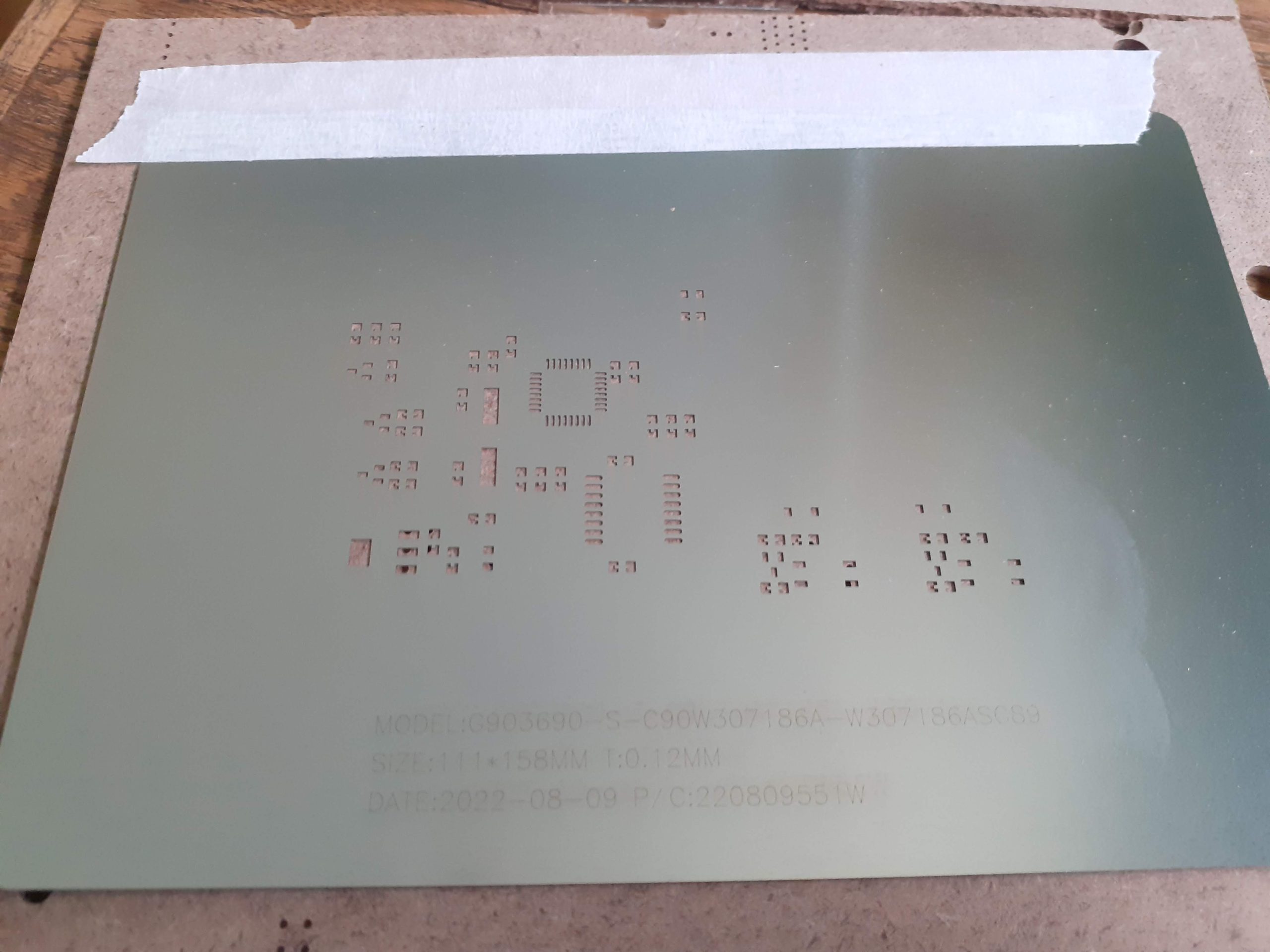
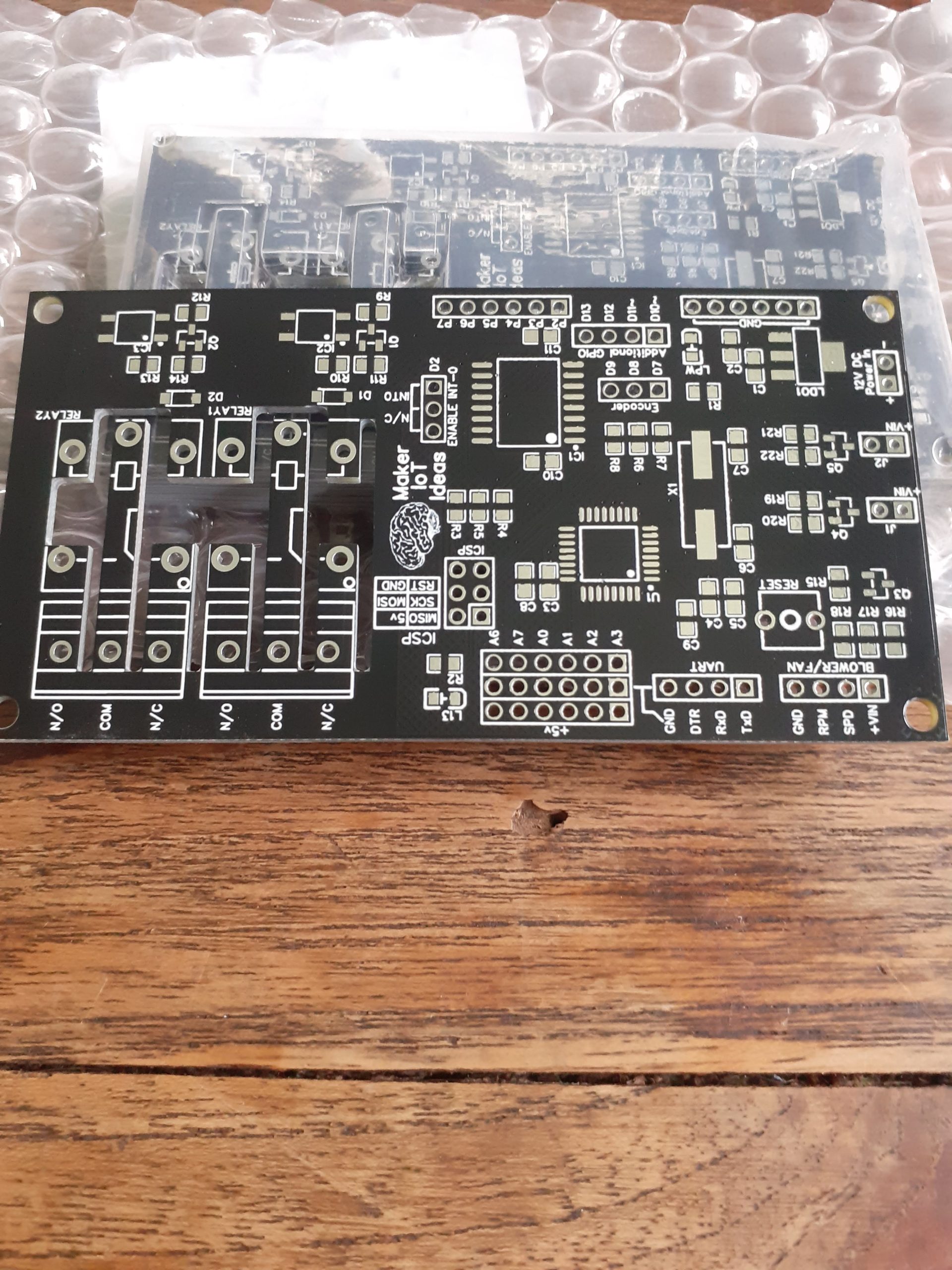
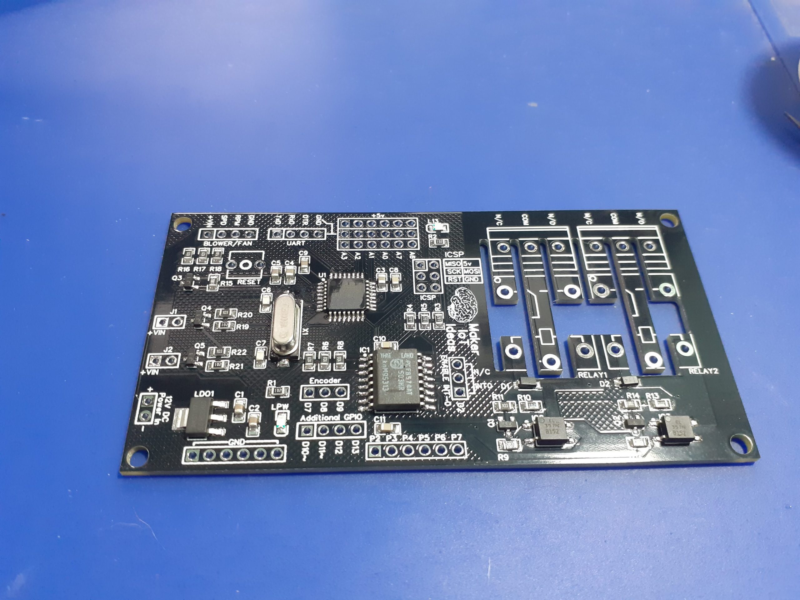
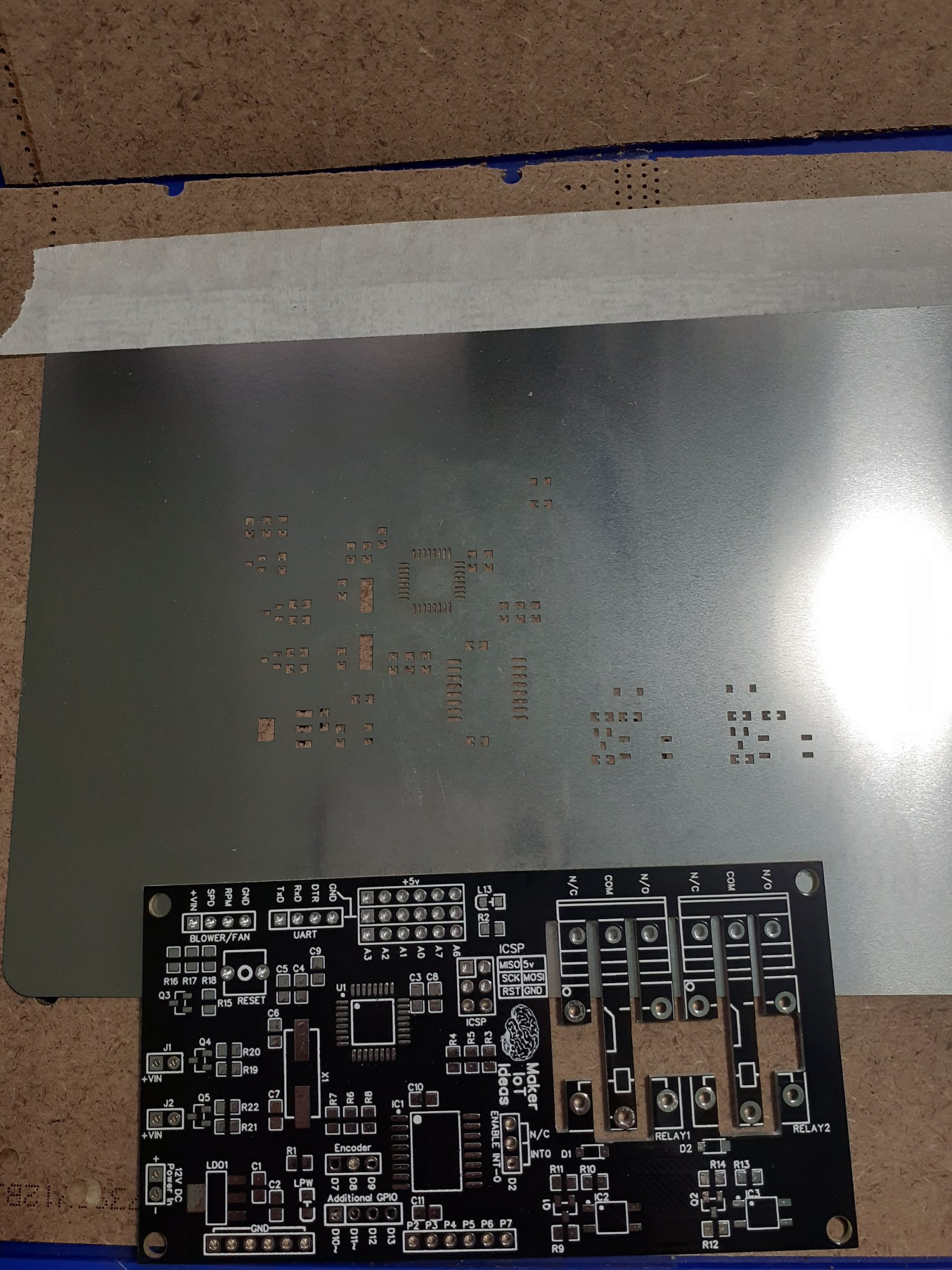
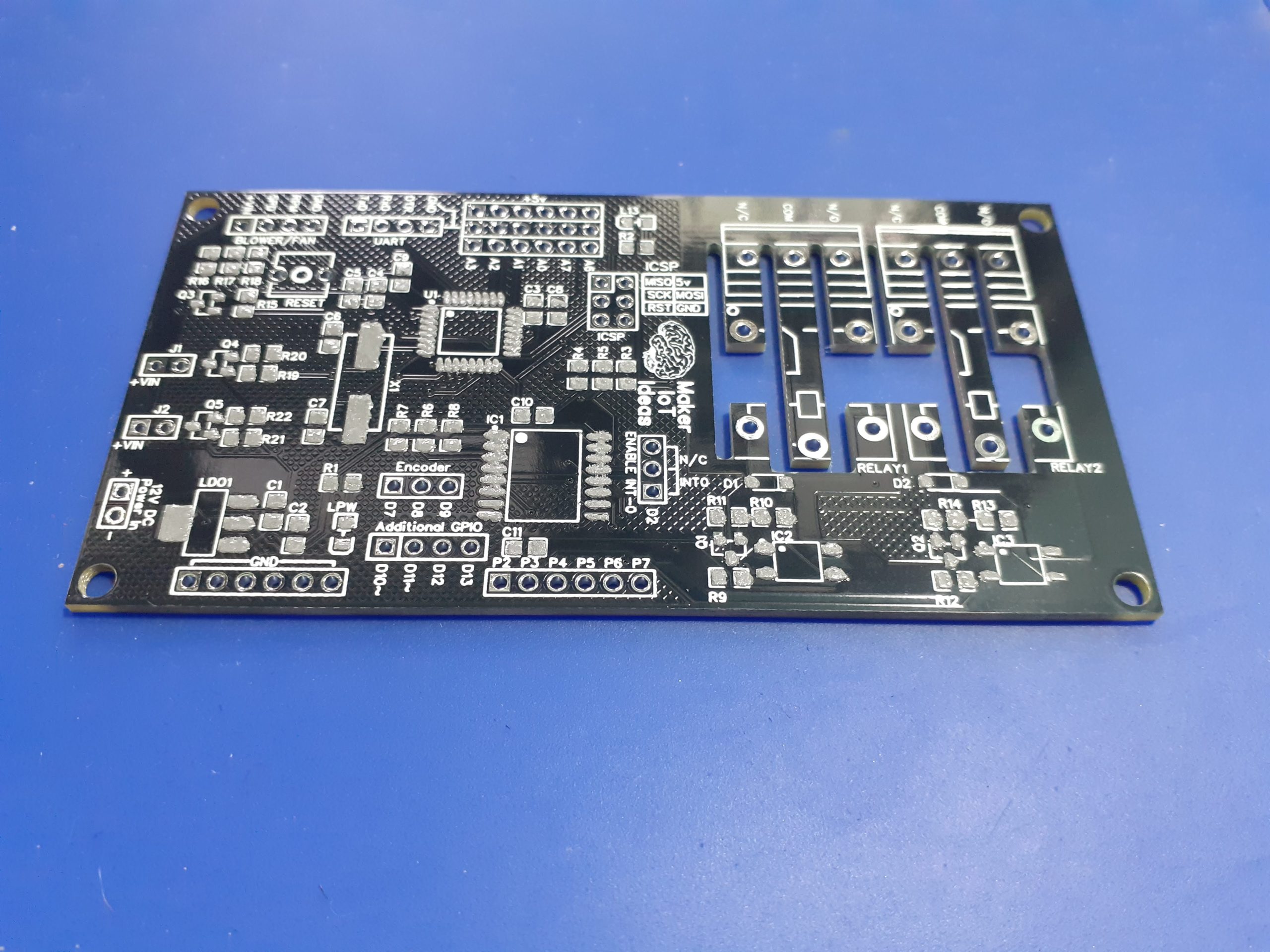
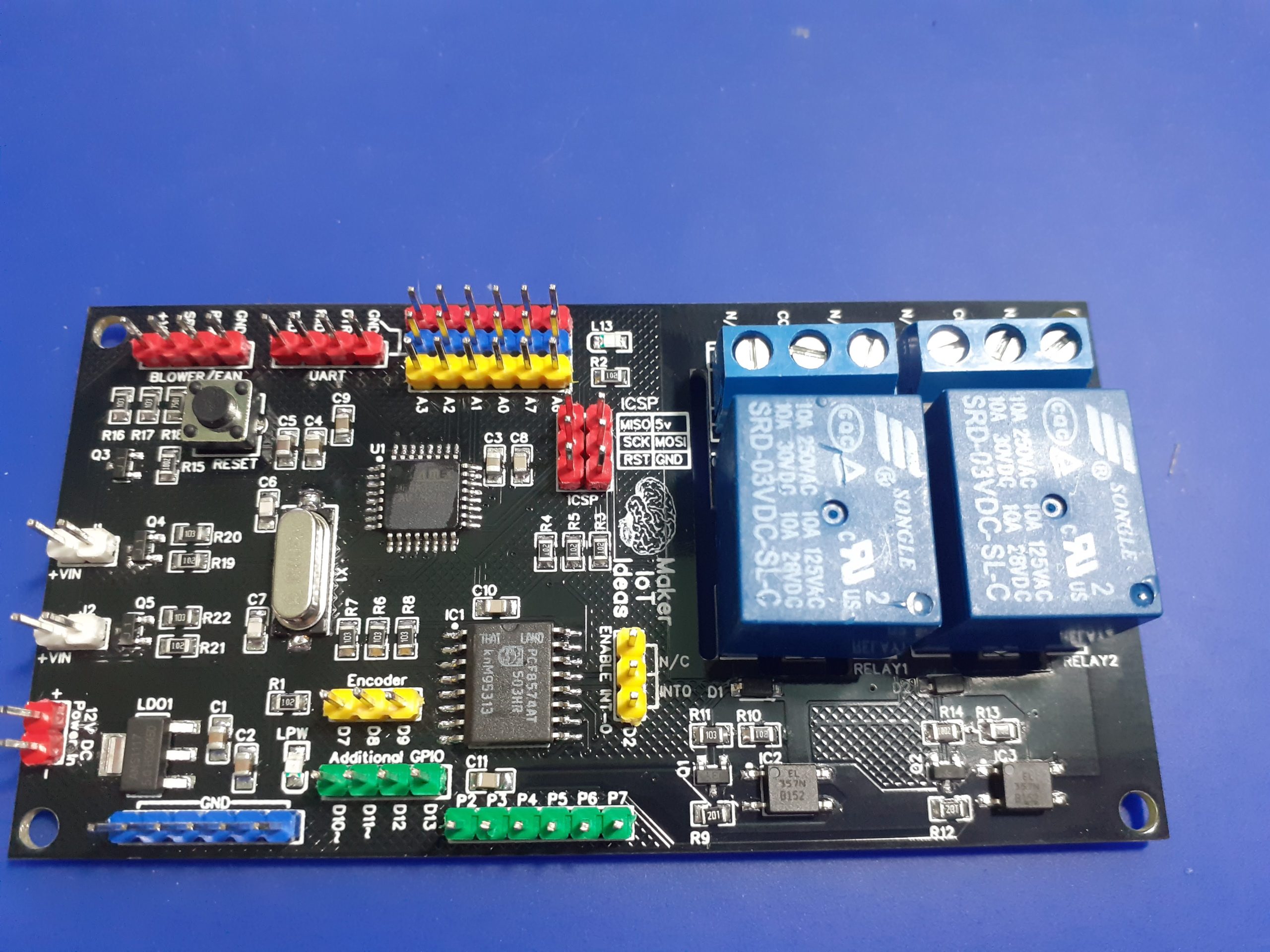
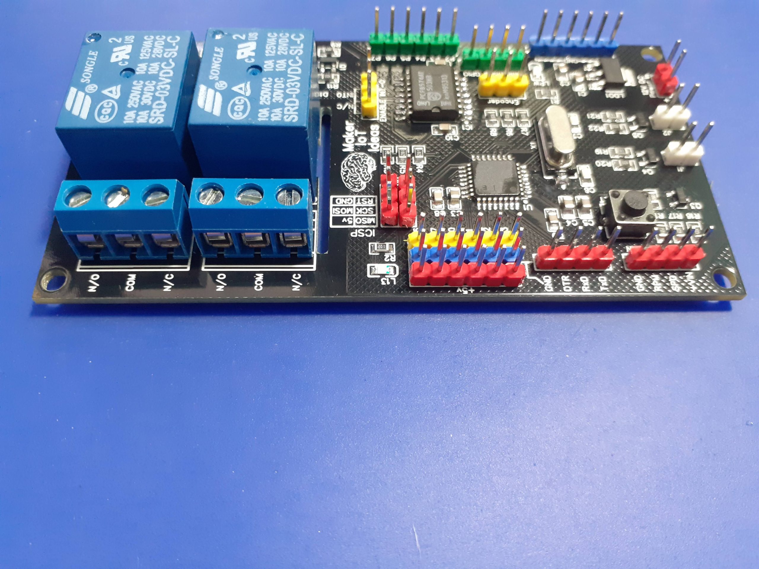
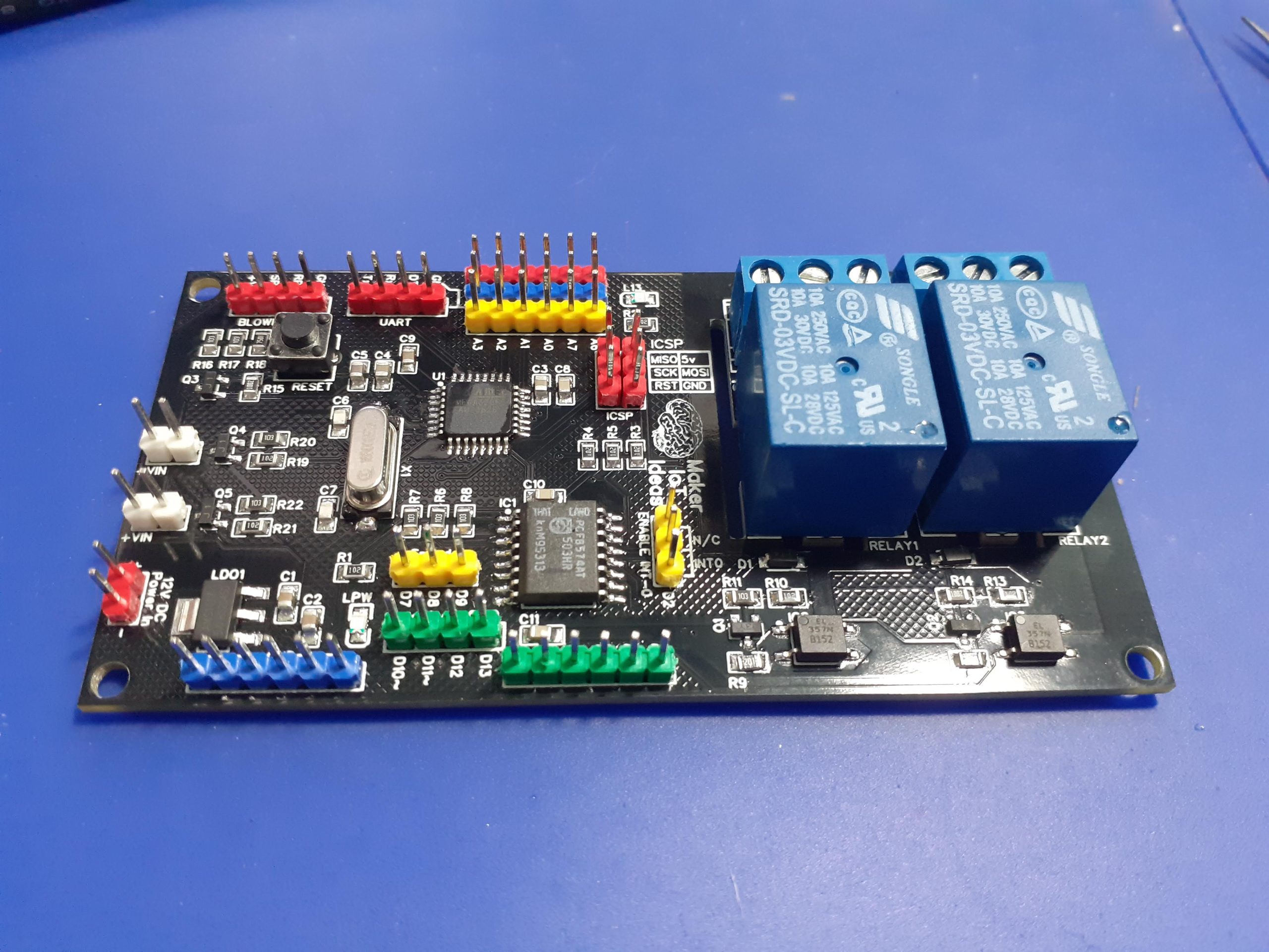
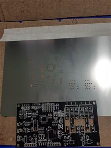
I use stencils with almost all of my SMD assembly. It saves a lot of time, makes for even solder paste application, and prevents the mess associated with applying solder paste with a syringe, or even worse a skewer-stick or something similar. They do cost extra though, but I find it well worthwhile in comparison to the mess and time that they save.
const int encFWD = 8;
const int encREV = 7;
int aState;
int aLastState;
int encDir;
int encTurned = LOW;
int encLastState;
int encValue = 0;
int lastEncValue;
const int encInc = 10;

unsigned long lastEncDebounce = 0;
unsigned encDebounceDelay = 50;
const int encBtn = 9;
int encButtonState;
int lastEncBtnState = LOW;
int EncBtnValue = LOW;
int encBtnState;

void setup() {
  //Rotary Encoder
  pinMode(encFWD,INPUT_PULLUP);
  pinMode(encREV,INPUT_PULLUP);
  pinMode(encBtn,INPUT_PULLUP);
  encTurned = LOW;
  encLastState = digitalRead(encFWD);
  //Serial
  Serial.begin(115200);
  //Status LED on D13
  pinMode(13,OUTPUT);
  digitalWrite(13,LOW);
}

void loop() {
  lastEncValue = encValue;
 //Handle the Encoder Push Button
 encBtnState = digitalRead(encBtn);
 if (encBtnState != lastEncBtnState) {
    lastEncDebounce = millis();
 }
 if ((millis() - lastEncDebounce) > encDebounceDelay) {
    if (encBtnState != encButtonState) {
        encButtonState = encBtnState;
        if (lastEncBtnState == LOW) {
          EncBtnValue = !EncBtnValue;
        }
    }
 }
 lastEncBtnState = encBtnState;
 // Handle the Rotary Encoder Dial
 aState = digitalRead(encFWD);
 if (aState != aLastState) {
    if (digitalRead(encREV) != aState) {
       if (encTurned == LOW) {
          encLastState = encTurned;
          encTurned = HIGH;
       } else {
          encTurned = LOW;
       }
       if ((encValue < 300) && (encDir == 0)){
          if ((encLastState == LOW) && (encTurned == HIGH)){
            encValue = encValue + encInc;
            encDir = 1;
          }
       }

    } else {
      if (encTurned == LOW) {
        encLastState = encTurned;
        encTurned = HIGH;
      } else {
        encTurned = LOW;
      }
      if ((encValue > 0) && (encDir == 0)){
          if ((encLastState == LOW) && (encTurned == HIGH)){
            encValue = encValue - encInc;
            encDir = 2;
          }
      }
    }
    encLastState = encTurned;
}
aLastState = aState;
encDir = 0;
// Print Some Status
if (encValue != lastEncValue) {
  Serial.print("Encoder Value Changed from ");
  Serial.print(lastEncValue);
  Serial.print(" to ");
  Serial.println(encValue);
}
digitalWrite(13,EncBtnValue);


}
PCB_PWM-Fan-Controller-with-RE
*PCBWay community is a sharing platform. We are not responsible for any design issues and parameter issues (board thickness, surface finish, etc.) you choose.
- Comments(0)
- Likes(0)
- 0 USER VOTES
- YOUR VOTE 0.00 0.00
- 1
- 2
- 3
- 4
- 5
- 6
- 7
- 8
- 9
- 10
- 1
- 2
- 3
- 4
- 5
- 6
- 7
- 8
- 9
- 10
- 1
- 2
- 3
- 4
- 5
- 6
- 7
- 8
- 9
- 10
- 1
- 2
- 3
- 4
- 5
- 6
- 7
- 8
- 9
- 10
 More by Jean Redelinghuys MakerIoT2020
-
 PCB_MCP23008_2023-10-08
MCP23008 BreakoutI designed this breakout to assist me during prototyping my next version of the “RP...
-
 PCB_XiaoRP2040-Mouse-REV2
Xiao RP2040 Joystick Mouse – revision 2.00Revision 1.0 of the ProjectOver the last few months, I hav...
-
 Multi Purpose IO Card
Multi-Purpose IO CardWhen we are working on a prototype, we always need access to pushbuttons, encod...
-
 Variable Voltage Power Module
Powering electronics projects are always challenging. This Variable vol...
Variable Voltage Power Module
Variable Voltage Power ModulePowering electronics projects are always challenging. This Variable vol...
-
 I2C Matrix Keypad
An I2C Matrix KeypadThe completed I2C Matrix KeypadIn a previous post this month I introduced my 4×4...
-
 ESP32-S Development Board, in "Arduino Uno" form factor
UPDATE 24/06/2023:This board now has a Hardware Revision 2.0 available. It is the same board but wit...
-
 W307186ASC94_Gerber_PCB_USB-Ports
USB Power Supply ModuleUSB Ports are quite handy to power all our day-to-day electronic devices, but...
-
 Atmega 328P based PWM controller Card
ATMega 328P Based PWM controller CardAs part of my recent ESP-12E I2C Base Board project, I designed...
-
 W307186ASC71_Gerber_PCB_ESP-Now Remote
Today we will look at the remote control unit for the Robotic Toy Car – Part 6.The project is close ...
-
 W307186ASV69_Gerber_PCB_Robot-Car-MCU-Board Prototype
In our last project, we started working on repurposing an old toy car. In this part, Robot Toy Car –...
-
 W307186ASV62_Gerber_PCB_DUAL-H-Bridge
by makeriot2020 on May 27, 2022Many of us have old toys laying around the house, they belong to ou...
-
 CAN-BUS Breakout
Breadboard Compatible CAN-BUS Breakout ModuleWhat is this:Some of us have already used the commonly ...
-
 RA-02 Breakout with Level converters
Breadboard and beginner-friendly RA-02 Breakout ModuleMost Makers and electronics enthusiasts may al...
-
 ATMEGA328P Module with integrated LoRa and CAN Bus
ATMEGA328P Module with integrated LoRa and CAN-BUSINTRODUCTIONIn my quest to perfect my LoRa telemet...
-
 Sx127x-Ra-02-Test-Module with ATMEGA328P-AU
SX127x LoRa/FSK/OOK Prototype Radio BoardI recently had a requirement to do some automation/telemetr...
-
 USB-ASP Programmer ATMEGA8
Build your own USB-ASP Programmer CloneBymakeriot2020 FEB 21, 2022 Arduino, ASP programmerUsing mor...
-
 ATTiny1616-LIGHT-Controller-with-CAN_B_PCB_ATTiny1616-LIGHT-Controller-with-C_2024-09-11
Assembly of the ATTiny1616 Can bus controller PCBThe Assembly of the ATTiny1616 Can Bus Controller P...
-
 ATTiny1616QFN-CAN-Remote-Neopixel-Ligh_PCB_ATTiny1616QFN-CAN-Remote-Neopixel-2024-09-11_2024-09-11
NeoPixel CAN-Bus Module with local controlAs part of my current project to add NeoPixels to the cabi...
-
-
AEL-2011 Power Supply Module
515 0 2 -
AEL-2011 50W Power Amplifier
475 0 2 -
-
-
Custom Mechanical Keyboard
691 0 0 -
Tester for Touch Screen Digitizer without using microcontroller
323 2 2 -
Audio reactive glow LED wristband/bracelet with NFC / RFID-Tags
306 0 1 -
-
-


