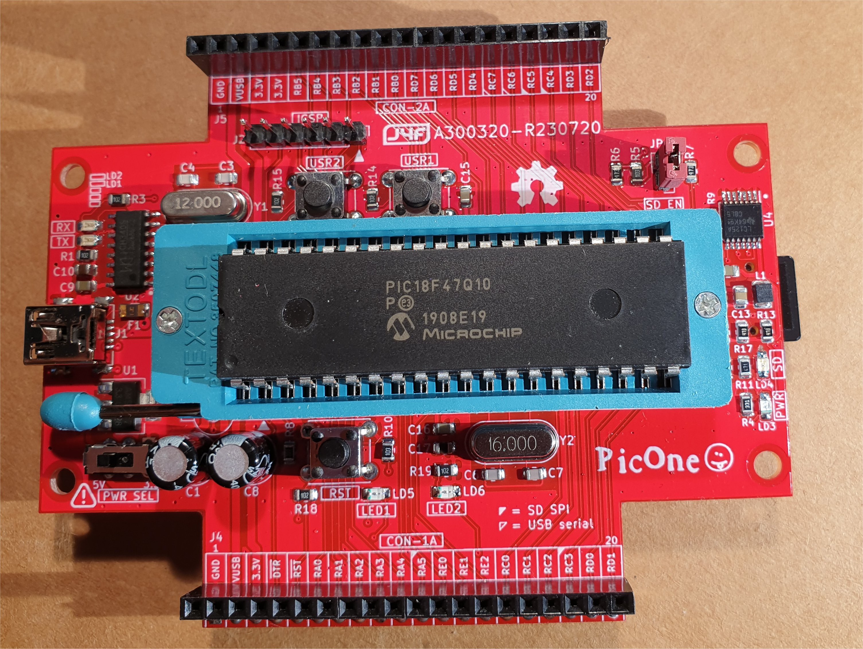
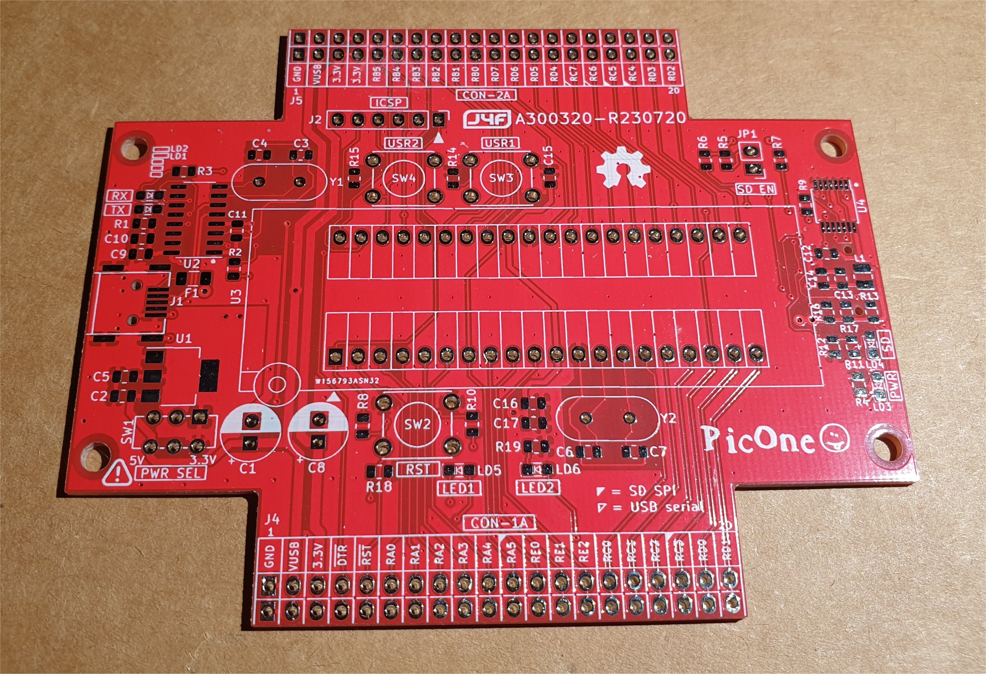
PicOne (PIC18F47Q10)
I was searching a DIL MCU for another "project" and found this one that seems interesting. It is cheap and with a lot of features, so i did a board to play with it.
PIC18F47Q10 main features:
- internal 64MHz oscillator
- 128 KB Flash Program Memory with self read/write capability
- 3728 Bytes Data SRAM Memory
- 1024 Bytes of EEPROM
- 10-bit ADC, 35 channels
- 8 x Configurable Logic Cell (CLC)
- 2 x I2C/SPI
- 2 x EUSART
PicOne main features:
- onboard USB-serial adapter
- onboard micro-SD with level translators
- power selector (5V or 3.3V)
- ICSP standard connector
- 2 user keys
- 2 user leds
- ZIF or standard MCU socket
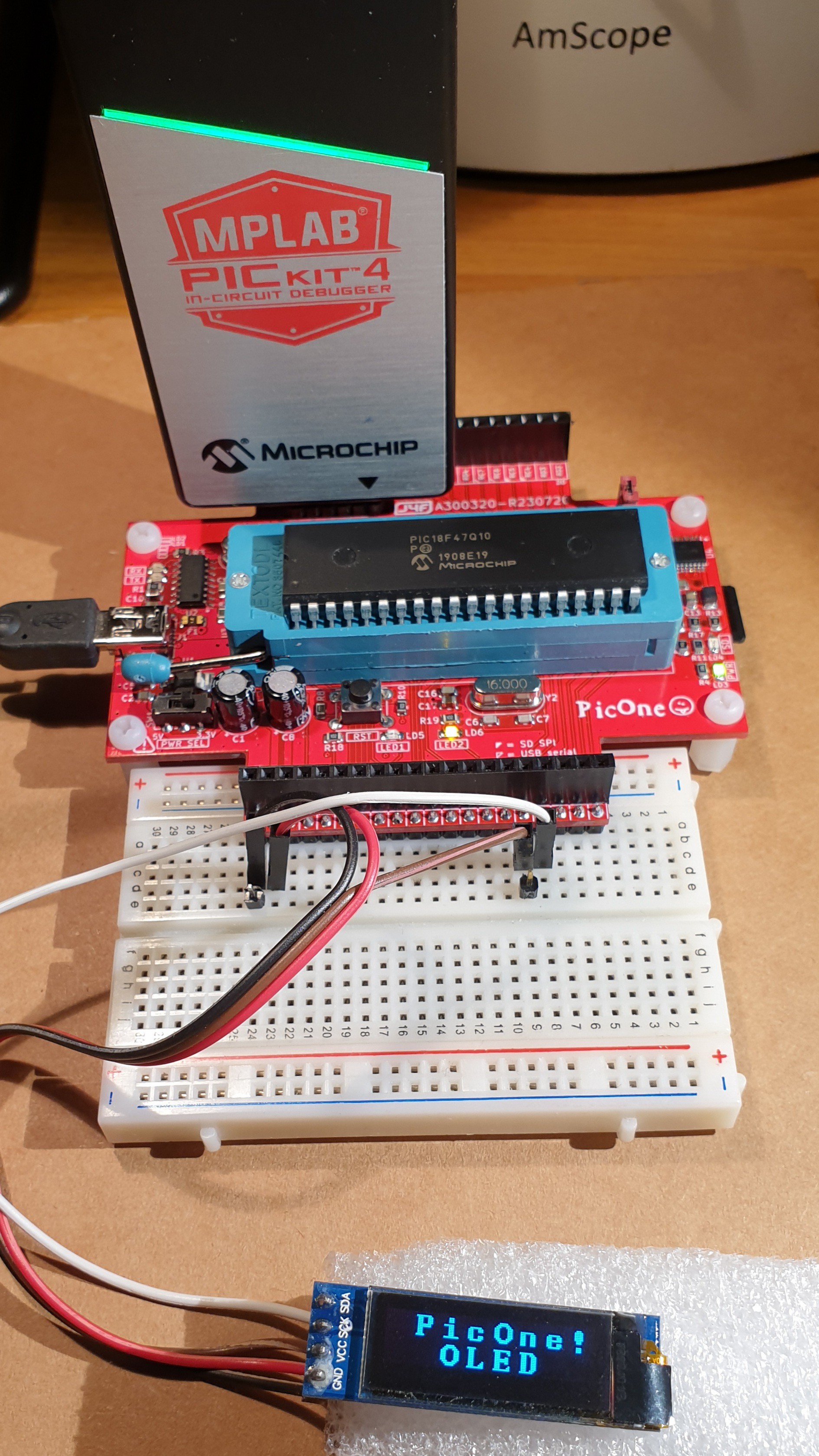
- plug-able into breadboards
SW1 (PWR-SEL)
The SW1 switch allows to select the working voltage for the PIC MCU (U3) and for the USB-serial adapter (U2). It is possible select 5V or 3.3V. This will change the corresponding logic levels of the I/O pins.
Please note that the level translator U4 takes care to allow the use of the micro-SD regardless the position of the power selector SW1.
WARNING: the SW1 switch position must be changed only when the board is not powered!
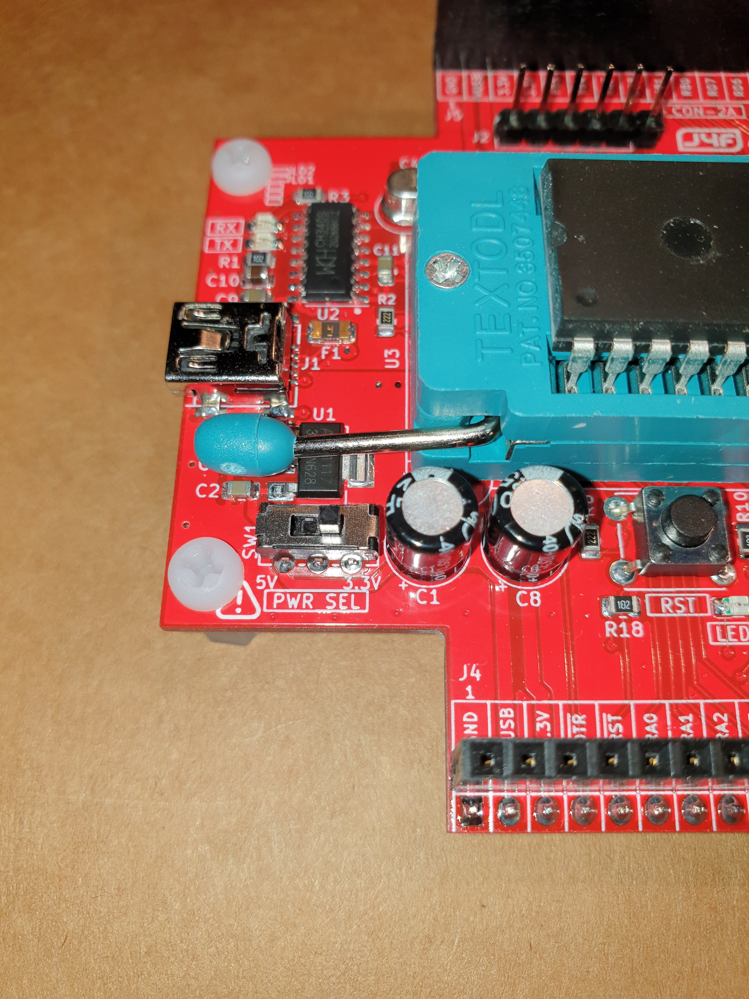
C6 AND C7 CAPACITORS
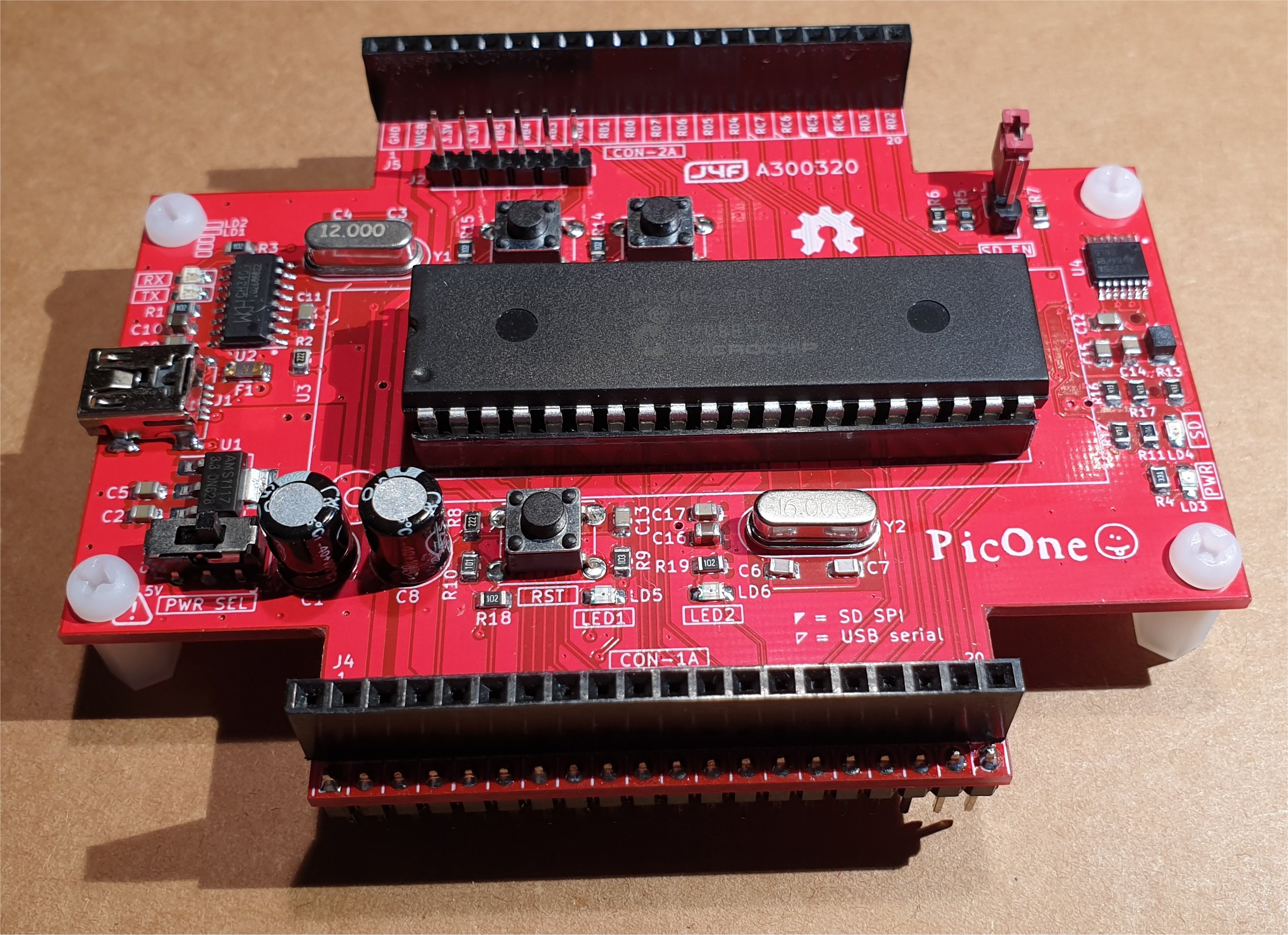
If you use a ZIF socket for the MCU, C6 and C7 (see the schematic) must be 22pF (NPO, 50V rated). If you use a normal socket C6 and C7 must be 27pF (NPO, 50V rated). This results from a higher pin to pin capacity of the ZIF socket than the normal one.
In the following image a board with a normal socket (previous PCB revision):
SJ1 AND SJ2 SOLDER BRIDGES
To allow the LED1 and LED2 led to turn on you have to bridge the two solder jumpers SJ1 and SJ2 on the bottom side of the PCB.
JP1 (SD-EN) JUMPER
To enable the onboard micro SD you have to jumper JP1 (SD-EN).
If you want use the RA4, RC5, RC3, RC4 MCU pins as general GPIO (they are used as CS, MOSI, SCK and MISO signals for the onboard micro-SD), leave JP1 open. This will disable the U4 level translator used for the micro-SD (see schematic).
If you are using the RC4 MCU pin as general GPIO (JP1 open), take into account that when the MCU is powered at 5V there might be a small current (about 3mA @ 5V) trough R9 if the RC4 pin is driven HIGH. So an external logic must be able to provide it eventually.
THE ICSP (J2) CONNECTOR
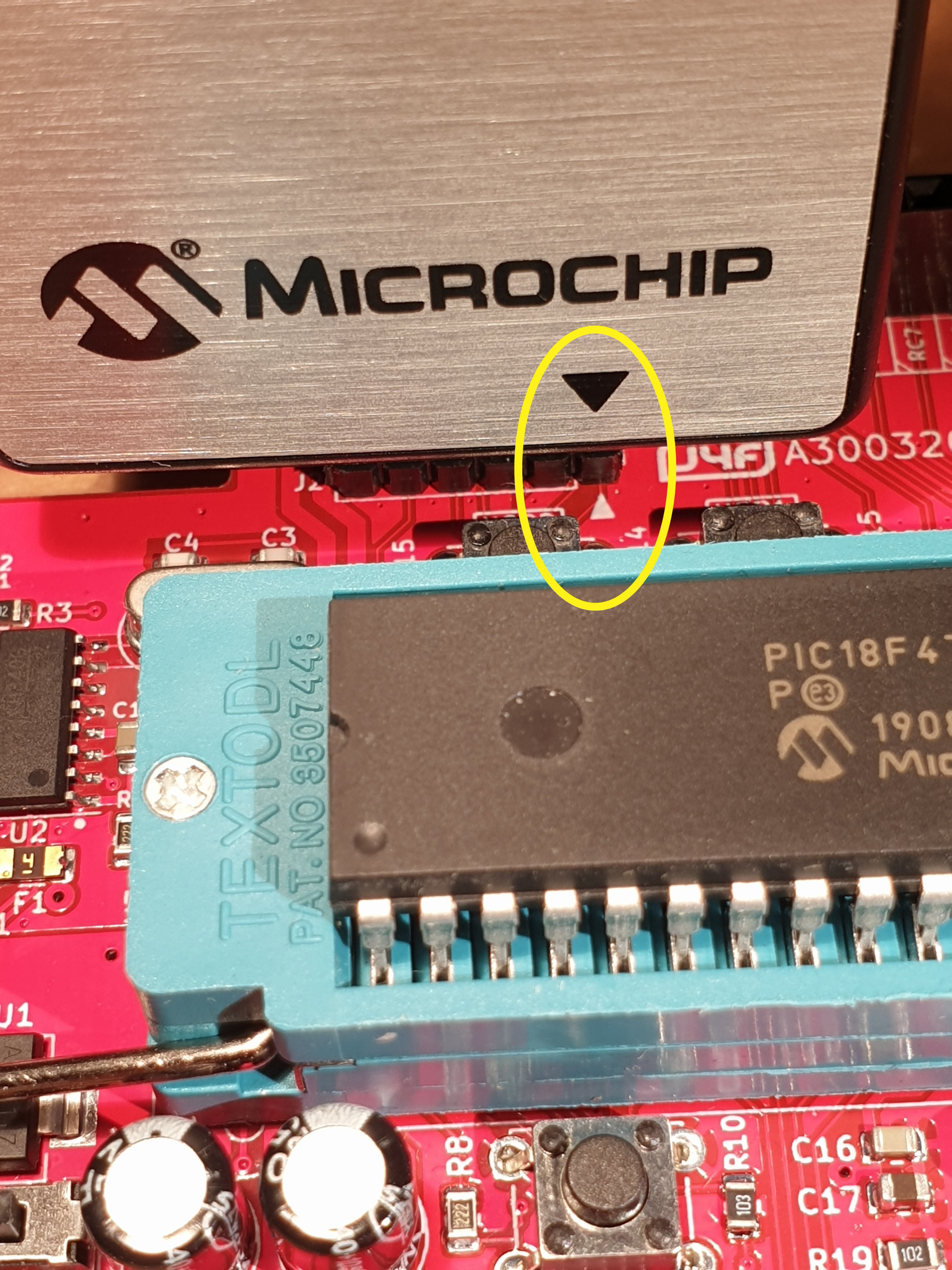
To program/debug the PIC MCU you need a PicKit or another suited programmer. The ICSP (J2) connector allows to connect the programmer to the board. On the PCB there is a mark for the pin 1 that must mach with the corresponding mark on the programmer. In the following image is shown the a PicKit4 directly attached on the ICSP connector:
WARNING: Remember to power off the board before to connect or remove the PicKit programmer! (see the PicKit Manual for further information).
WARNING: The programmer must be set to "power the target from the board".
INSERTING THE MCU (U3) INTO THE ZIF SOCKET
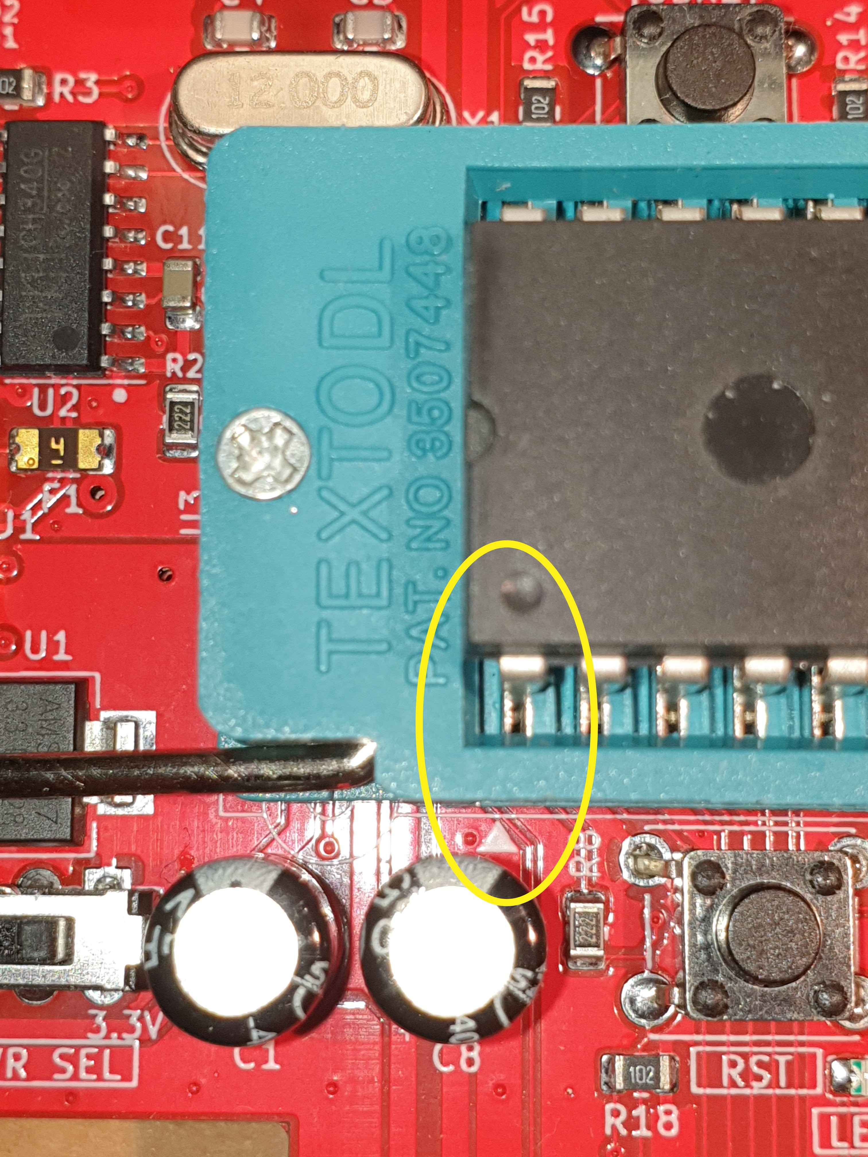
When inserting the PIC MCU (U3) into the ZIF socket pay attention to the pin 1 mark on the PCB:
* * PROTOTYPE EXAMPLE * *
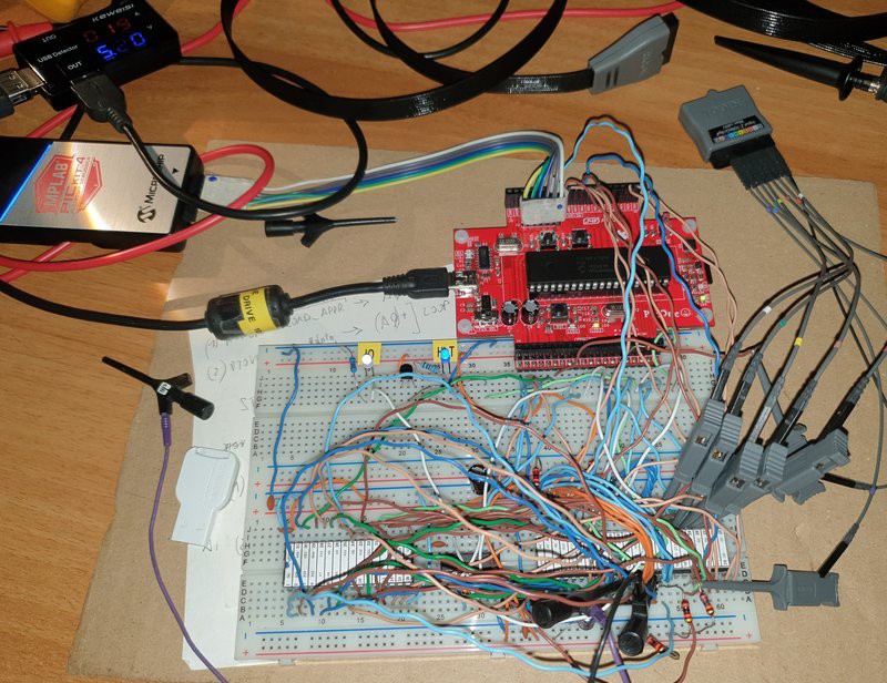
In the first phase of the design of the 68k-MBC (retro SBC with a 68008 CPU) I've used a prototype on a breadboard to check the basic "concepts":
To make the firmware for the PIC18F47Q10 I've used MPLAB X IDE with the MCC plugin.
Here a short video with an automated assembler toolchain using Easy68K as assembler and the sLoad boot mode, a custom SW utility to load from the serial port and execute a Motorola S-record formatted executable:
To allow a real automated toolchain an auto-reset circuit on the breadboard takes the DTR signal from the serial-USB adapter and uses it to reset the MCU (like in the Arduino Uno board), so it is possible reset the breadboard from a batch file running in the PC using a macro of Tera Term.
NOTE: All the details and updates to build the board including some MPLABX examples are in this main page:
https://hackaday.io/project/174282.
PicOne (PIC18F47Q10)
*PCBWay community is a sharing platform. We are not responsible for any design issues and parameter issues (board thickness, surface finish, etc.) you choose.

Raspberry Pi 5 7 Inch Touch Screen IPS 1024x600 HD LCD HDMI-compatible Display for RPI 4B 3B+ OPI 5 AIDA64 PC Secondary Screen(Without Speaker)
BUY NOW
ESP32-S3 4.3inch Capacitive Touch Display Development Board, 800×480, 5-point Touch, 32-bit LX7 Dual-core Processor
BUY NOW
Raspberry Pi 5 7 Inch Touch Screen IPS 1024x600 HD LCD HDMI-compatible Display for RPI 4B 3B+ OPI 5 AIDA64 PC Secondary Screen(Without Speaker)
BUY NOW- Comments(0)
- Likes(3)
 Log in to post comments.
-
 Engineer
Oct 23,2024
-
 Engineer
Apr 24,2021
-
 Scott Beasley
Aug 14,2020
- 0 USER VOTES
- YOUR VOTE 0.00 0.00
- 1
- 2
- 3
- 4
- 5
- 6
- 7
- 8
- 9
- 10
- 1
- 2
- 3
- 4
- 5
- 6
- 7
- 8
- 9
- 10
- 1
- 2
- 3
- 4
- 5
- 6
- 7
- 8
- 9
- 10
- 1
- 2
- 3
- 4
- 5
- 6
- 7
- 8
- 9
- 10
 More by Just4Fun
-
 Dual channel RS232 adapter
This is a simple board I made to play with my FPGA board "The Thing". This board has two RS-232 chan...
-
 uCom (a RS232 adapter for the Z80-MBC2)
uCom (micro-Com) is a RS232 adapter for the Z80-MBC2 (https://hackaday.io/project/159973). It has a ...
-
 uTerm (a VT100-like terminal for the Z80-MBC2)
uTerm (micro-Term) is a VT100-like terminal for the Z80-MBC2 (https://hackaday.io/project/159973). I...
-
 "The Thing": FPGA + STM32, Multicomp compatible
### DESCRIPTIONTwo dev boards into one: a STM32 based Arduino ("Maple Mini" compatible) and a Cyclon...
-
 ESP-01 NanoBoard (ESP8266)
### DESCRIPTIONThe ESP-01 NanoBoard is a little "motherboard" for the well known ESP-01 ...
-
 Z80-MBC2: 4ICs homemade Z80 computer
### DESCRIPTIONThe Z80-MBC2 is an easy to build Z80 SBC (Single Board Computer with 8MHz Z80, 128kB ...
-
 SPP (Standard Parallel Port) Adapter for the 68k-MBC
The Standard Parallel Port (SPP) Adapter board allows to use the GPIO port of the "retro-board" 68k-...
-
 uTerm2-S: a multi-emulation color RS232 terminal
* * HARDWARE OVERVIEW * *The uTerm2-S (micro Term2 stand-alone) is an easy to build multi-emulation ...
-
 68k-MBC: a 3 ICs 68008 homebrew computer
* * DESCRIPTION * *The 68k-MBC is an easy to build 68008 CPU SBC (Single Board Computer), using only...
-
 Parallel Printer (SPP) Emulator Shield
* * HARDWARE OVERVIEW * *Playing with retro-computers or messing with dated instruments a simple SPP...
-
 Azz!Duino: A W806 (Winner Micro) MCU on a Arduino Mega shaped board
* * OVERVIEW * *The W806 is an interesting low cost MCU made by Winner Micro. There is a page about ...
-
 uHat add-on board for uTerm2-S
It is a little add-on board with a PSRAM (specific for the ESP32) and a microSD socket. I've called ...
-
 PicOne (PIC18F47Q10)
I was searching a DIL MCU for another "project" and found this one that seems interesting. It is che...
-
 V20-MBC: an easy to build 8088 + 8080 computer
DescriptionThe V20-MBC2 is an easy to build V20HL CPU SBC (Single Board Computer). It follows the sa...
-
 CH552 Dragon
* * HARDWARE OVERVIEW * *The CH552 is a little MCU with a 8051 core and a USB interface, and is damn...
-
 ARMando (STM32F030R8 board)
I wanted a board with a "standard" form factor as the common dev boards, but that could be easily in...
-
 RC-Z8BASIC
Never used a Z8 MCU before, but when I found that chip "forgotten" for decades and started to read t...
-
 uTerm-S: stand-alone RS232 VT100 terminal with VGA/PS2
* * HARDWARE OVERVIEW * *uTerm-S (micro-Term Stand-alone) is a legacy RS232 VT100-like terminal. It ...
-
 Dual channel RS232 adapter
This is a simple board I made to play with my FPGA board "The Thing". This board has two RS-232 chan...
-
 uCom (a RS232 adapter for the Z80-MBC2)
uCom (micro-Com) is a RS232 adapter for the Z80-MBC2 (https://hackaday.io/project/159973). It has a ...
-
 uTerm (a VT100-like terminal for the Z80-MBC2)
uTerm (micro-Term) is a VT100-like terminal for the Z80-MBC2 (https://hackaday.io/project/159973). I...
-
 "The Thing": FPGA + STM32, Multicomp compatible
### DESCRIPTIONTwo dev boards into one: a STM32 based Arduino ("Maple Mini" compatible) and a Cyclon...
-
 ESP-01 NanoBoard (ESP8266)
### DESCRIPTIONThe ESP-01 NanoBoard is a little "motherboard" for the well known ESP-01 ...
-
 Z80-MBC2: 4ICs homemade Z80 computer
### DESCRIPTIONThe Z80-MBC2 is an easy to build Z80 SBC (Single Board Computer with 8MHz Z80, 128kB ...
-
 SPP (Standard Parallel Port) Adapter for the 68k-MBC
The Standard Parallel Port (SPP) Adapter board allows to use the GPIO port of the "retro-board" 68k-...
-
 uTerm2-S: a multi-emulation color RS232 terminal
* * HARDWARE OVERVIEW * *The uTerm2-S (micro Term2 stand-alone) is an easy to build multi-emulation ...
-
 68k-MBC: a 3 ICs 68008 homebrew computer
* * DESCRIPTION * *The 68k-MBC is an easy to build 68008 CPU SBC (Single Board Computer), using only...
-
 Parallel Printer (SPP) Emulator Shield
* * HARDWARE OVERVIEW * *Playing with retro-computers or messing with dated instruments a simple SPP...
-
 Azz!Duino: A W806 (Winner Micro) MCU on a Arduino Mega shaped board
* * OVERVIEW * *The W806 is an interesting low cost MCU made by Winner Micro. There is a page about ...
-
 uHat add-on board for uTerm2-S
It is a little add-on board with a PSRAM (specific for the ESP32) and a microSD socket. I've called ...
-
-
-
Commodore 64 1541-II 1581 Floppy Disk Drive C64 Power Supply Unit USB-C 5V 12V DIN connector 5.25
443 1 4 -
-
-
-
-
-
-
-
Modifying a Hotplate to a Reflow Solder Station
1295 1 6 -
MPL3115A2 Barometric Pressure, Altitude, and Temperature Sensor
726 0 1


