Pico Clock
Story
Raspberry Pi foundation recently launched their first microcontroller based development board Raspberry Pi Pico. It is far advanced than arduino uno but not as much as ESP32. Anyways when I wanted to make something with it I was pretty limited because it has no wifi or bluetooth built into it so I can't make any IOT project with it. So I decided to make a clock instead.I designed a shield for Pico which contains an 128x32 OLED display, an RTC module, buzzer and a battery charging circuit. It has 5 different clock interfaces, that you can choose according to your choice. Along with that we also have a stopwatch and a timer alarm built into it.
DETAILS
This is PicoClock, a tiny digital clock shield for RPI Pico. Apart from the shield all you need a suitable size battery and that’s all about the hardware you need to make this project.
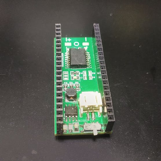
On one side of this shield we have DS3231 Real time clock IC then we have a Li-ion battery charging circuit based around HT4928s battery management IC. along with a JST connector to connect the battery and a buzzer.
Pin Connections :
SDA - GP6
SCL - GP7
BUTTON1 - GP1
BUTTON2 - GP14
BUZZER - GP16
BATTERY VOLTAGE - GP27
On the other side of the PCB we have a 0.91 inch oled display and two push buttons.
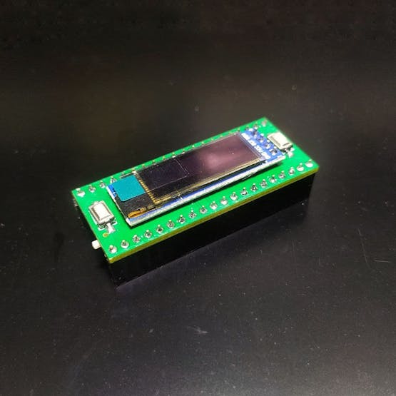
Pico supports both micropython and C. I use the basic example code for the DS3231 RTC and SSD1306 oled to make a simple clock in micropython. But the library functionalities was pretty limited and so my knowledge on microphthon. So I couldn't make much modifications to it
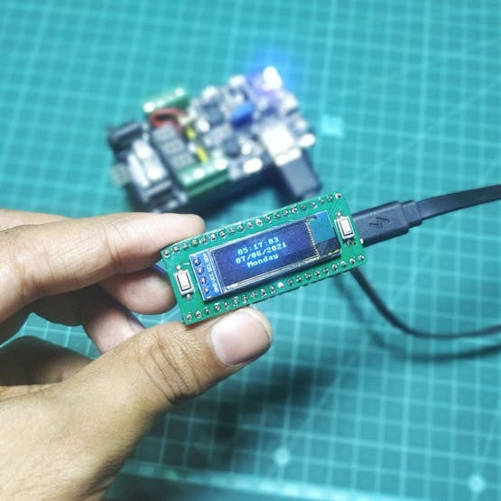
And since now that we also have official arduino support for it too so I switched to arduino IDE for programming. For that first you need to install the Raspberry pi pico board package on your IDE. The code is fairly large so I’d try to explain how it works.
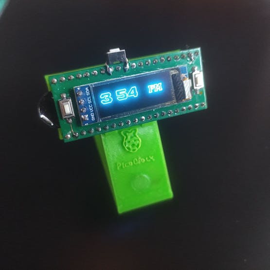
So when the display turns on we see this 12 hour format clock. There are 5 other clock interfaces and you can choose any of them as default. Press the right button to change a different mode.
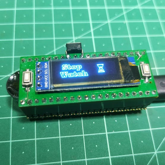
If you press the button on the left, it will go to other features on this module. Such as stopwatch. Now by clicking on the right button it will start counting. If you press the right button again it will show the laps time. Press the left button to reset the watch.
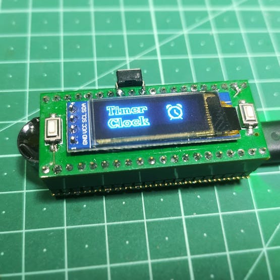
The next feature is the timer clock. Press the right button to set the timer. Press the left button to change the cursor, the right button for changing the parameters. the first position is for return, the next one is to set the seconds, then minute, then hour. And finally when you see the box that is to set the timer. And it will start counting down. When the timer is over you will see a termination message on the screen and a alarm tone started to buzz.
The last mode is settings where you can turn on or off the sound and it will mute the buzzer. Also you can see the battery voltage level. And if you want to turn off the display you can do that by pressing both buttons simultaneously. Press the reset button to turn it back on. And that’s pretty much it about the project.
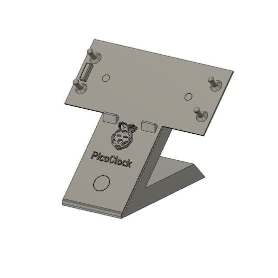
Finally I designed and 3d printed a desk stand for this module on fusion 360.
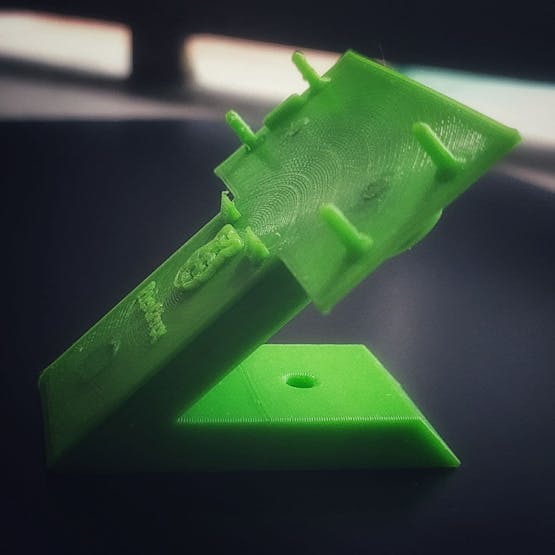
It’s a two part model that snap fits together. And that’s how I made my own portable digital clock. You can find all the details about this project on the github repo. Please watch the youtube video to learn more.
Tutorial Video:
Pico Clock
*PCBWay community is a sharing platform. We are not responsible for any design issues and parameter issues (board thickness, surface finish, etc.) you choose.

Raspberry Pi 5 7 Inch Touch Screen IPS 1024x600 HD LCD HDMI-compatible Display for RPI 4B 3B+ OPI 5 AIDA64 PC Secondary Screen(Without Speaker)
BUY NOW
ESP32-S3 4.3inch Capacitive Touch Display Development Board, 800×480, 5-point Touch, 32-bit LX7 Dual-core Processor
BUY NOW
Raspberry Pi 5 7 Inch Touch Screen IPS 1024x600 HD LCD HDMI-compatible Display for RPI 4B 3B+ OPI 5 AIDA64 PC Secondary Screen(Without Speaker)
BUY NOW- Comments(0)
- Likes(4)
 Log in to post comments.
-
 ugur tezer
Jun 20,2021
-
 SAYANTAN ElectroPoint4u
May 17,2021
-
 (DIY) C64iSTANBUL
Apr 23,2021
-
 MXKA03
Apr 23,2021
- 1 USER VOTES
- YOUR VOTE 0.00 0.00
- 1
- 2
- 3
- 4
- 5
- 6
- 7
- 8
- 9
- 10
- 1
- 2
- 3
- 4
- 5
- 6
- 7
- 8
- 9
- 10
- 1
- 2
- 3
- 4
- 5
- 6
- 7
- 8
- 9
- 10
- 1
- 2
- 3
- 4
- 5
- 6
- 7
- 8
- 9
- 10
-
10design
-
10usability
-
10creativity
-
10content
 More by SAYANTAN ElectroPoint4u
-
 How to make RGBW lights using Aluminium PCB
When it comes to making electronics projects, a custom PCB board is always one of the top priorities...
-
 ESP32 BLE GamePad
This is a DIY handheld gamepad, made using ESP32 microcontroller. You might have seen such game cont...
-
 12 Channel Ultimate Home Automation
ESP32 based 12 Channel IOT Home Automation using Blynk Application. Can be controlled using Physical...
-
 World's Slimmest NeoPixel LED Matrix
I always have this idea of what would have happened if we can put the components inside the pcb? Let...
-
 ESP-12E/F Breakout Board
Size:25.4mm x 30mmSignal Layers:2None Signal Layers:10Components:12Pads:57 Surface Pads:35 Plated Th...
-
 PCB Pyramid
In this project I built a rather interesting project which I thought a long time ago. Its basically ...
-
 3D printed Stepper Bot
This is a E.S.P32 based robot that I made which can not only be controlled over the internet but als...
-
 ESP32-C3 NodeMCU
This is a DropIn replacement for NodeMCU ESP8266 AMICA CP2102 WiFi Development Board. The pinout are...
-
 NeoPixel XL
What is it?If you ever been used or seen neopixel LED, then you will be familiar to this concept. It...
-
 ESP32 BLE Macro Keyboard
This is a wireless macro keyboard consist of 10 cherry MX key swathes with individual backlight. It ...
-
 DIY Novatrope
A DIY replica of the popular Novatrope project, an elegant kinetic kinetic sculpture using Attiny85,...
-
 Fanmade 7th Anniversary badge
This is a simple PCB badge that I designed for celebrate 7th anniversary of PCBway. It has 6 RGB bli...
-
 Reflow Hotplate Controller
Story :Last time I made a reflow soldering hotplate from a regular clothing iron. And it works prett...
-
 ESP Programmer
ESP8266 and ESP32 required some special arrangement to pull the chip into boot mode. Typically this ...
-
 Portable Power Supply for microcontroller projects
If you are working on a portable electronics project, or in a remote place where you can’t bring you...
-
 Pico Clock
StoryRaspberry Pi foundation recently launched their first microcontroller based development board R...
-
 Addressable Output using WS2811
So I was needed to control almost 200+ relays using one microcontroller and during research I found ...
-
 Portable wireless touch Remote
An ESP32 module comes with a lot of different features. One of such features is it’s touch capabilit...
-
 How to make RGBW lights using Aluminium PCB
When it comes to making electronics projects, a custom PCB board is always one of the top priorities...
-
 ESP32 BLE GamePad
This is a DIY handheld gamepad, made using ESP32 microcontroller. You might have seen such game cont...
-
 12 Channel Ultimate Home Automation
ESP32 based 12 Channel IOT Home Automation using Blynk Application. Can be controlled using Physical...
-
 World's Slimmest NeoPixel LED Matrix
I always have this idea of what would have happened if we can put the components inside the pcb? Let...
-
 ESP-12E/F Breakout Board
Size:25.4mm x 30mmSignal Layers:2None Signal Layers:10Components:12Pads:57 Surface Pads:35 Plated Th...
-
 PCB Pyramid
In this project I built a rather interesting project which I thought a long time ago. Its basically ...
-
 3D printed Stepper Bot
This is a E.S.P32 based robot that I made which can not only be controlled over the internet but als...
-
 ESP32-C3 NodeMCU
This is a DropIn replacement for NodeMCU ESP8266 AMICA CP2102 WiFi Development Board. The pinout are...
-
 NeoPixel XL
What is it?If you ever been used or seen neopixel LED, then you will be familiar to this concept. It...
-
 ESP32 BLE Macro Keyboard
This is a wireless macro keyboard consist of 10 cherry MX key swathes with individual backlight. It ...
-
 DIY Novatrope
A DIY replica of the popular Novatrope project, an elegant kinetic kinetic sculpture using Attiny85,...
-
 Fanmade 7th Anniversary badge
This is a simple PCB badge that I designed for celebrate 7th anniversary of PCBway. It has 6 RGB bli...
-
-
-
Modifying a Hotplate to a Reflow Solder Station
844 1 5 -
MPL3115A2 Barometric Pressure, Altitude, and Temperature Sensor
442 0 1 -
-
Nintendo 64DD Replacement Shell
374 0 2 -
V2 Commodore AMIGA USB-C Power Sink Delivery High Efficiency Supply Triple Output 5V ±12V OLED display ATARI compatible shark 100W
1084 4 2 -
How to measure weight with Load Cell and HX711
688 0 3


