
|
arduino IDEArduino
|
|

|
3D Printer (generic) |
Reflow Hotplate Controller
Story :
Last time I made a reflow soldering hotplate from a regular clothing iron. And it works pretty great. The only issue is it uses mains AC voltage which I don't feel super comfortable to work with so I tried low voltage DC approach.
The Idea :
The idea is simple, when you apply power to both ends of a conductor, it generates heat. So if we make a PCB that has a very lengthy trace and apply voltage to it’s end terminals it should generate enough heat to reflow a PCB. Key things to note here is that different solder paste has different melting point. and since my last experiment 200 to 220 degree celsius should be sufficient for the solder paste that I use.
Choosing PCB type :
So regular FR4 PCB is not a suitable option, But aluminium PCBs are made to withstand high temperatures and they spread the heat evenly throughout the entire surface. Although aluminium PCBs are bit more expensive, they are well suited for this job. So I started with designing the circuit.
PCB design :
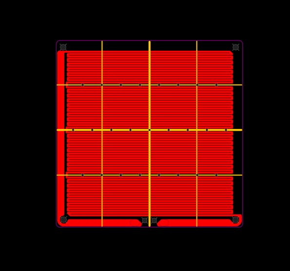
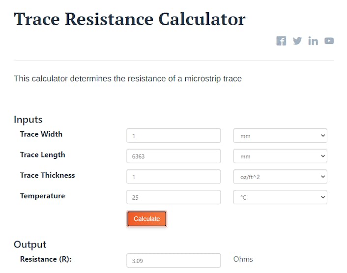
This will be the heated bed. An online calculator shows that the trace resistance will be 3 ohms.
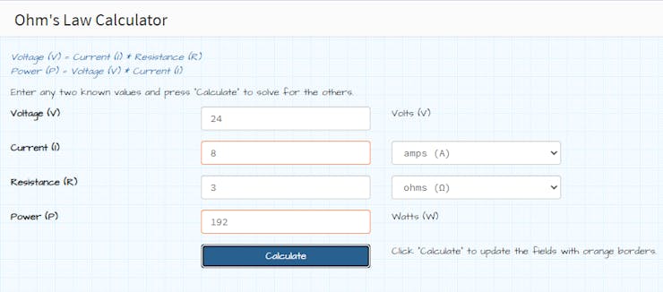
and at 24v it will draw about 200w of power.
Then I designed the controller circuit. I will use this TTGO T-Display module since it has a builtin TFT display. Along with MAX6675 ic with k type thermocouple. There are two mosfets to control the heatbed and a small cooling fan. After designing the PCB I head over to PCBway for manufacturing the PCB.
Initial Testing:
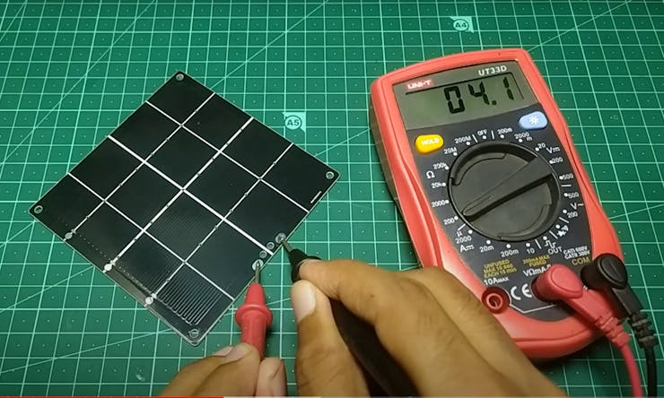
After getting the PCB I first measured the trace resistance and it’s 4 ohms which is slightly bigger than the previously calculated value. Then test the maximum temperature. So at 24 volts it draws about 7 amps of current and the temperature rises to 178 degree Celsius.
At that time the connection was interrupted because one of the wires got disconnected from the PCB. Because the entire PCB was heating up so the solder joint melted. Later I fixed it by using alligator clips instead of soldering the wire directly. But Still I couldn’t reach the desired temperature. So I reduced the trace resistance by shorting the wire and then I was able to reach 230 degree Celsius.
Programming :
It uses PID based temperature controlling which I explained in a previous video. Currently I have two types of solder paste. One is 183 degree SN-PB and the other one is 138 degree lead free type. You can use the reflow profiles in the code if you use the same type or set up a new profile based on the solder paste that you are using. The temperature profile is usually provided by the manufacturer or you can search online.
Final Run :
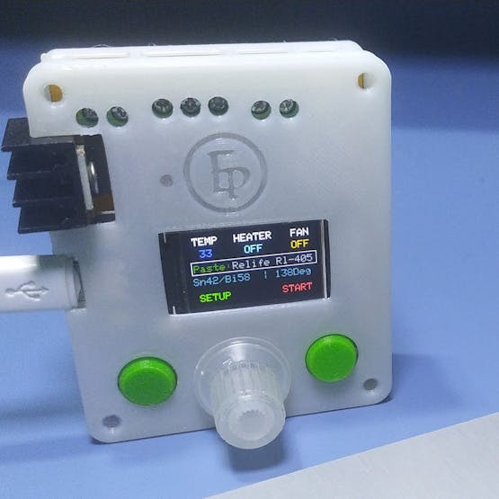
After powering it up we come to the home screen. Here we can see the current temperature, the heater and the fan states. Then we can choose the reflow profile from the paste option. In the setup we can see more options.
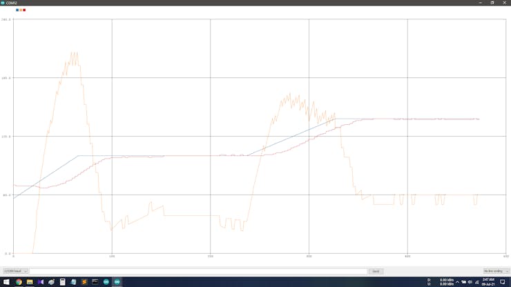
The reflow process starts when we press the start button. Here you can see the graph based on the reflow profile that we have set in the code. Then the heater starts and the PID algorithm starts controlling the temperature. The while line represents the current temperature and as you can see it pretty much follows the defined graph. So the PID works perfectly. I also 3d printed a case for the controller board and these little button caps. And after putting them on our project is complete.So it's time to reflow some PCBs.
Video :

Reflow Hotplate Controller
*PCBWay community is a sharing platform. We are not responsible for any design issues and parameter issues (board thickness, surface finish, etc.) you choose.

Raspberry Pi 5 7 Inch Touch Screen IPS 1024x600 HD LCD HDMI-compatible Display for RPI 4B 3B+ OPI 5 AIDA64 PC Secondary Screen(Without Speaker)
BUY NOW
ESP32-S3 4.3inch Capacitive Touch Display Development Board, 800×480, 5-point Touch, 32-bit LX7 Dual-core Processor
BUY NOW
Raspberry Pi 5 7 Inch Touch Screen IPS 1024x600 HD LCD HDMI-compatible Display for RPI 4B 3B+ OPI 5 AIDA64 PC Secondary Screen(Without Speaker)
BUY NOW- Comments(9)
- Likes(10)
-
 J j
Jan 28,2025
-
 Engineer
Aug 10,2024
-
 Engineer
Jun 12,2024
-
 Dino Canalli
Oct 15,2023
-
 Sebastian Mackowiak
Mar 21,2023
-
 Engineer
Jan 09,2023
-
 wbe
Oct 21,2022
-
 Manuel Conti
Apr 28,2022
-
 Engineer
Apr 20,2022
-
 Engineer
Aug 13,2021
- 0 USER VOTES
- YOUR VOTE 0.00 0.00
- 1
- 2
- 3
- 4
- 5
- 6
- 7
- 8
- 9
- 10
- 1
- 2
- 3
- 4
- 5
- 6
- 7
- 8
- 9
- 10
- 1
- 2
- 3
- 4
- 5
- 6
- 7
- 8
- 9
- 10
- 1
- 2
- 3
- 4
- 5
- 6
- 7
- 8
- 9
- 10
 More by SAYANTAN ElectroPoint4u
-
 How to make RGBW lights using Aluminium PCB
When it comes to making electronics projects, a custom PCB board is always one of the top priorities...
-
 ESP32 BLE GamePad
This is a DIY handheld gamepad, made using ESP32 microcontroller. You might have seen such game cont...
-
 12 Channel Ultimate Home Automation
ESP32 based 12 Channel IOT Home Automation using Blynk Application. Can be controlled using Physical...
-
 World's Slimmest NeoPixel LED Matrix
I always have this idea of what would have happened if we can put the components inside the pcb? Let...
-
 ESP-12E/F Breakout Board
Size:25.4mm x 30mmSignal Layers:2None Signal Layers:10Components:12Pads:57 Surface Pads:35 Plated Th...
-
 PCB Pyramid
In this project I built a rather interesting project which I thought a long time ago. Its basically ...
-
 3D printed Stepper Bot
This is a E.S.P32 based robot that I made which can not only be controlled over the internet but als...
-
 ESP32-C3 NodeMCU
This is a DropIn replacement for NodeMCU ESP8266 AMICA CP2102 WiFi Development Board. The pinout are...
-
 NeoPixel XL
What is it?If you ever been used or seen neopixel LED, then you will be familiar to this concept. It...
-
 ESP32 BLE Macro Keyboard
This is a wireless macro keyboard consist of 10 cherry MX key swathes with individual backlight. It ...
-
 DIY Novatrope
A DIY replica of the popular Novatrope project, an elegant kinetic kinetic sculpture using Attiny85,...
-
 Fanmade 7th Anniversary badge
This is a simple PCB badge that I designed for celebrate 7th anniversary of PCBway. It has 6 RGB bli...
-
 Reflow Hotplate Controller
Story :Last time I made a reflow soldering hotplate from a regular clothing iron. And it works prett...
-
 ESP Programmer
ESP8266 and ESP32 required some special arrangement to pull the chip into boot mode. Typically this ...
-
 Portable Power Supply for microcontroller projects
If you are working on a portable electronics project, or in a remote place where you can’t bring you...
-
 Pico Clock
StoryRaspberry Pi foundation recently launched their first microcontroller based development board R...
-
 Addressable Output using WS2811
So I was needed to control almost 200+ relays using one microcontroller and during research I found ...
-
 Portable wireless touch Remote
An ESP32 module comes with a lot of different features. One of such features is it’s touch capabilit...
-
 How to make RGBW lights using Aluminium PCB
When it comes to making electronics projects, a custom PCB board is always one of the top priorities...
-
 ESP32 BLE GamePad
This is a DIY handheld gamepad, made using ESP32 microcontroller. You might have seen such game cont...
-
 12 Channel Ultimate Home Automation
ESP32 based 12 Channel IOT Home Automation using Blynk Application. Can be controlled using Physical...
-
 World's Slimmest NeoPixel LED Matrix
I always have this idea of what would have happened if we can put the components inside the pcb? Let...
-
 ESP-12E/F Breakout Board
Size:25.4mm x 30mmSignal Layers:2None Signal Layers:10Components:12Pads:57 Surface Pads:35 Plated Th...
-
 PCB Pyramid
In this project I built a rather interesting project which I thought a long time ago. Its basically ...
-
 3D printed Stepper Bot
This is a E.S.P32 based robot that I made which can not only be controlled over the internet but als...
-
 ESP32-C3 NodeMCU
This is a DropIn replacement for NodeMCU ESP8266 AMICA CP2102 WiFi Development Board. The pinout are...
-
 NeoPixel XL
What is it?If you ever been used or seen neopixel LED, then you will be familiar to this concept. It...
-
 ESP32 BLE Macro Keyboard
This is a wireless macro keyboard consist of 10 cherry MX key swathes with individual backlight. It ...
-
 DIY Novatrope
A DIY replica of the popular Novatrope project, an elegant kinetic kinetic sculpture using Attiny85,...
-
 Fanmade 7th Anniversary badge
This is a simple PCB badge that I designed for celebrate 7th anniversary of PCBway. It has 6 RGB bli...
-
-
-
Modifying a Hotplate to a Reflow Solder Station
745 1 5 -
MPL3115A2 Barometric Pressure, Altitude, and Temperature Sensor
400 0 1 -
-
Nintendo 64DD Replacement Shell
350 0 2 -
V2 Commodore AMIGA USB-C Power Sink Delivery High Efficiency Supply Triple Output 5V ±12V OLED display ATARI compatible shark 100W
961 4 2 -
How to measure weight with Load Cell and HX711
636 0 3




Enclosure files updated
verry well, thank you
Hello me again, the Case is verry thin, do you share the CAD File for the Case to make it stronger ?, Thank you