|
|
Arduino Nano R3 |
x 1 | |
|
|
I2C 16x2 Arduino LCD Display Module |
x 1 | |
|
|
Low Current Sensor Breakout - ACS712 |
x 1 | |
|
|
Pushbutton Switch |
x 1 | |
|
|
solar cell 0.5V |
x 1 | |
|
|
Resistor, 5.1 kohm |
x 1 | |
|
|
Resistor 2.21k ohm |
x 1 |

|
arduino IDEArduino
|
|

|
Soldering Iron Kit |
Simple Arduino Solar Radiation Meter for Solar Panels
The sun provides more than enough energy to meet the whole world’s energy needs, and unlike fossil fuels, it won’t run out anytime soon. Solar power cell is are renewable CO2-free power source that convert Sunlight into Direct Current (DC) electricity. Solar irradiation is the power per unit area received from the Sun in the form of electromagnetic radiation, and is typically expressed in watts per square meter (W/m²). This data is used to determine the potential for solar power generation, and it helps in designing and optimizing solar panels and other solar energy systems.
The simplest way to measure solar radiation is to connect a low value resistor in parallel with the solar cell and measure the voltage drop across the resistor.

The current sensor module utilizing hall-effect principle which voltage is produced from the movement of current within the region of magnetic field. The voltage produced by hall effect is directly proportional to the applied current making it suitable to estimate the applied current from the voltage sensed.
This project was originally presented on the Solarduino site and all credit goes to them. On the site you can also find detailed instructions as well as links where you can get all the components. I made minor adjustments to the code based on the components I had at the time of building the device. Instead of a 16x2 LCD Display Shield I use a standard 16x2 LCD Display with a separate Initialization Button.

This project is sponsored by PCBWay(https://www.pcbway.com/?from=MirkoP ). They has all the services you need to create your project at the best price, whether is a scool project, or complex professional project. On PCBWay you can share your experiences, or get inspiration for your next project. They also provide completed Surface mount SMT PCB assemblY service at a best price, and ISO9001 quality control. Visit pcbway.com for more services.

The device is extremely simple to make and consists of only a few components:
- Arduino Nano microcontroller board
- Solar Cell (preferably with a voltage of 0.5V and a short-circuit current of 0.5 to 1 A) - If we do not have information about this value from the manufacturer, we can determine it with the following procedure: We connect the solar cell directly to the ammeter, and point it in the direction of the sun so that the light falls on it at an angle of 90 degrees. The current that is read at this moment is called Short circuit current. Then this value is entered into the code.

- ACS712 Current Sensor Module rated at 5A
- 16x2 LCD Display with I2C communication protocol
- Button
- and two resistors
The sensor is connected to the solar cell with relatively thick and short wires to avoid interference and losses. The voltage output of the board is connected to the power supply and the A1 analog input of the Arduino.
Now let's consider the way of working with the device as well as its functioning in real conditions.
Immediately after turning on the device, we need to cover the sensor and press the button, and after that, initialization and calibration of the sensor takes place, which lasts about 5 seconds, then the message "OFFSET DONE" appears briefly, so next we direct the cell towards the sun. Now, I will use this Lamp instead of Sun.

After that, the data obtained from the measurement is displayed:
- The first row shows the amount of current generated by the panel, and the current power delivered by a panel with an area of 1 square meter.
- The second row shows us how many Watt-hours are generated from the beginning, until the moment of reading.

In this way, knowing the number of sunny days during the year for a selected location, we can relatively accurately calculate how much electricity would be produced annually with a given area of solar panels. Now let's see how this would look outside in real sunlight exposure. As we can see, the energy generated depends significantly on the angle at which the sunlight is received. General rules for the physical placement of solar panels are that the vertical angle of the panels should be approximately the same as the Longitude of the given location, and the orientation should be South, but not magnetic South that the compass shows, but true South with calculated magnetic declination.
And finally a short conclusion.
This is a very cheap and simple to make, but extremely useful instrument, especially when designing such systems to simulate and provide feasibility study of a location or site whether it is viable to install Solar PhotoVoltage System

/* Irradiation meter using Solar Cell by Solarduino */

// Note :  Safety is very important when dealing with electricity. We take no responsibilities while you do it at your own risk.
// Note :  Irradiation meter is designed to measure and record the irradiation level for PV system performance check and feasibility study.
// Note :  Irradiation can measure and record (in SD card) instantaneous short circuit current (Isc) of panel, instantaneous Irradiation (W/m2) and daily Irradiation Energy in (W/m2/day)
// Note :  The daily Irradiation Energy is reset everyday or reset upon power outage (power supply to Arduino).
// Note :  The accuracy of the Irradiation is subject to the quality of user's solar cell and current module sensor.
// Note :  The Short Circuit Current of panel is recommended to be slightly lower or near the maximum range of current sensor for better accuracy results.
// Note :  The Irradiation is 100% subject to measured current and temperature coeffecient is neglected as it has almost negligible effect
// Note :  The temperature coefficient is neglected so that do not need additional temperature probe, furthermore 65 degree celcius under hot sun (40 degree temperature diference from STC) only performing 2.5% difference.
// Note :  The unit provides reasonable accuracy and may not be comparable with other expensive branded and commercial irradiation meter.
// Note :  All credit shall be given to Solarduino.

/*/////////////////////////////////////////////////////////////////////////////////////////////////////////////////////////////////////////////////////////////////////////////////////*/


        /* 0- General */

        int decimalPrecision = 2;                   /* decimal places for only for current value shown in LED Display */

        /* 1- DC Current & Irradiation */

        int CurrentAnalogInputPin = A1;             // Which pin to measure Current Value
        float mVperAmpValue = 185;                  // If using ACS712 current module : for 5A module key in 185, for 20A module key in 100, for 30A module key in 66
                                                    // If using WCS current module : for 0.25A module key in 7000, for 0.5A module key in 3500, for 1.0A module key in 2000, for 2.0A module key in 1000.
        float moduleMiddleVoltage = 2500;           // key in middle voltage value in mV. For 5V power supply key in 2500, for 3.3V power supply, key in 1650 mV
        float moduleSupplyVoltage = 5000;           // supply voltage to current sensor module in mV, default 5000mV, may use 3300mV
        float currentSampleRead  = 0;               /* to read the value of a sample*/
        float currentLastSample  = 0;               /* to count time for each sample. Technically 1 milli second 1 sample is taken */
        float currentSampleSum   = 0;               /* accumulation of sample readings */
        float currentSampleCount = 0;               /* to count number of sample. */
        float currentMean ;                         /* to calculate the average value from all samples*/
        float finalCurrent ;                        /* the final current reading without taking offset value*/
        float finalCurrent2 ;                       /* the final current reading*/
        float ShortCircuitCurrentSTC = 1.2   ;      // Key in the Short Circuit Current (At STC condition) of your Solar Panel or Solar Cell. Value 9 showing 9.0A Isc Panel.
        float Irradiation = 0.00;                   /* This shows the irradiation level in W/m2.

            /* 1.1 - Offset DC Current */
            int   OffsetRead = 0;                   /* To switch between functions for auto callibation purpose */
            float currentOffset =0.00;              // to Offset deviation and accuracy. Offset any fake current when no current operates.
                                                    // the offset will automatically done when you press the <SELECT> button on the LCD display module.
                                                    // you may manually set offset here if you do not have LCD shield
            float offsetLastSample = 0;             /* to count time for each sample. Technically 1 milli second 1 sample is taken */
            float offsetSampleCount = 0;            /* to count number of sample. */

            /* 1.2 - Average Accumulate Irradiation */

            float accumulateIrradiation = 0;                          /* Amount of accumulate irradiation*/
            unsigned long startMillisIrradiation;                     /* start counting time for irradiation energy */
            unsigned long currentMillisIrradiation;                   /* current counting time for irradiation energy */
            const unsigned long periodIrradiation = 1000;             // refresh every X seconds (in seconds) Default 1000 = 1 second
            float FinalAccumulateIrradiationValue = 0;                /* shows the final accumulate irradiation reading*/


        /* 2 - LCD Display  */

    //    #include<LiquidCrystal.h>                                   /*Load the liquid Crystal Library (by default already built-it with arduino solftware)*/
    //   LiquidCrystal LCD(8,9,4,5,6,7);                             /*Creating the LiquidCrystal object named LCD */

       #include <Wire.h>

       #include <LiquidCrystal_I2C.h>
       LiquidCrystal_I2C LCD(0x27, 16, 2);


        unsigned long startMillisLCD;                               /* start counting time for LCD Display */
        unsigned long currentMillisLCD;                             /* current counting time for LCD Display */
        const unsigned long periodLCD = 1000;                       // refresh every X seconds (in seconds) in LED Display. Default 1000 = 1 second


void setup()

{

        /* 0- General */

        Serial.begin(9600);                               /* In order to see value in serial monitor */

        /* 1.2 - Average Accumulate Irradiation */

        startMillisIrradiation = millis();                /* Record initial starting time for daily irradiation */

        /* 2 - LCD Display  */

        LCD.begin(16,2);                                  /* Tell Arduino that our LCD has 16 columns and 2 rows*/
        LCD.backlight();
        LCD.clear();
        LCD.setCursor(5, 0);
        LCD.print("ARDUINO");
        LCD.setCursor(2, 1);
        LCD.print("IRRAD. METER");
        delay(3000);                             /* Set LCD to upper left corner to start display*/

        startMillisLCD = millis();                        /* Record initial starting time for LCD Display refresh rate. */

}

void loop()

{

  /* 0.1- Button Function */

              int buttonRead;
              buttonRead = analogRead (0);                                    // Read analog pin A0. By default the LCD Display shield already assigned A0 as button function. Cannot change.

           if (buttonRead < 800)
              {
              OffsetRead = 1;                                                 // to activate offset when button <SELECT> is pressed
              LCD.setCursor(0,0);
              LCD.print ("INITIALIZING..... ");
              LCD.setCursor(0,1);
              LCD.print ("WAIT 5 SEC ..... ");
             // delay(2000);
              }


  /* 1- DC Current & Irradiation */

        if(millis() >= currentLastSample + 1 )                                                                /* every 1 milli second taking 1 reading */
          {
            currentSampleRead = analogRead(CurrentAnalogInputPin)-((moduleMiddleVoltage/moduleSupplyVoltage)*1024);      /* read the sample value */
            currentSampleSum = currentSampleSum + currentSampleRead ;                                         /* accumulate value with older sample readings*/
            currentSampleCount = currentSampleCount + 1;                                                      /* to move on to the next following count */
            currentLastSample = millis();                                                                     /* to reset the time again so that next cycle can start again*/
          }

        if(currentSampleCount == 1000)                                                                        /* after 1000 count or 1000 milli seconds (1 second), do the calculation and display value*/
          {
            currentMean = currentSampleSum/currentSampleCount;                                                /* calculate average value of all sample readings taken*/
            finalCurrent = (((currentMean /1024)*moduleSupplyVoltage)/mVperAmpValue);                         /* calculate the final current (without offset)*/
            finalCurrent2 = finalCurrent+currentOffset;                                                       /* The final current */
            Irradiation = (finalCurrent2/ShortCircuitCurrentSTC*1000);
            Serial.print(finalCurrent2,decimalPrecision);
            Serial.print(" A  ");
            Serial.print(Irradiation,decimalPrecision);
            Serial.print(" W/m2  ");
            currentSampleSum =0;                                                                              /* to reset accumulate sample values for the next cycle */
            currentSampleCount=0;                                                                             /* to reset number of sample for the next cycle */
          }


            /* 1.1 - Offset DC Current */

            if(OffsetRead == 1)
              {
                currentOffset = 0;                                                             /* set back currentOffset as default first*/
                if(millis() >= offsetLastSample + 1)                                           /* offset 1 - to centralise analogRead waveform*/
                  {
                    offsetSampleCount = offsetSampleCount + 1;
                    offsetLastSample = millis();
                  }

                   if(offsetSampleCount == 2500)                                             /* need to wait awhile as to get new value before offset take into calculation.  */
                {                                                                             /* So this code is to delay 2.5 seconds after button pressed */
                  currentOffset = - finalCurrent;                                             /* to offset values */
                  OffsetRead = 0;                                                             /* until next offset button is pressed*/
                  offsetSampleCount = 0;                                                      /* to reset the time again so that next cycle can start again */
                  LCD.setCursor(0,0);
                  LCD.print ("OFFSET.....     ");
                  LCD.setCursor(0,1);
                  LCD.print ("DONE  .....     ");
                  delay(1000);
                }
            }


         /* 1.2 - Average Accumulate Irradiation */

         currentMillisIrradiation = millis();                                                                 /* Count the time for current */

        if (currentMillisIrradiation - startMillisIrradiation >= periodIrradiation)
        {
            accumulateIrradiation = Irradiation/3600*(periodIrradiation/1000);                                /* for smoothing calculation*/
            FinalAccumulateIrradiationValue =  FinalAccumulateIrradiationValue + accumulateIrradiation ;
            Serial.print(FinalAccumulateIrradiationValue,decimalPrecision);
            Serial.println(" Wh/m2/day");
            startMillisIrradiation = currentMillisIrradiation ;                                               /* Set the starting point again for next counting time */
        }


        /* 2 - LCD Display  */

        currentMillisLCD = millis();
        if (currentMillisLCD - startMillisLCD >= periodLCD)
          {
            LCD.setCursor(0,0);                                                                           /* Set cursor to first colum 0 and second row 1  */
            LCD.print(finalCurrent2,decimalPrecision);                                                    /* display voltage value in LCD in first row  */
            LCD.print(" A   ");
            LCD.setCursor(8,0);
            LCD.print(Irradiation,0);                                                                     /* display current value in LCD in first row */
            LCD.print(" W/m2   ");
            LCD.setCursor(0,1);
            LCD.print(FinalAccumulateIrradiationValue,0);                                                 /* display current value in LCD in first row */
            LCD.print("  Wh/m2   ");
            startMillisLCD = currentMillisLCD ;                                                           /* Set the starting point again for next counting time */
          }
}

Simple Arduino Solar Radiation Meter for Solar Panels
- Comments(0)
- Likes(0)
- 0 USER VOTES
- YOUR VOTE 0.00 0.00
- 1
- 2
- 3
- 4
- 5
- 6
- 7
- 8
- 9
- 10
- 1
- 2
- 3
- 4
- 5
- 6
- 7
- 8
- 9
- 10
- 1
- 2
- 3
- 4
- 5
- 6
- 7
- 8
- 9
- 10
- 1
- 2
- 3
- 4
- 5
- 6
- 7
- 8
- 9
- 10
 More by Mirko Pavleski
-
 Arduino 3D Printed self Balancing Cube
Self-balancing devices are electronic devices that use sensors and motors to keep themselves balanc...
-
 DIY 5-Day Rainfall Forecast Device - ESP32 E-Paper Project
In several of my previous projects I have presented ways to make weather stations, but this time I ...
-
 Build simple Retro Style VFO (Variable frequency oscillator) with Crowoanel 1.28 inch Round Display
Today I received a shipment with a Small round LCD display from Elecrow. The device is packed in tw...
-
 Human vs Robot – Rock Paper Scissors with MyCobot 280 M5Stack
Today I received a package containing the few Elephant Robotics products. The shipment is well pack...
-
 How to Build a Simple Audio Spectrum Analyzer with Adjustable Settings
An audio spectrum analyzer is an electronic device or software tool that measures and visually disp...
-
 How to Make a Digital Clock on a Vintage B&W TV using Arduino
These days I accidentally came across this small retro Black and White TV with a built-in Radio, so ...
-
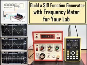 Build a $10 Function Generator with Frequency Meter for Your Lab
A function generator is a piece of electronic test equipment used to generate various types of elec...
-
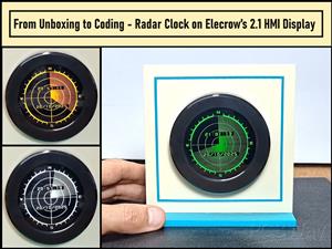 From Unboxing to Coding - Radar Clock on Elecrow’s 2.1 HMI Display
Today I received a shipment with a large round LCD display from Elecrow. The device is packed in two...
-
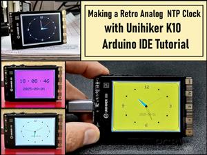 Making a Retro Analog NTP Clock with Unihiker K10 - Arduino IDE Tutorial
Some time ago I presented you a way to use standard Arduino libraries on the Unihiker k10 developme...
-
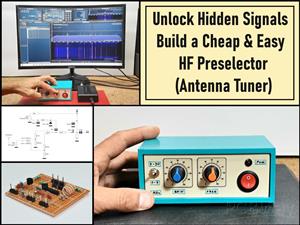 Build a Cheap & Easy HF Preselector - Antenna Tuner
HF antenna preselector is an electronic device connected between an HF radio antenna, and a radio r...
-
 DIY Static Charge Monitor - Electrostatic Field Detector (Arduino & TL071)
A Static Charge Monitor also known as a Static Field Meter or Electrostatic Voltmeter is a device u...
-
 XHDATA D-219 Radio Short Review with complete disassembly
Some time ago I received an offer from XHDATA to be one of the first test users of their new radio m...
-
 How to make Simplest ever Oscilloscope Clock
An oscilloscope clock is a unique and creative way to display the time using an oscilloscope, which...
-
 DIY Digital Barograph with BME280 and ESP32 - 24 Hour Pressure Trends
A barograph is a self-recording barometer that continuously measures and records atmospheric pressu...
-
 Build a Raspberry Pi Pico SDR Radio with Waterfall Display
Software-defined radio (SDR) is a radio communication system where components that have traditional...
-
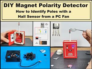 DIY Magnet Polarity Detector - How to Identify Poles with a Hall Sensor from a PC Fan
Recently, while working on a project, I needed to determine the polarity of several permanent magne...
-
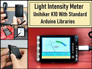 Light Meter Project - Making Dfrobot Unihiker K10 Work with Standard Arduino Libraries
The other day I received a shipment with a UNIHIKER K10 development board from DFRobot, which I rec...
-
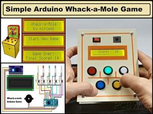 DIY Simple Arduino Whack-a-Mole Game
A "Whack-a-Mole" game is a classic arcade-style game where moles pop up randomly from holes, and th...
-
-
AEL-2011 Power Supply Module
525 0 2 -
AEL-2011 50W Power Amplifier
485 0 2 -
-
-
Custom Mechanical Keyboard
693 0 0 -
Tester for Touch Screen Digitizer without using microcontroller
330 2 2 -
Audio reactive glow LED wristband/bracelet with NFC / RFID-Tags
310 0 1 -
-
-


