|
A000066Arduino
|
x 1 | |

|
NEO-6M-0u-blox
|
x 1 | |

|
Mini Breadboard |
x 1 | |

|
40 Pin Jumper Wires Female to Female 20cm |
x 1 |

|
arduino IDEArduino
|
Arduino Location Tracker
Introducing the NEO-6M GPS Module
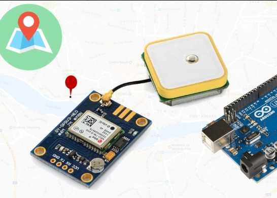
The NEO-6M GPS module is shown in the figure below. It comes with an external antenna, and does’t come with header pins. So, you’ll need to get and solder some.

This module has an external antenna and built-in EEPROM.
Interface: RS232 TTL
Power supply: 3V to 5V
Default baudrate: 9600 bps
Works with standard NMEA sentences
The NEO-6M GPS module is also compatible with other microcontroller boards. To learn how to use the NEO-6M GPS module with the Raspberry Pi, you can read: Email Alert System on Location Change with Raspberry Pi and GPS Module.
Pin Wiring
The NEO-6M GPS module has four pins: VCC, RX, TX, and GND. The module communicates with the Arduino via serial communication using the TX and RX pins, so the wiring couldn’t be simpler:
NEO-6M GPS ModuleWiring to Arduino UNOVCC5VRXTX pin defined in the software serialTXRX pin defined in the software serialGNDGND
Getting GPS Raw Data
To get raw GPS data you just need to start a serial communication with the GPS module using Software Serial. Continue reading to see how to do that.
Parts Required
For testing this example you’ll need the following parts:
Arduino – read Best Arduino Starter Kits
NEO-6M GPS module
Jumper wires
Schematics
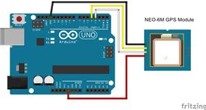
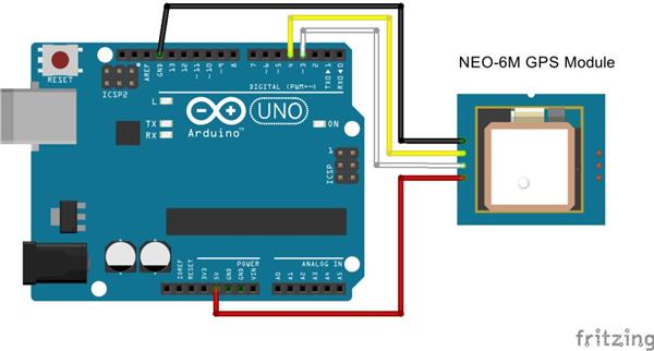
Wire the NEO-6M GPS module to your Arduino by following the schematic below.

The module GND pin is connected to Arduino GND pin
The module RX pin is connected to Arduino pin 3
The module TX pin is connected to Arduino pin 4
The module VCC pin is connected to Arduino 5V pin
#include <SoftwareSerial.h>
// The serial connection to the GPS module
SoftwareSerial ss(4, 3);
void setup(){
Serial.begin(9600);
ss.begin(9600);
}
void loop(){
while (ss.available() > 0){
// get the byte data from the GPS
byte gpsData = ss.read();
Serial.write(gpsData);
}
}
View raw code
This sketch assumes you are using pin 4 and pin 3 as RX and TX serial pins to establish serial communication with the GPS module. If you’re using other pins you should edit that on the following line:
SoftwareSerial ss(4, 3);
Also, if your module uses a different default baud rate than 9600 bps, you should modify the code on the following line:
ss.begin(9600);
This sketch listen to the GPS serial port, and when data is received from the module, it is sent to the serial monitor.
while (ss.available() > 0){
// get the byte data from the GPS
byte gpsData = ss.read();
Serial.write(gpsData);
}
Open the Serial Monitor at a baud rate of 9600.

Understanding NMEA Sentences
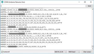
NMEA sentences start with the $ character, and each data field is separated by a comma.
$GPGGA,110617.00,41XX.XXXXX,N,00831.54761,W,1,05,2.68,129.0,M,50.1,M,,*42
$GPGSA,A,3,06,09,30,07,23,,,,,,,,4.43,2.68,3.53*02
$GPGSV,3,1,11,02,48,298,24,03,05,101,24,05,17,292,20,06,71,227,30*7C
$GPGSV,3,2,11,07,47,138,33,09,64,044,28,17,01,199,,19,13,214,*7C
$GPGSV,3,3,11,23,29,054,29,29,01,335,,30,29,167,33*4E
$GPGLL,41XX.XXXXX,N,00831.54761,W,110617.00,A,A*70
$GPRMC,110618.00,A,41XX.XXXXX,N,00831.54753,W,0.078,,030118,,,A*6A
$GPVTG,,T,,M,0.043,N,0.080,K,A*2C
There are different types of NMEA sentences. The type of message is indicated by the characters before the first comma.
The GP after the $ indicates it is a GPS position. The $GPGGA is the basic GPS NMEA message, that provides 3D location and accuracy data. In the following sentence:
$GPGGA,110617.00,41XX.XXXXX,N,00831.54761,W,1,05,2.68,129.0,M,50.1,M,,*42
110617 – represents the time at which the fix location was taken, 11:06:17 UTC
41XX.XXXXX,N – latitude 41 deg XX.XXXXX’ N
00831.54761,W – Longitude 008 deg 31.54761′ W
1 – fix quality (0 = invalid; 1= GPS fix; 2 = DGPS fix; 3 = PPS fix; 4 = Real Time Kinematic; 5 = Float RTK; 6 = estimated (dead reckoning); 7 = Manual input mode; 8 = Simulation mode)
05 – number of satellites being tracked
2.68 – Horizontal dilution of position
129.0, M – Altitude, in meters above the sea level
50.1, M – Height of geoid (mean sea level) above WGS84 ellipsoid
empty field – time in seconds since last DGPS update
empty field – DGPS station ID number
*42 – the checksum data, always begins with *
The other NMEA sentences provide additional information:
$GPGSA – GPS DOP and active satellites
$GPGSV – Detailed GPS satellite information
$GPGLL – Geographic Latitude and Longitude
$GPRMC – Essential GPS pvt (position, velocity, time) data
$GPVTG – Velocity made good
To know what each data field means in each of these sentences, you can consult NMEA data here.
Parsing NMEA Sentences with TinyGPS++ Library
You can work with the raw data from the GPS, or you can convert those NMEA messages into a readable and useful format, by saving the characters sequences into variables. To do that, we’re going to use the TinyGPS++ library.
This library makes it simple to get information on location in a format that is useful and easy to understand. You can click here for more information about the TinyGPS++ Library.
Installing the TinyGPS++ Library
Follow the next steps to install the TinyGPS++ library in your Arduino IDE:
Click here to download the TinyGPSPlus library. You should have a .zip folder in your Downloads folder
Unzip the .zip folder and you should get TinyGPSPlus-master folder
Rename your folder from TinyGPSPlus-master to TinyGPSPlus
Move the TinyGPSPlus folder to your Arduino IDE installation libraries folder
Finally, re-open your Arduino IDE
The library provides several examples on how to use it. In your Arduino IDE, you just need to go to File > Examples > TinyGPS++, and choose from the examples provided.
Note: the examples provided in the library assume a baud rate of 4800 for the GPS module. You need to change that to 9600 if you’re using the NEO-6M GPS module.
Getting Location Using the NEO-6M GPS Module and the TinyGPS++ Library
You can get the location in a format that is convenient and useful by using the TinyGPS++ library. Below, we provide a code to get the location from the GPS. This is a simplified version of one of the library examples.
#include <TinyGPS++.h>
#include <SoftwareSerial.h>
static const int RXPin = 4, TXPin = 3;
static const uint32_t GPSBaud = 9600;
// The TinyGPS++ object
TinyGPSPlus gps;
// The serial connection to the GPS device
SoftwareSerial ss(RXPin, TXPin);
void setup(){
Serial.begin(9600);
ss.begin(GPSBaud);
}
void loop(){
// This sketch displays information every time a new sentence is correctly encoded.
while (ss.available() > 0){
gps.encode(ss.read());
if (gps.location.isUpdated()){
Serial.print("Latitude= ");
Serial.print(gps.location.lat(), 6);
Serial.print(" Longitude= ");
Serial.println(gps.location.lng(), 6);
}
}
}
View raw code
You start by importing the needed libraries: TinyGPSPlus and SoftwareSerial
#include <TinyGPS++.h>
#include <SoftwareSerial.h>
Then, you define the software serial RX and TX pins, as well as the GPS baud rate. If you are using other pins for software serial you need to change that here. Also, if your GPS module uses a different default baud rate, you should also modify that.
static const int RXPin = 4, TXPin = 3;
static const uint32_t GPSBaud = 9600;
Then, you create a TinyGPS++ object:
TinyGPSPlus gps;
And start a serial connection on the pins you’ve defined earlier
SoftwareSerial ss(RXPin, TXPin);
In the setup(), you initialize serial communication, both to see the readings on the serial monitor and to communicate with the GPS module.
void setup() {
Serial.begin(9600);
ss.begin(GPSBaud);
}
In the loop is where you request the information. To get TinyGPS++ to work, you have to repeatedly funnel the characters to it from the GPS module using the encode() method.
while (ss.available() > 0){
gps.encode(ss.read());
Then, you can query the gps object to see if any data fields have been updated:
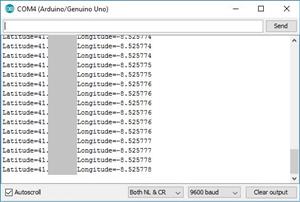
if (gps.location.isUpdated()){
Serial.print("Latitude="); Serial.print(gps.location.lat(), 6);
Serial.print("Longitude="); Serial.println(gps.location.lng(), 6);
}
Getting the latitude and longitude is has simple has using gps.location.lat(), and gps.location.lng(), respectively.
Arduino Location Tracker

Raspberry Pi 5 7 Inch Touch Screen IPS 1024x600 HD LCD HDMI-compatible Display for RPI 4B 3B+ OPI 5 AIDA64 PC Secondary Screen(Without Speaker)
BUY NOW
ESP32-S3 4.3inch Capacitive Touch Display Development Board, 800×480, 5-point Touch, 32-bit LX7 Dual-core Processor
BUY NOW
Raspberry Pi 5 7 Inch Touch Screen IPS 1024x600 HD LCD HDMI-compatible Display for RPI 4B 3B+ OPI 5 AIDA64 PC Secondary Screen(Without Speaker)
BUY NOW- Comments(0)
- Likes(2)
 Log in to post comments.
-
 Sebastian Mackowiak
Mar 21,2023
-
 Engineer
Sep 28,2022
- 0 USER VOTES
- YOUR VOTE 0.00 0.00
- 1
- 2
- 3
- 4
- 5
- 6
- 7
- 8
- 9
- 10
- 1
- 2
- 3
- 4
- 5
- 6
- 7
- 8
- 9
- 10
- 1
- 2
- 3
- 4
- 5
- 6
- 7
- 8
- 9
- 10
- 1
- 2
- 3
- 4
- 5
- 6
- 7
- 8
- 9
- 10
 More by Engineer
-
 Motion Detection Alarm
ABOUT THIS PROJECTIn this project we’ll modify a commercial motion sensor (powered with mains voltag...
-
 Iot Spirit Level
ABOUT THIS PROJECTThe gyroscope measures rotational velocity (rad/s), this is the change of the angu...
-
 PIR Night Security Light
Parts Required:Here’s a list of the parts needed for this project:PIR Motion Sensor 220V (or 110V PI...
-
 Arduino Temperature Logger With Sd Card
Parts requiredHere’s a complete list of the parts required for this project:Arduino UNO – read Best ...
-
 Arduino Location Tracker
Introducing the NEO-6M GPS ModuleThe NEO-6M GPS module is shown in the figure below. It comes with a...
-
 Attendance System With Arduino & Rfid Tag
MFRC522 RFID ReaderIn this project we’re using the MFRC522 RFID reader and that’s the one we recomme...
-
 Esp8266 Task Publisher
In this project you’re going to build an ESP8266 Wi-Fi Button that can trigger any home automation e...
-
 ESP32 Avanced Weather Station
Introducing the BME280 Sensor ModuleThe BME280 sensor module reads temperature, humidity, and pressu...
-
 Esp32 Pir Sensor Time Interrupts
Introducing InterruptsTo trigger an event with a PIR motion sensor, you use interrupts. Interrupts a...
-
 Multiple Temperature Sensor Data Logging With Esp32
Introducing the DS18B20 Temperature SensorThe DS18B20 temperature sensor is a 1-wire digital tempera...
-
 IOT Button
IFTTTFor this project we’re going to use a free service called IFTTT that stands for If This Than Th...
-
 Wemos D1 Multishield Arduino
Project OverviewThe shield consists of a temperature sensor, a motion sensor, an LDR, and a 3 pin so...
-
 Motion Detection Alarm
ABOUT THIS PROJECTIn this project we’ll modify a commercial motion sensor (powered with mains voltag...
-
 Iot Spirit Level
ABOUT THIS PROJECTThe gyroscope measures rotational velocity (rad/s), this is the change of the angu...
-
 PIR Night Security Light
Parts Required:Here’s a list of the parts needed for this project:PIR Motion Sensor 220V (or 110V PI...
-
 Arduino Temperature Logger With Sd Card
Parts requiredHere’s a complete list of the parts required for this project:Arduino UNO – read Best ...
-
 Arduino Location Tracker
Introducing the NEO-6M GPS ModuleThe NEO-6M GPS module is shown in the figure below. It comes with a...
-
 Attendance System With Arduino & Rfid Tag
MFRC522 RFID ReaderIn this project we’re using the MFRC522 RFID reader and that’s the one we recomme...
-
 Esp8266 Task Publisher
In this project you’re going to build an ESP8266 Wi-Fi Button that can trigger any home automation e...
-
 ESP32 Avanced Weather Station
Introducing the BME280 Sensor ModuleThe BME280 sensor module reads temperature, humidity, and pressu...
-
 Esp32 Pir Sensor Time Interrupts
Introducing InterruptsTo trigger an event with a PIR motion sensor, you use interrupts. Interrupts a...
-
 Multiple Temperature Sensor Data Logging With Esp32
Introducing the DS18B20 Temperature SensorThe DS18B20 temperature sensor is a 1-wire digital tempera...
-
 IOT Button
IFTTTFor this project we’re going to use a free service called IFTTT that stands for If This Than Th...
-
 Wemos D1 Multishield Arduino
Project OverviewThe shield consists of a temperature sensor, a motion sensor, an LDR, and a 3 pin so...
-
-
Commodore 64 1541-II 1581 Floppy Disk Drive C64 Power Supply Unit USB-C 5V 12V DIN connector 5.25
167 1 3 -
Easy to print simple stacking organizer with drawers
87 0 0 -
-
-
-
Modifying a Hotplate to a Reflow Solder Station
1137 1 6 -
MPL3115A2 Barometric Pressure, Altitude, and Temperature Sensor
639 0 1 -
-
Nintendo 64DD Replacement Shell
495 0 2 -
V2 Commodore AMIGA USB-C Power Sink Delivery High Efficiency Supply Triple Output 5V ±12V OLED display ATARI compatible shark 100W
1442 4 3


