|
|
Male Header, 2.54mm 1x20pin |
x 3 | |
|
|
Male Header, 2.54mm 1x19pin |
x 1 |
ESP32-S DEV Prototype Shield
Easy to use ESP32-S DEV Prototype Shield
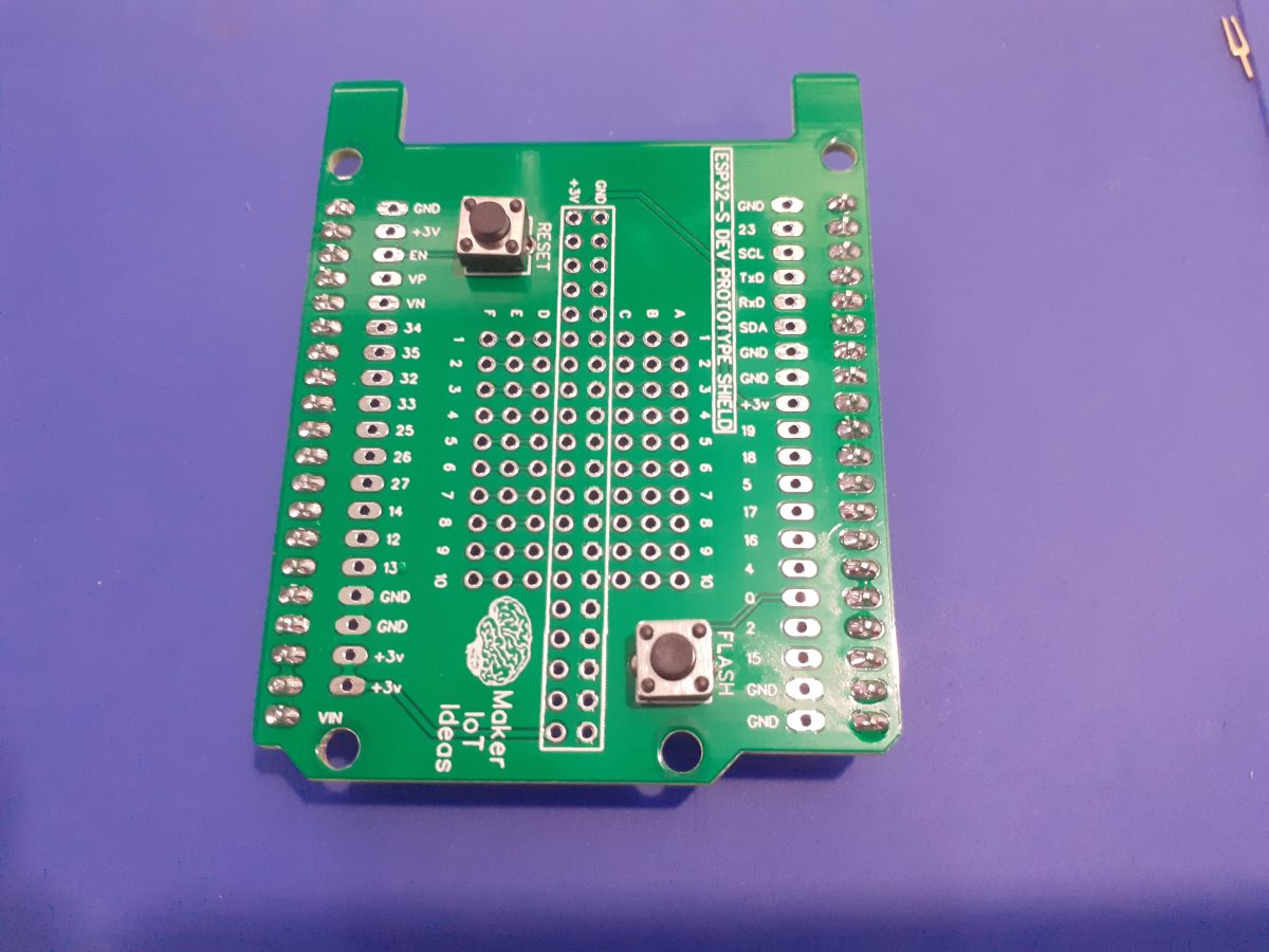
While my recent ESP32-S Dev Board really does the trick to help my development cycle along, I very quickly ran into another obstacle, in the sense that, after doing stuff on the breadboard, moving those components onto a more permanent location, either as a next stage prototype or more likely that the project is so small and insignificant not to warrant the effort actually to design a PCB for it. This could be rectified by using another one of my recent designs, an SMD breadboard PCB, but that would not always do either.
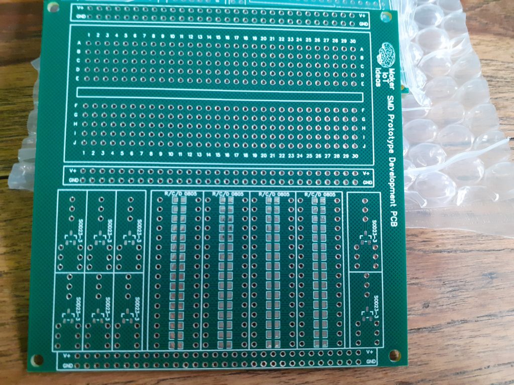 MakerIoT SMD Prototype development PCB
That got me thinking, and while staring at the ever-present Arduino Uno on its corner of the work-bench, I suddenly remembered that I have once seen an Arduino Prototype Shield, like a plug-on breadboard, with breakouts of all the pins etc…
While I do not personally own a lot of commercial Arduino Shields, as I tend to build my own or design a custom-purpose PCB instead, it did not take me long to settle on a new design, that could potentially solve my problem, and hopefully, someone else’s as well…
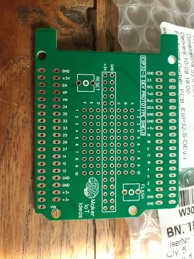
So what is on this PCB?
To start off, the PCB is in the same form factor as the ESP32-S Dev Board, namely the Arduino Uno form factor. There are however a few changes, mainly in the number of pins in the headers. This is mainly to accommodate as many of the ESP32-S's gpios as possible. ( Actually, they are all broken out, EXCEPT for the 6 gpio's that are usually used with the internal Flash memory.)
The PCB is designed to be stacked either on top of or even below, the ESP32-S Dev Board, depending of course on the type of headers that you decide to solder onto the PCB.
In order to make connecting to the gpio pins easier, each header row is in fact a double row, with solderable pads in parallel for each gpio on the header row.
Flash and Reset buttons are available on top of the shield, they can be fitted of left off, depending on personal preference, as well as how the shield will ultimately be used.
The prototyping area in the centre has been slightly reduced from the standard 5-pin-spacer-5-pin column of the traditional breadboard to a 3-pin-gnd-3v-3-pin column layout. the prototyping holes are at a standard 0.1" or 2.54mm pitch.
In total, 60 prototype holes, divided into rows of 10, 3 columns deep, are provided, labelled A-F and 1-10.
3.3v and ground are provided in the center two rows, to make power easily accesible.
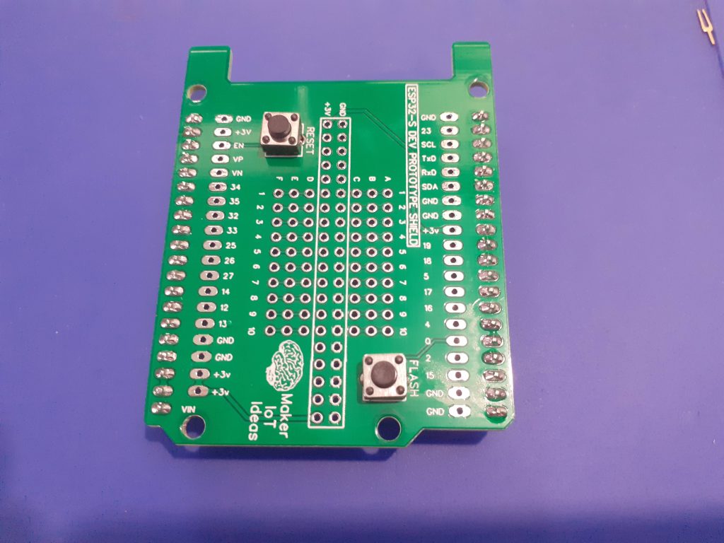 ESP32-S DEV Prototype Shield
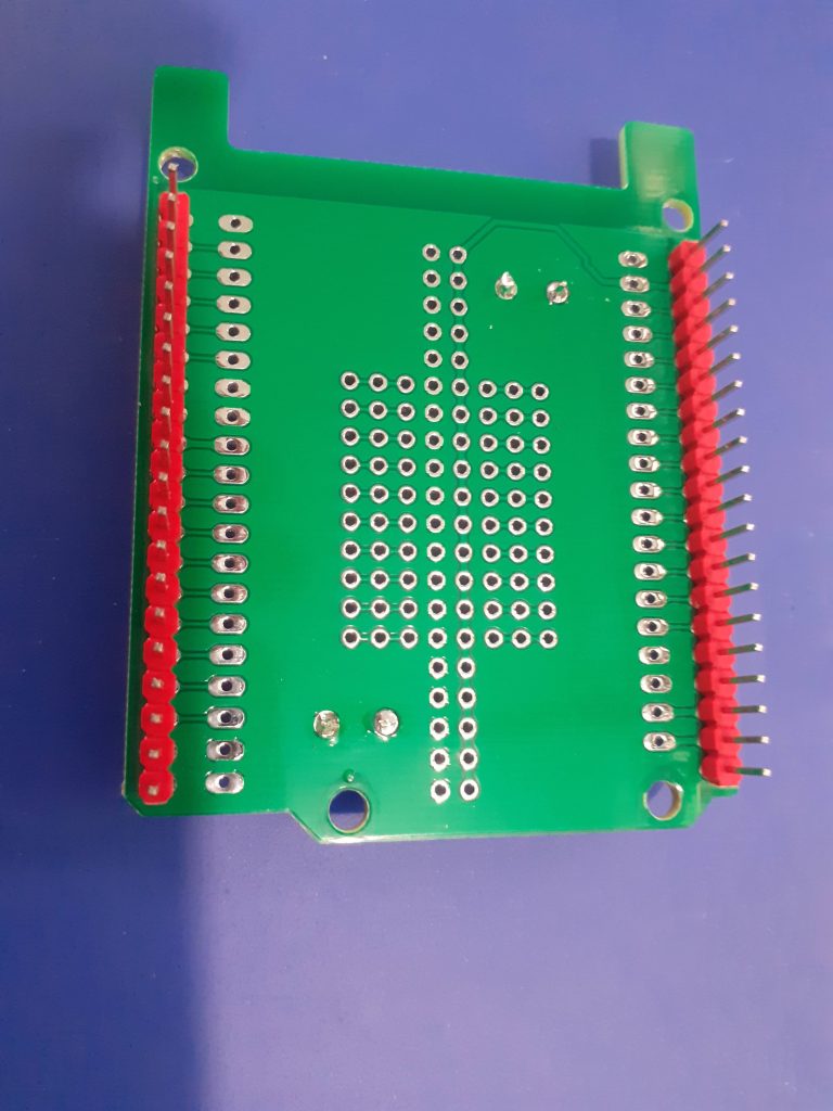 ESP32-S Dev Prototype Shield - Back
The PCB Design
As this design is basically just two rows of header pins, with a few switches, and a big unconnected prototype area, I did not bother to do a formal schematic for this PCB, but instead jumped straight into the PCB design software and manually designed and routed the tracks and pads that make up this shield.

PCB - Top Layer

PCB - Bottom Layer - Note that this is a "TOP-Down" view, and should be mirrored for actual production
Note that there are big copper pours on both the top and bottom layers, in an attempt to reduce electrical noise and provide better shielding.
Some more pictures of the device
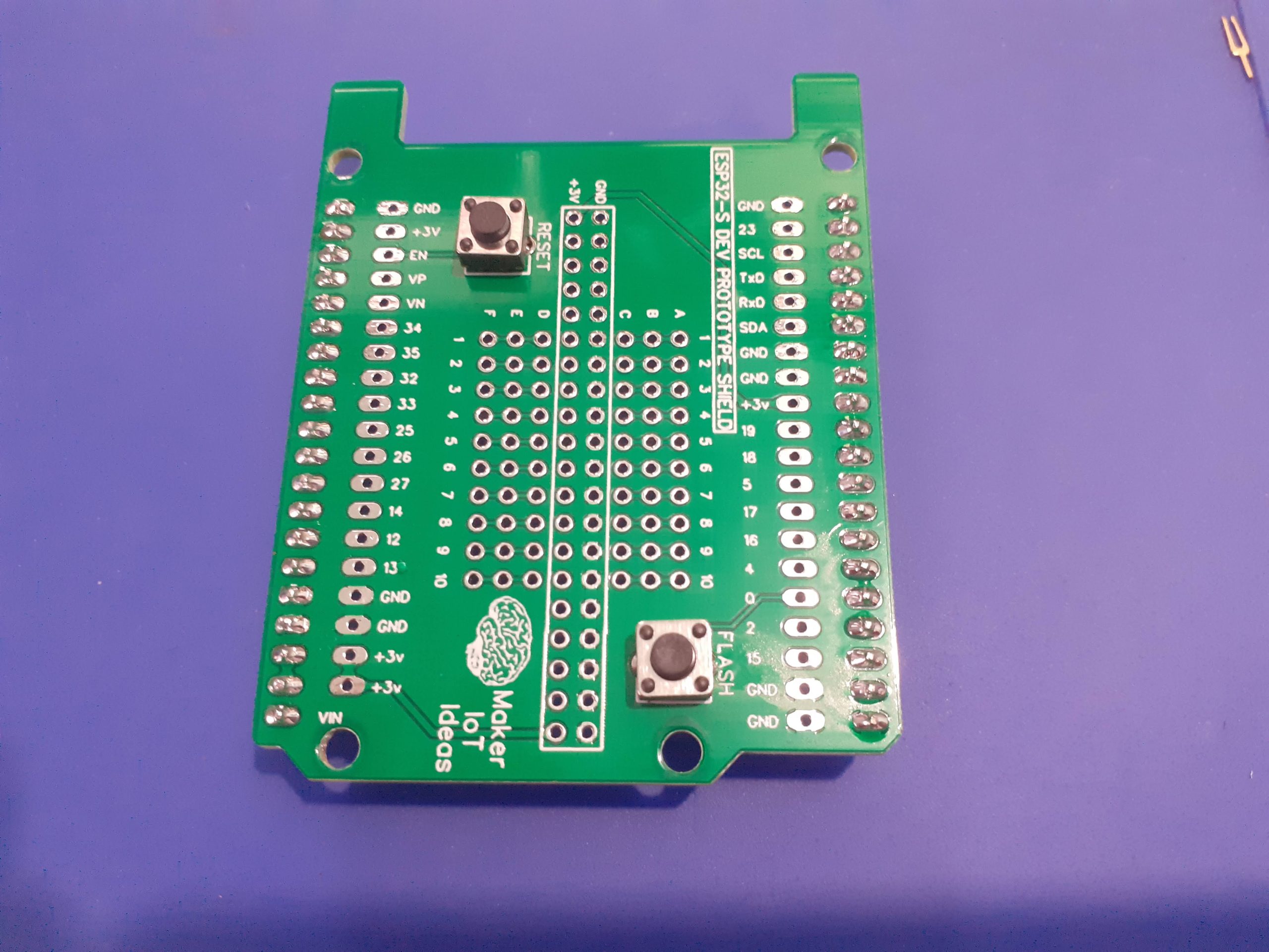 Top view
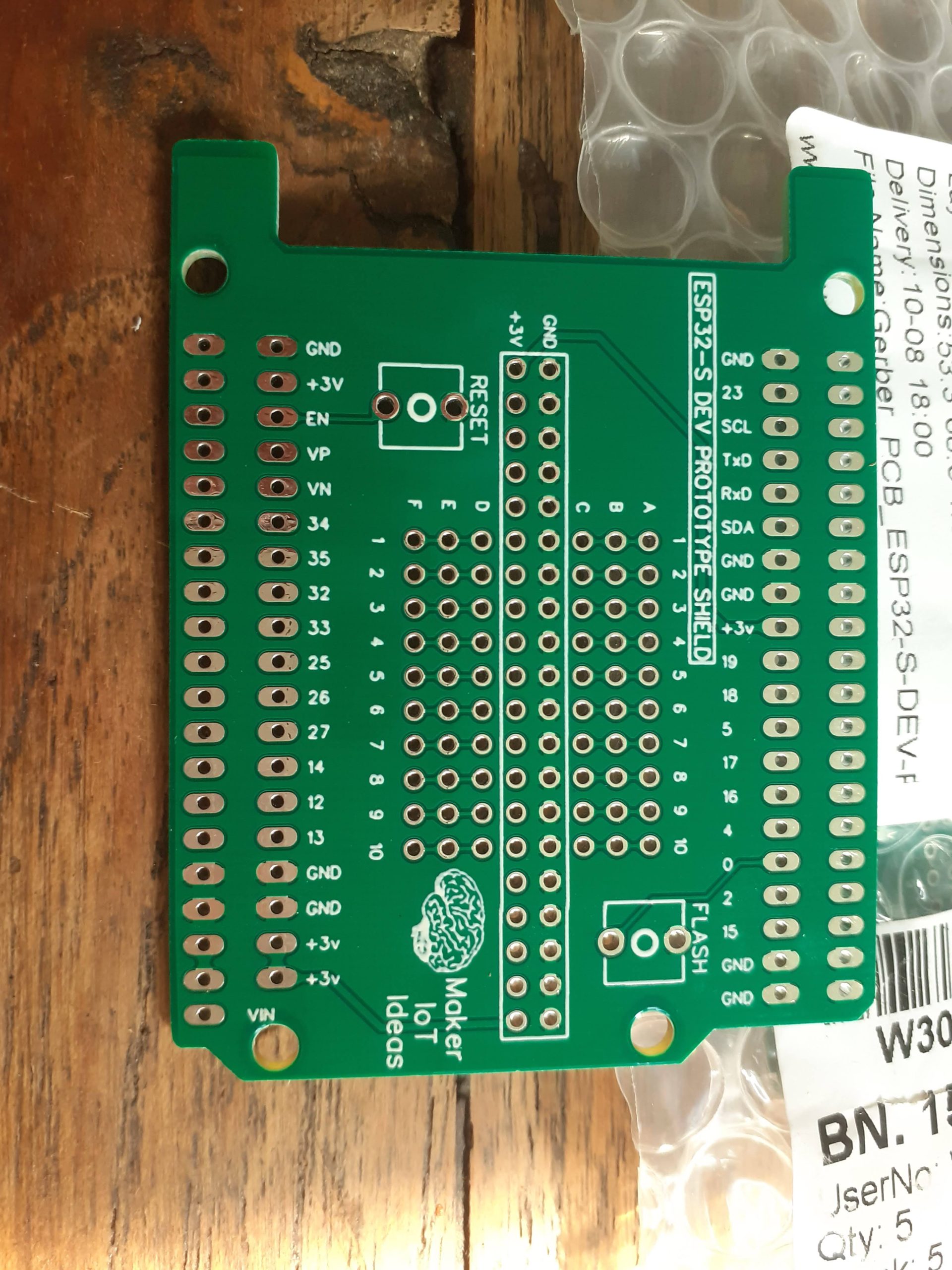 Top view - Not assembled
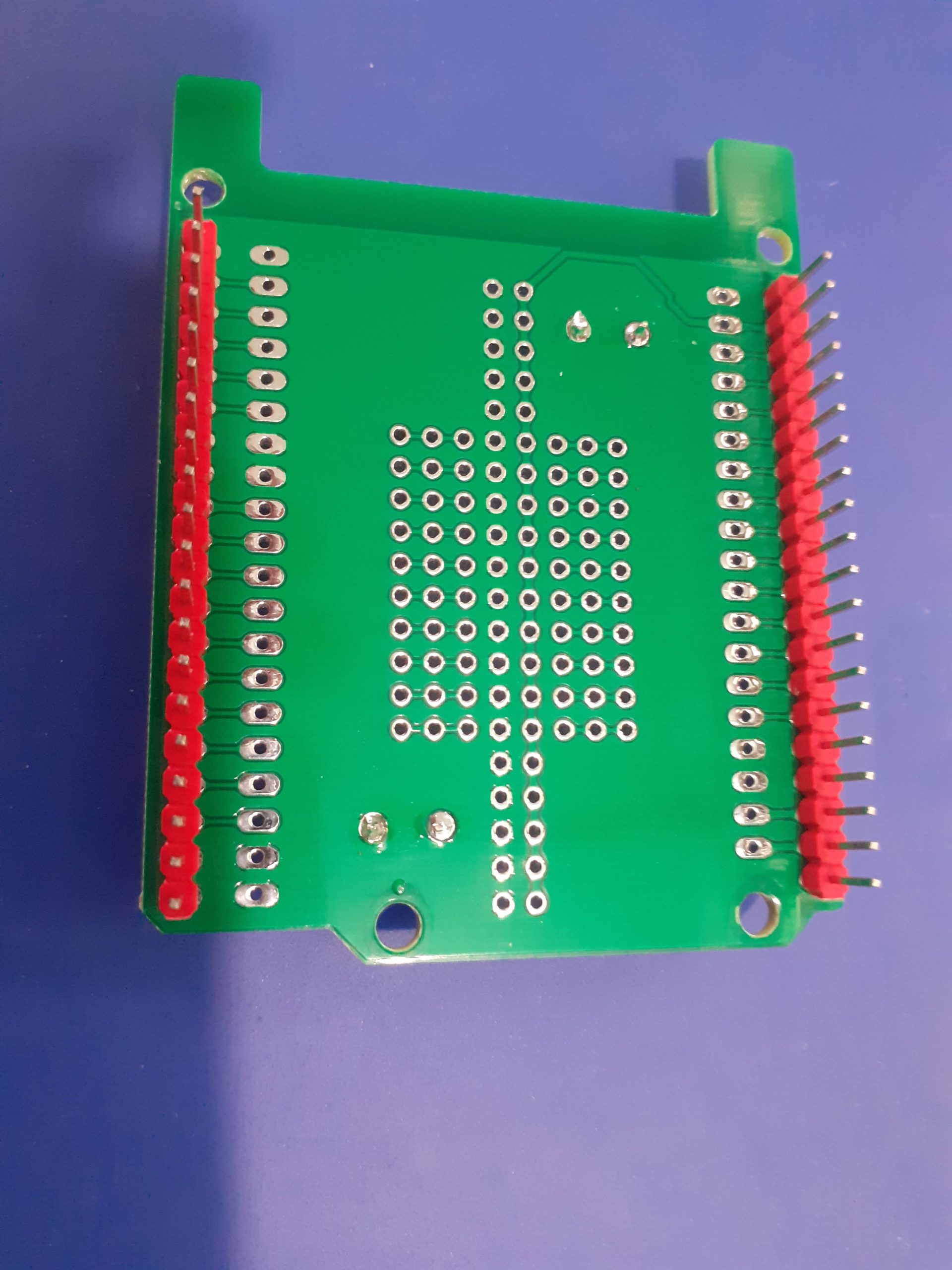 Bottom view - Assembled
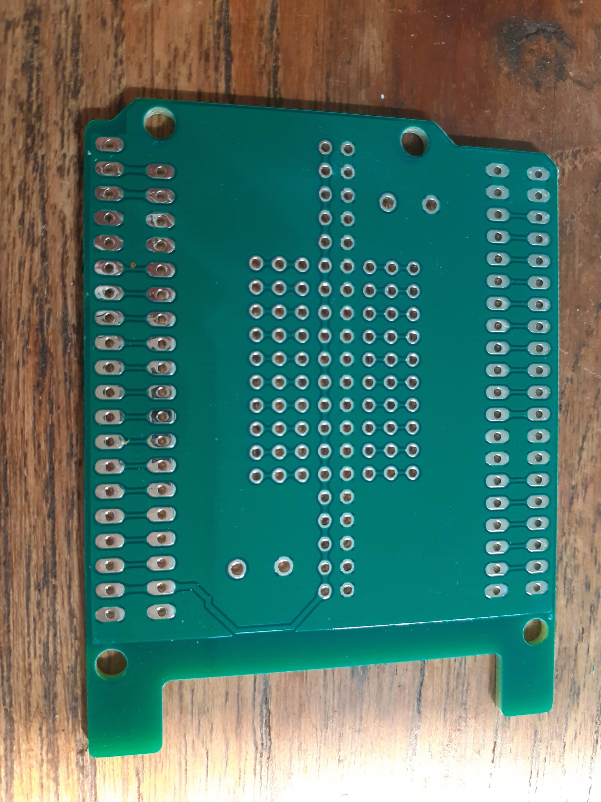 Bottom view - Not assembled
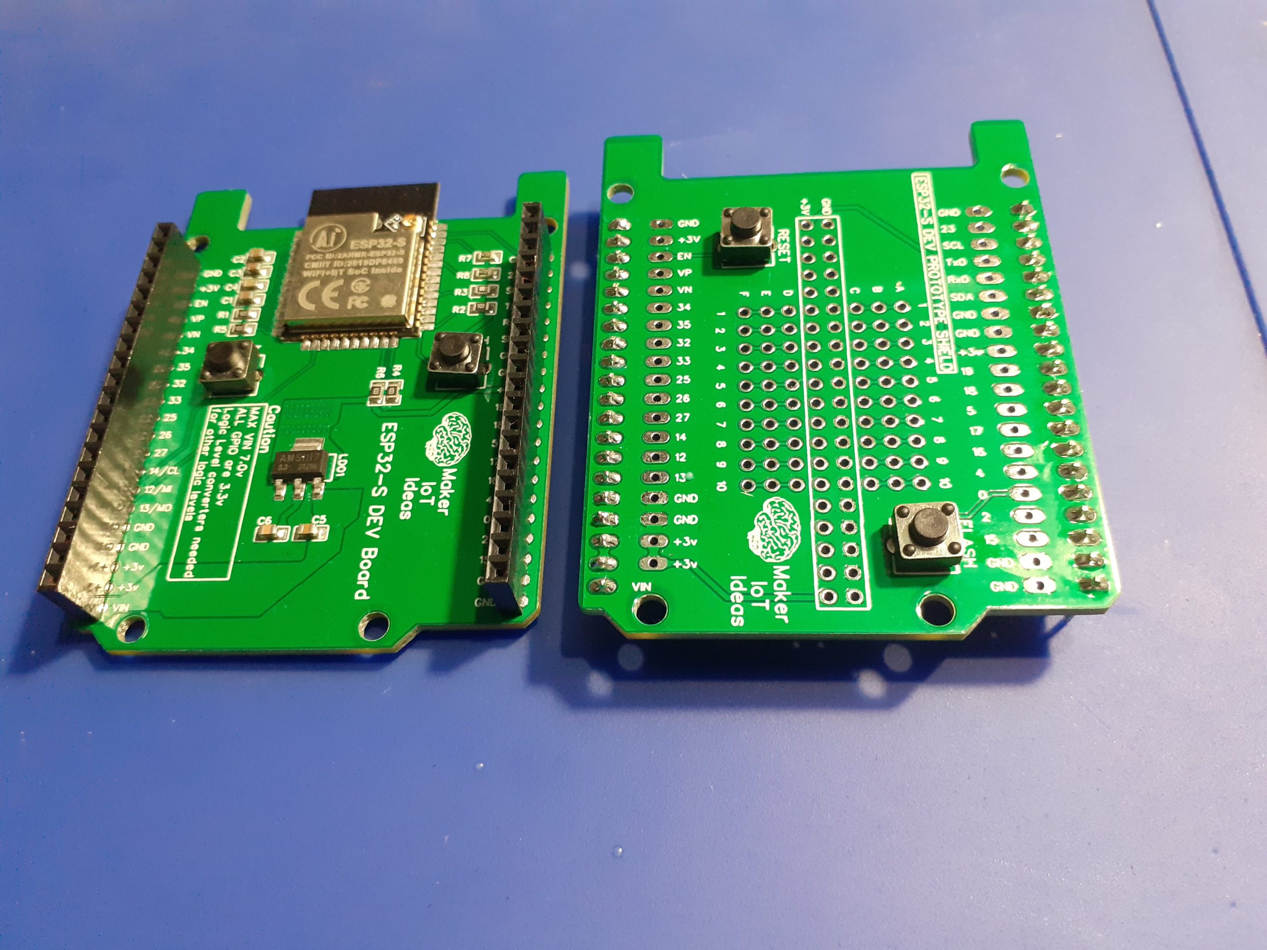 Side-by side
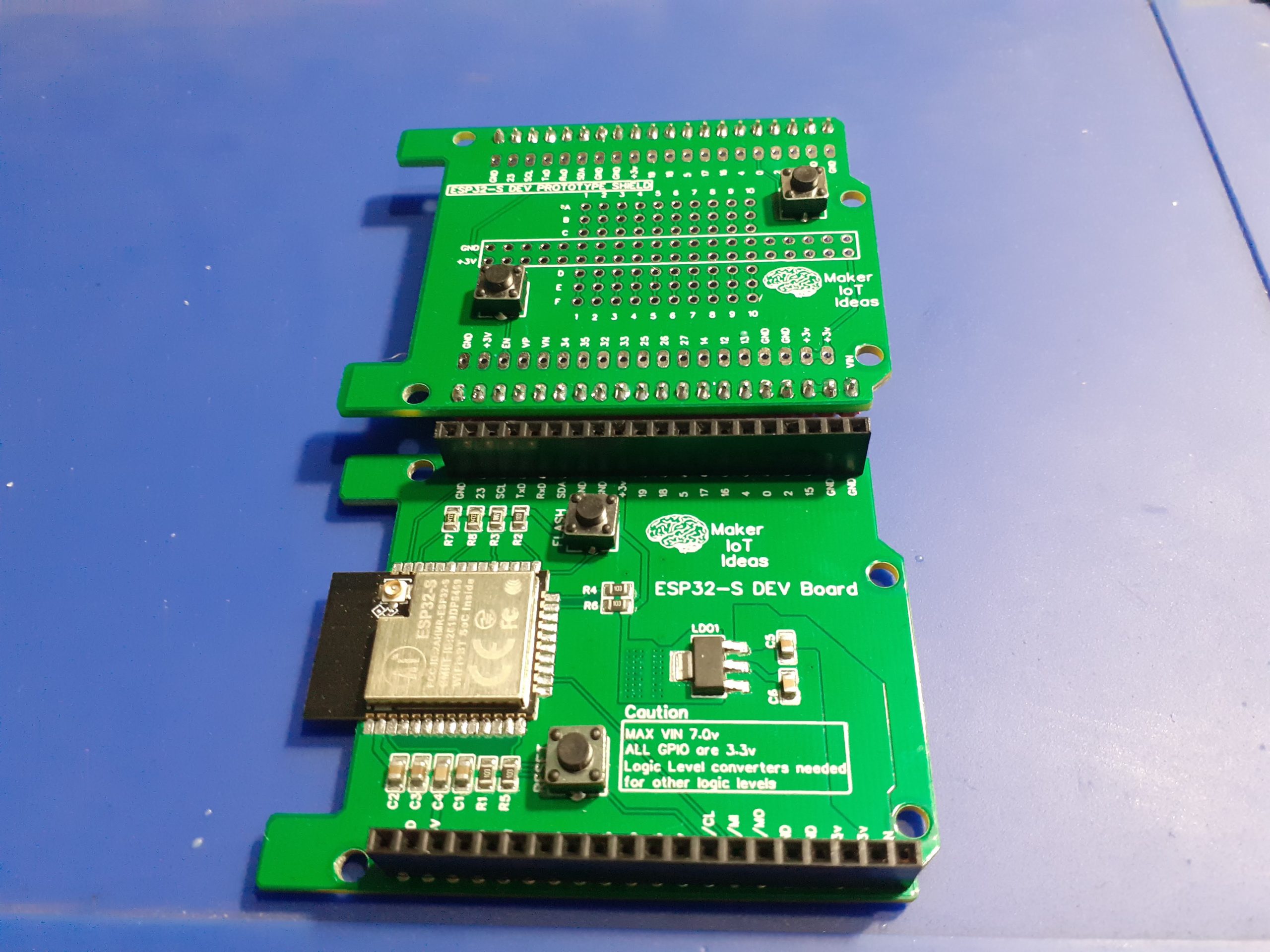 Side by Side
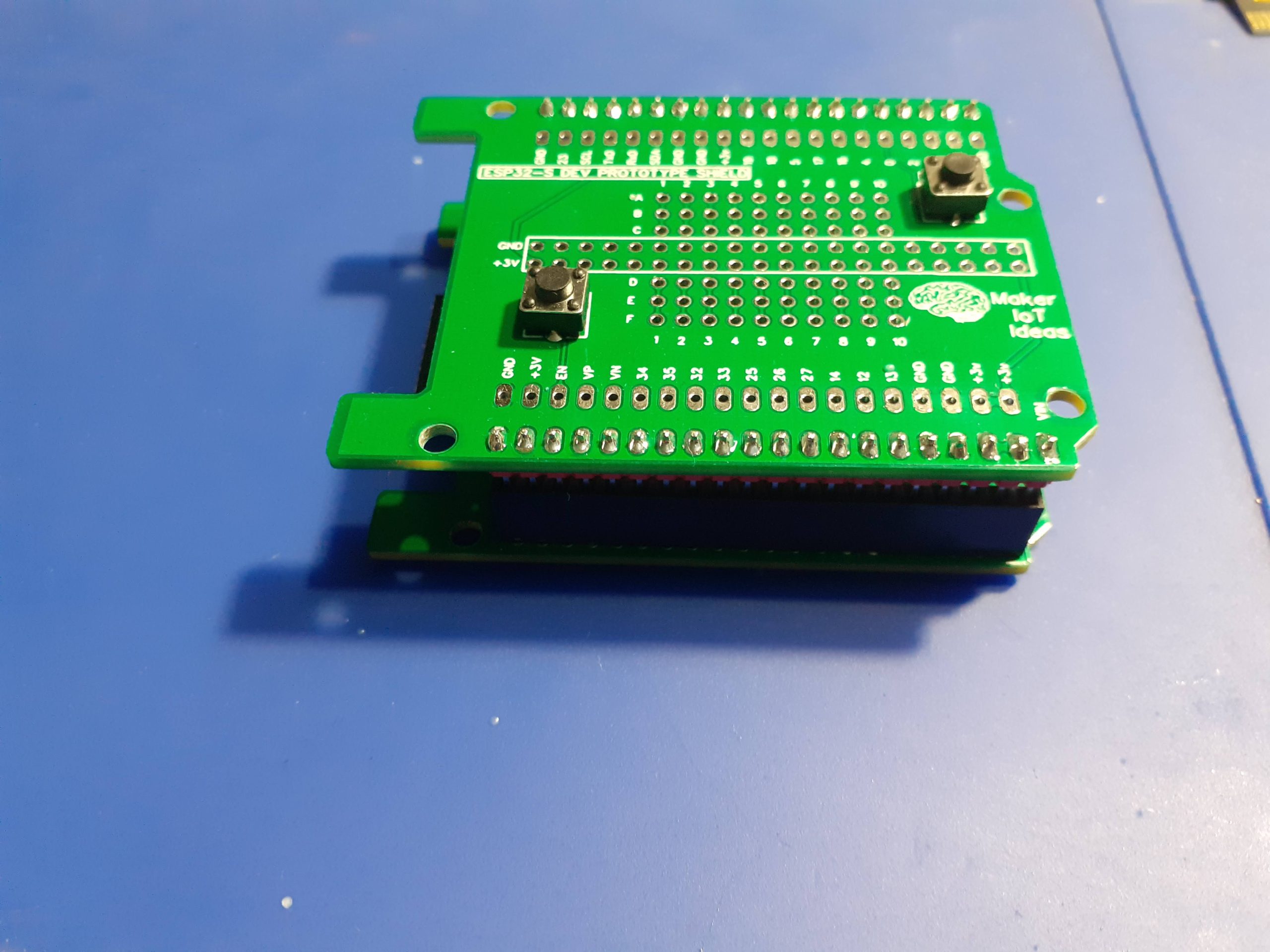 Stacked - Side view
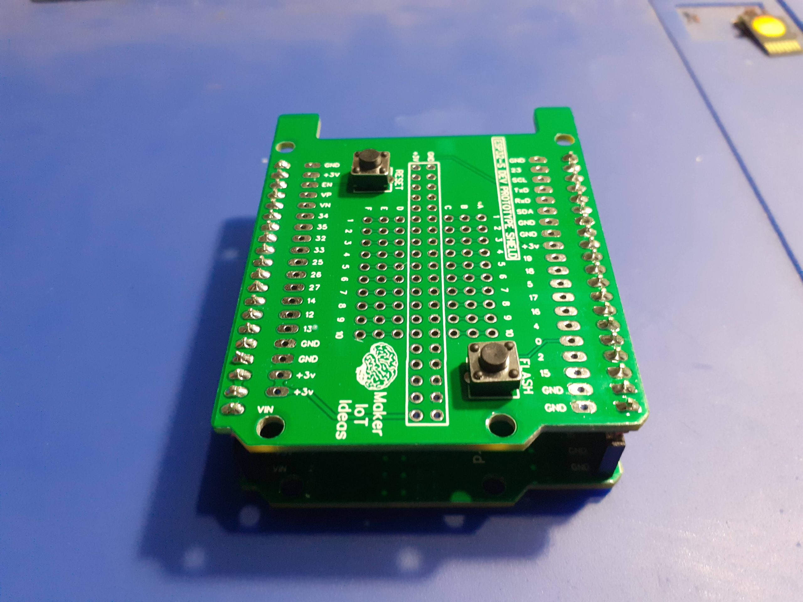 Stacked
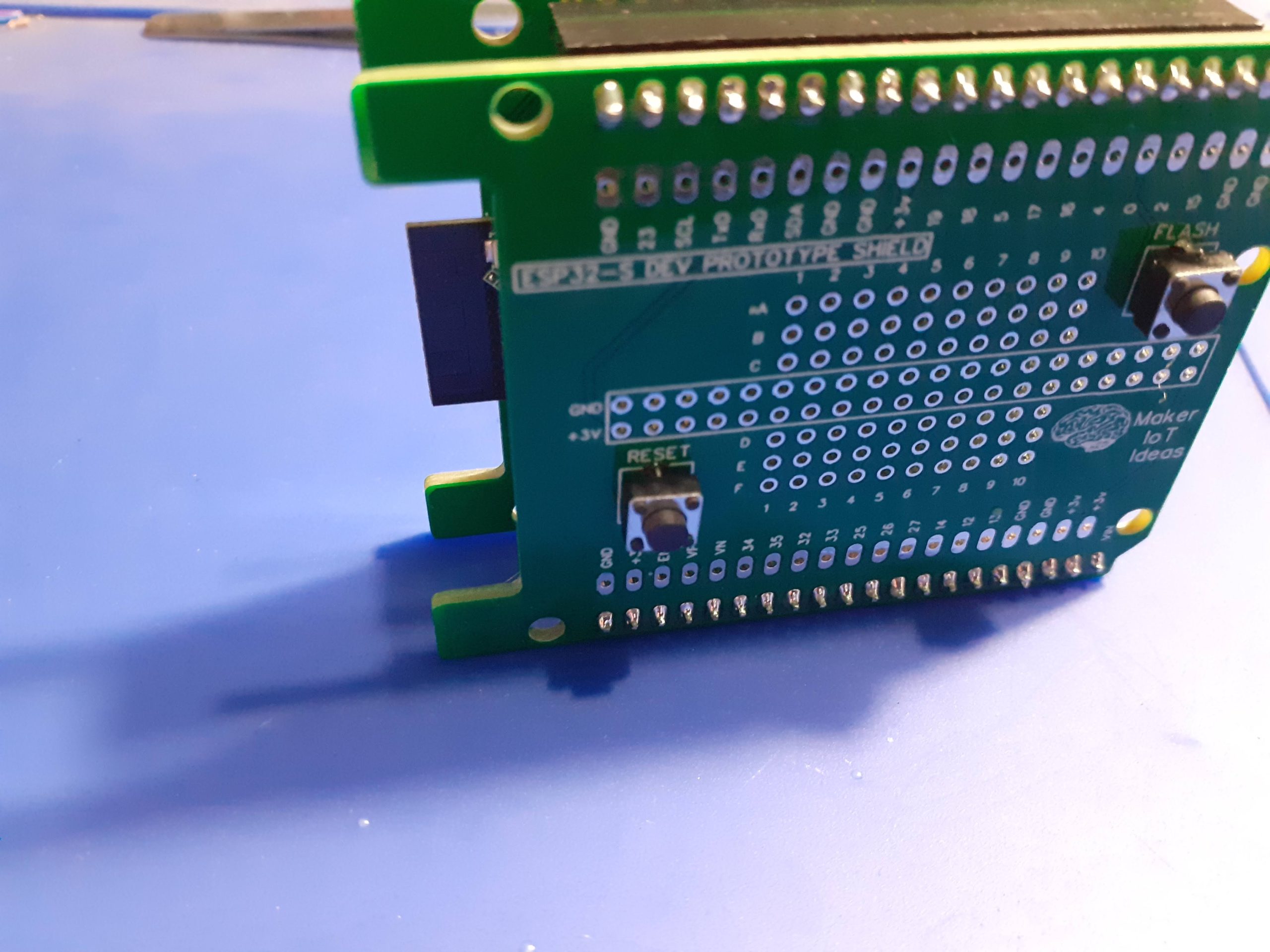 Stacked - top view
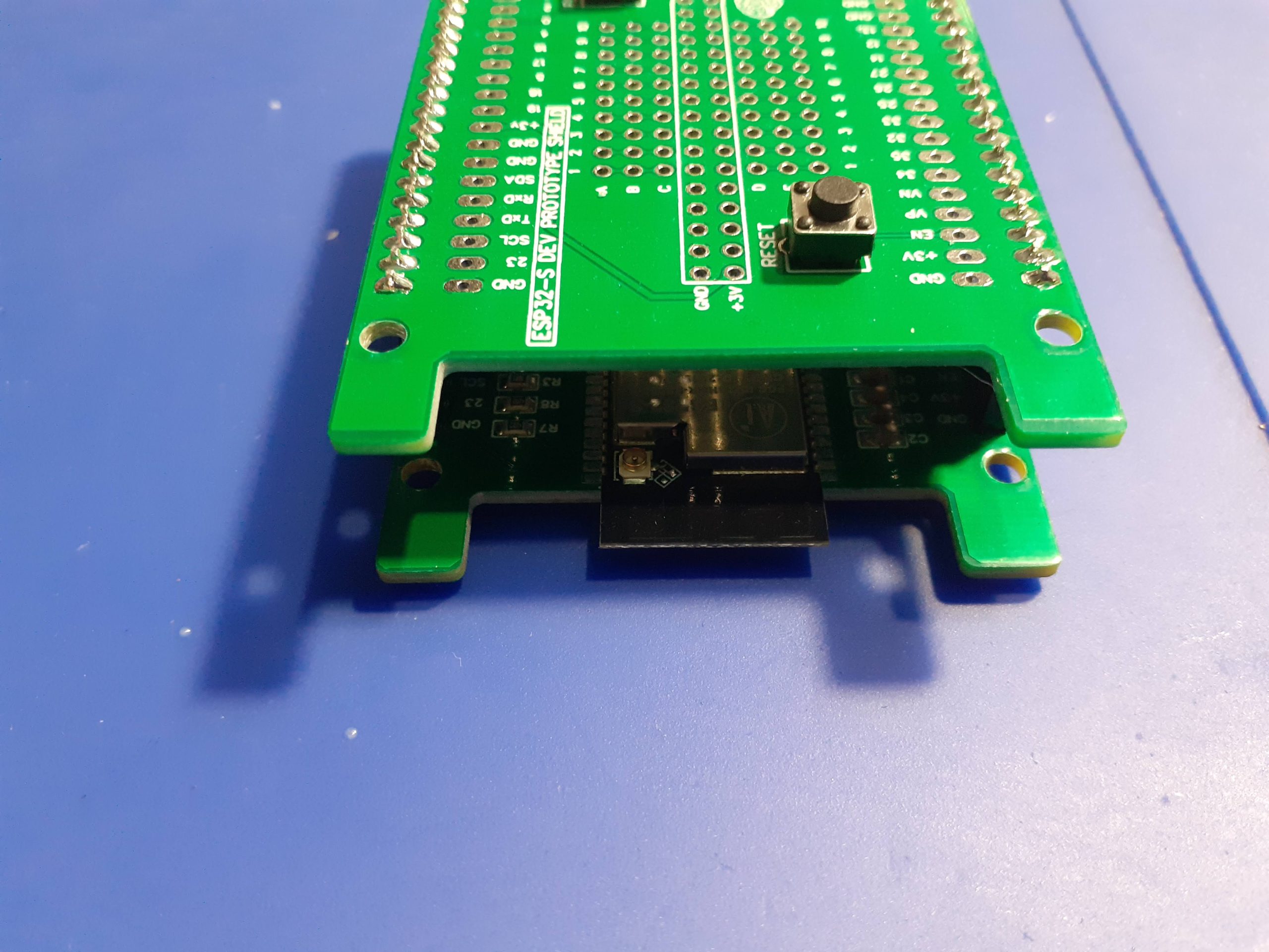 Stacked - from front
Conclusion
Some final thoughts on the completed PCB.
While definitely useful, I have made a purposeful design flaw on this board, by not including a breakout for the VIN pin. My reasoning at that stage was that I would always be powering the device directly from 3.3v, and would therefore not need access to the VIN pin for power.
Upon completion of the device, and while testing it in a stacked configuration, I realised that that VIN pin would have been quite nice to have access to.
Not a big problem though, as if is very easy to add a 2-pin connector to the power rails, or even solder a wire directly to VIN. Ugly, but totally doable, as this is in fact still a prototype, and it can grow and be fine-tuned to my exact requirements over time.
ESP32-S DEV Prototype Shield
*PCBWay community is a sharing platform. We are not responsible for any design issues and parameter issues (board thickness, surface finish, etc.) you choose.
- Comments(0)
- Likes(0)
- 0 USER VOTES
- YOUR VOTE 0.00 0.00
- 1
- 2
- 3
- 4
- 5
- 6
- 7
- 8
- 9
- 10
- 1
- 2
- 3
- 4
- 5
- 6
- 7
- 8
- 9
- 10
- 1
- 2
- 3
- 4
- 5
- 6
- 7
- 8
- 9
- 10
- 1
- 2
- 3
- 4
- 5
- 6
- 7
- 8
- 9
- 10
 More by Jean Redelinghuys MakerIoT2020
-
 PCB_MCP23008_2023-10-08
MCP23008 BreakoutI designed this breakout to assist me during prototyping my next version of the “RP...
-
 PCB_XiaoRP2040-Mouse-REV2
Xiao RP2040 Joystick Mouse – revision 2.00Revision 1.0 of the ProjectOver the last few months, I hav...
-
 Multi Purpose IO Card
Multi-Purpose IO CardWhen we are working on a prototype, we always need access to pushbuttons, encod...
-
 Variable Voltage Power Module
Powering electronics projects are always challenging. This Variable vol...
Variable Voltage Power Module
Variable Voltage Power ModulePowering electronics projects are always challenging. This Variable vol...
-
 I2C Matrix Keypad
An I2C Matrix KeypadThe completed I2C Matrix KeypadIn a previous post this month I introduced my 4×4...
-
 ESP32-S Development Board, in "Arduino Uno" form factor
UPDATE 24/06/2023:This board now has a Hardware Revision 2.0 available. It is the same board but wit...
-
 W307186ASC94_Gerber_PCB_USB-Ports
USB Power Supply ModuleUSB Ports are quite handy to power all our day-to-day electronic devices, but...
-
 Atmega 328P based PWM controller Card
ATMega 328P Based PWM controller CardAs part of my recent ESP-12E I2C Base Board project, I designed...
-
 W307186ASC71_Gerber_PCB_ESP-Now Remote
Today we will look at the remote control unit for the Robotic Toy Car – Part 6.The project is close ...
-
 W307186ASV69_Gerber_PCB_Robot-Car-MCU-Board Prototype
In our last project, we started working on repurposing an old toy car. In this part, Robot Toy Car –...
-
 W307186ASV62_Gerber_PCB_DUAL-H-Bridge
by makeriot2020 on May 27, 2022Many of us have old toys laying around the house, they belong to ou...
-
 CAN-BUS Breakout
Breadboard Compatible CAN-BUS Breakout ModuleWhat is this:Some of us have already used the commonly ...
-
 RA-02 Breakout with Level converters
Breadboard and beginner-friendly RA-02 Breakout ModuleMost Makers and electronics enthusiasts may al...
-
 ATMEGA328P Module with integrated LoRa and CAN Bus
ATMEGA328P Module with integrated LoRa and CAN-BUSINTRODUCTIONIn my quest to perfect my LoRa telemet...
-
 Sx127x-Ra-02-Test-Module with ATMEGA328P-AU
SX127x LoRa/FSK/OOK Prototype Radio BoardI recently had a requirement to do some automation/telemetr...
-
 USB-ASP Programmer ATMEGA8
Build your own USB-ASP Programmer CloneBymakeriot2020 FEB 21, 2022 Arduino, ASP programmerUsing mor...
-
 ATTiny1616-LIGHT-Controller-with-CAN_B_PCB_ATTiny1616-LIGHT-Controller-with-C_2024-09-11
Assembly of the ATTiny1616 Can bus controller PCBThe Assembly of the ATTiny1616 Can Bus Controller P...
-
 ATTiny1616QFN-CAN-Remote-Neopixel-Ligh_PCB_ATTiny1616QFN-CAN-Remote-Neopixel-2024-09-11_2024-09-11
NeoPixel CAN-Bus Module with local controlAs part of my current project to add NeoPixels to the cabi...
-
-
AEL-2011 Power Supply Module
525 0 2 -
AEL-2011 50W Power Amplifier
485 0 2 -
-
-
Custom Mechanical Keyboard
693 0 0 -
Tester for Touch Screen Digitizer without using microcontroller
330 2 2 -
Audio reactive glow LED wristband/bracelet with NFC / RFID-Tags
310 0 1 -
-
-


