|
LCD-20x4BGravitech
|
x 1 | |

|
SMD push buttonPCBWay
|
x 4 | |

|
Arduino UNO R3 development sensor expansion board |
x 1 |

|
Autodesk Fusion 360Autodesk
|
|

|
EagleAutodesk
|
How to create a Human Machine Interface with Arduino
Many machines and devices have one thing in common: a human-machine interface. The human-machine interface can be represented by a screen and a set of buttons.
Its objective is to facilitate the communication and configuration between the man and the machine of the process. Through the HMI, the user can configure the operation of the machine, monitor the data and much more. All through one panel.
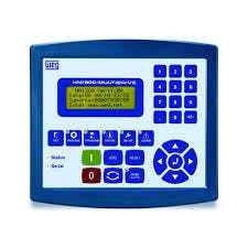
Several machines have an HMI, for example: 3D printer, laser cutting machine and other industrial machines. In the figure below we have an example of HMI.
In this article you will learn to create your own HMI and use it to control loads. This project was developed in partnership with PCBWay and we will release the files for download.
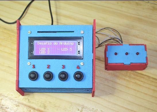
For this project you will learn how to build the HMI in the figure below.
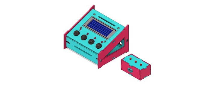
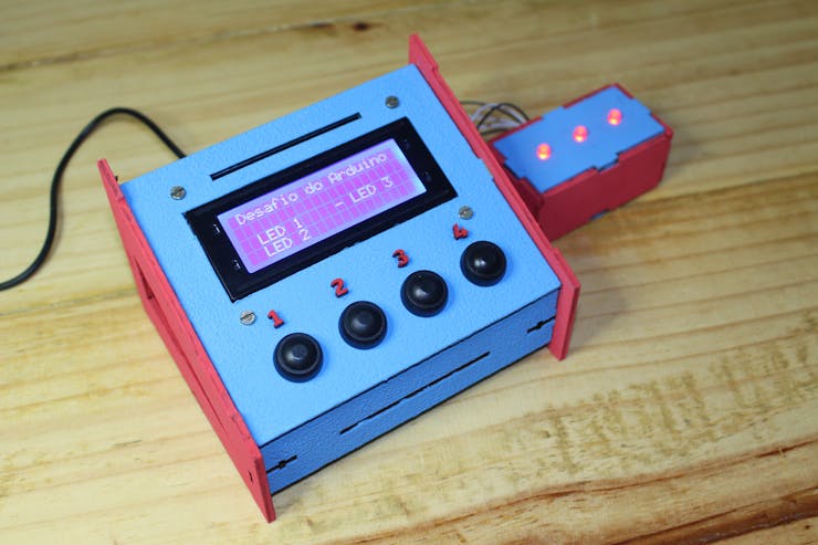
The system consists of 4 general purpose buttons, an LCD and a box with 3 LEDs. The LEDs will be controlled through the HMI system. The structure was manufactured with MDF material through a laser cutting machine.
Below we have some images of the manufactured parts and the final project assembled.
Do you want access to complete documentation of human machine interface files for you to print or laser cut?We will make all the files and the electronic board available for you to earn 10 free PCBWay units.
Follow the step by step below.
- Access the following link and create your account on the PCBWay website.
- Send an email to silicioslab@gmail.com with a screenshot of your created account.
You will receive the email with all files for 3D printing or laser cutting.
Now, we will begin to explain the operation and construction of the Human Machine Interface control logic with Arduino.
Structure and functioning of the Human Machine Interface with Arduino
The structure of the Human Machine Interface with Arduino is formed by a 20x4 LCD screen and 4 buttons. The figure below shows the front structure of the interface.
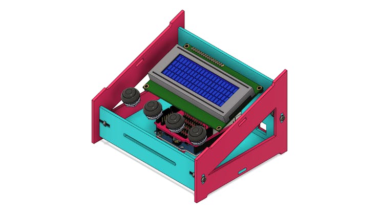
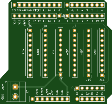
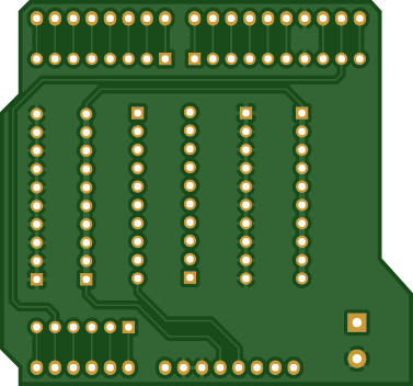
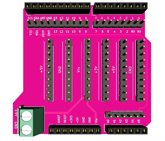
These electronic elements are connected to a pin shield for the Arduino. See the figure below.
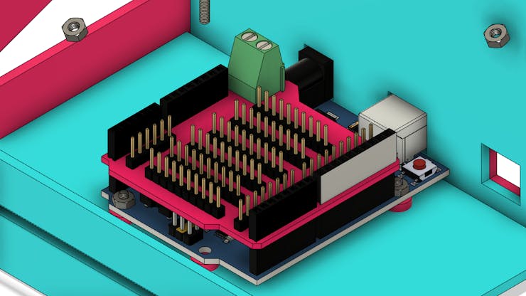
This shield is used to facilitate the connection to Arduino pins and provide the expansion of various Arduino power pins.
Give me a few minutes, and I'll show you big advantages to use this shield.
Why use this Shield?
This shield was created with two purposes:
- Facilitate the connection of electronic elements to the Arduino, because the shield uses male pins.
- Increases the number of +5V, Vin, +3V3 and GND pins. This facilitates the connection of all devices and modules that need power, as the Arduino does not provide enough pins to power the modules in the project.
The board is connected to the female pins of the Arduino and has several male headers for connecting the wires.
Next, we will present the electronic schematic of the connections with the Arduino.
Electronic Scheme of the Project
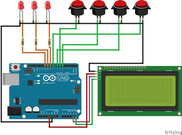
The figure below shows the electronic schematic of the human machine interface project with Arduino.
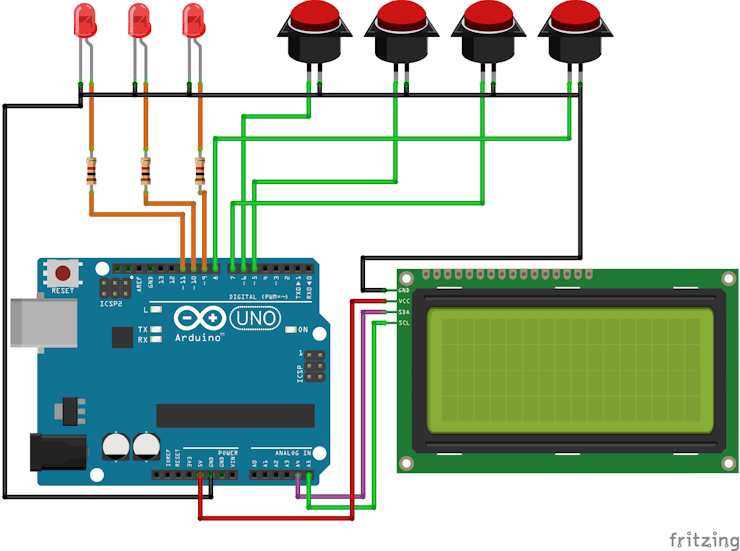
Each button has a purpose in the project. Button 1 is used to move the selector up, button 2 is used to move the selector down, button 3 is used to turn the LED on and off. Finally, we have button 4, which is used to turn off all LEDs.
The information is displayed on the 20x4 LCD through an I2C communication with the Arduino.
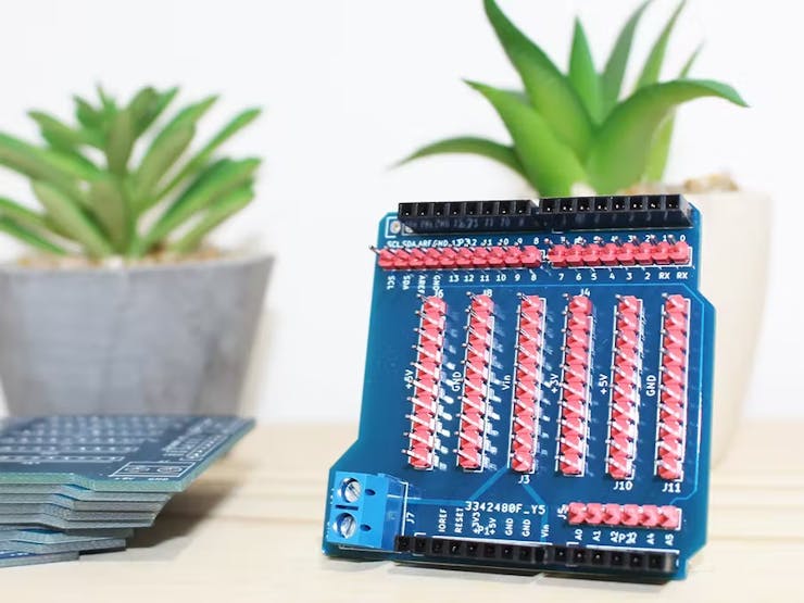
Notice something important. Many electronic components are connected to their GND terminals through wire connections. This generates poor contact and makes the project assembly process difficult. For this reason we developed the connection shield.
As you can see in the Figure, it has several terminals for GND, +3V3, +5V and Vin.
Follow the step by step below and get 10 free PCBWay units.
- Access the following link and create your account on the PCBWay website.
- Download the Gerber files of this PCB.
- Upload the gerber file in PCBWay website.
Next, we will start the full discussion of the code developed in this project.
Programming Logic and Project Operation
The full programming is presented below.
#include <Wire.h> //Biblioteca de Comunicacao I2C
#include <LiquidCrystal_I2C.h> //Biblioteca I2C do LCD 16x2

LiquidCrystal_I2C lcd(0x27,20,4);  // Configurando o endereco do LCD 16x2 para 0x27

#define ButtonUP 6
#define ButtonDown 5
#define ButtonLED 7
#define LEDSOff 8

#define LED3 9
#define LED2 10
#define LED1 11

bool up = 0, down = 0, ControlLED = 0, desligaLEDs;
bool StateUp = 1, StateDown = 1, EnableLCD = 0, StateLEDControl = 1, StateDesliga = 1;
bool StateLED1 = 0, StateLED2 = 0, StateLED3 = 0;

byte count = 1;

//-------------------------------------------
void tela1()
{
  lcd.clear();
  lcd.setCursor(1,0);
  lcd.print("Desafio do Arduino");

  lcd.setCursor(0,2);
  lcd.print("- LED 1      LED 3");
  lcd.setCursor(0,3);
  lcd.print("  LED 2");
}

void tela2()
{
  lcd.clear();
  lcd.setCursor(1,0);
  lcd.print("Desafio do Arduino");

  lcd.setCursor(0,2);
  lcd.print("  LED 1      LED 3");
  lcd.setCursor(0,3);
  lcd.print("- LED 2");
}

void tela3()
{
  lcd.clear();
  lcd.setCursor(1,0);
  lcd.print("Desafio do Arduino");

  lcd.setCursor(0,2);
  lcd.print("  LED 1    - LED 3");
  lcd.setCursor(0,3);
  lcd.print("  LED 2");
}

//-------------------------------------------
void setup()
{
  Serial.begin(9600);

  pinMode(6, INPUT_PULLUP);
  pinMode(5, INPUT_PULLUP);
  pinMode(7, INPUT_PULLUP);
  pinMode(8, INPUT_PULLUP);

  pinMode(9, OUTPUT);
  pinMode(10, OUTPUT);
  pinMode(11, OUTPUT);
  pinMode(13, OUTPUT);

  lcd.init();                      //Inicializacao do LCD
  lcd.backlight();

  lcd.clear();
  tela1();
  lcd.setCursor(1,0);
  lcd.print("Desafio do Arduino");
  lcd.setCursor(0,3);

  delay(2000);
}

void loop()
{
  up = digitalRead(ButtonUP);
  down = digitalRead(ButtonDown);
  ControlLED = digitalRead(ButtonLED);
  desligaLEDs = digitalRead(LEDSOff);

  Serial.println(down);
  delay(50);
  //------------------------------------------------------------------------------

  if(up == 0 && StateUp == 1)
  {
    count++;

    if(count > 3)
    {
      count = 3;
    }

    StateUp = 0;
    EnableLCD = 1;
  }

  if(up == 1 && StateUp == 0)
  {
    StateUp = 1;
  }

  //------------------------------------------------------------------------------
  if(down == 0 && StateDown == 1)
  {
    count--;

    if(count < 1)
    {
      count = 1;
    }

    StateDown = 0;
    EnableLCD = 1;
  }

  if(down == 1 && StateDown == 0)
  {
    StateDown = 1;
  }

  //------------------------------------------------------------------------------
    if(EnableLCD == 1)
    {
        if(count == 1)
        {
          tela1();
        }

        if(count == 2)
        {
          tela2();
        }

        if(count == 3)
        {
           tela3();
        }

        EnableLCD = 0;
    }
  //------------------------------------------------------------------------------
    if(ControlLED == 0 && StateLEDControl == 1)
    {
        Serial.print("Entrou: ");
        Serial.println(count);

        if(count == 1)
        {
          StateLED1 = !StateLED1;
          digitalWrite(LED1, StateLED1);
          Serial.print("Condicao:");
          Serial.println(StateLED1);
        }

        if(count == 2)
        {
          StateLED2 = !StateLED2;
          digitalWrite(LED2, StateLED2);
          Serial.println(StateLED2);
        }

        if(count == 3)
        {
          StateLED3 = !StateLED3;
          digitalWrite(LED3, StateLED3);
          Serial.println(StateLED3);
        }

        StateLEDControl = 0;
    }

    if(ControlLED == 1 && StateLEDControl == 0)
    {
        StateLEDControl = 1;
    }

    if(desligaLEDs == 0 && StateDesliga == 1)
    {
        StateLED1 = 0;
        StateLED2 = 0;
        StateLED3 = 0;

        digitalWrite(LED1, StateLED1);
        digitalWrite(LED2, StateLED2);
        digitalWrite(LED3, StateLED3);

        StateDesliga = 0;
    }

    if(desligaLEDs == 1 && StateDesliga == 0)
    {
        StateDesliga  = 1;
    }
}
The developed logic is very simple. Initially, the declaration of libraries, definition of names for each number of digital pins and declaration of variables used in the project were carried out.
#include <Wire.h> //Biblioteca de Comunicacao I2C
#include <LiquidCrystal_I2C.h> //Biblioteca I2C do LCD 16x2

LiquidCrystal_I2C lcd(0x27,20,4);  // Configurando o endereco do LCD 16x2 para 0x27

#define ButtonUP 6
#define ButtonDown 5
#define ButtonLED 7
#define LEDSOff 8

#define LED3 9
#define LED2 10
#define LED1 11

bool up = 0, down = 0, ControlLED = 0, desligaLEDs;
bool StateUp = 1, StateDown = 1, EnableLCD = 0, StateLEDControl = 1, StateDesliga = 1;
bool StateLED1 = 0, StateLED2 = 0, StateLED3 = 0;

byte count = 1;
After that, 3 functions were declared. The functions presented below will be used to present each screen of the project on the 20x4 LCD.
void tela1()
{
  lcd.clear();
  lcd.setCursor(1,0);
  lcd.print("Desafio do Arduino");

  lcd.setCursor(0,2);
  lcd.print("- LED 1      LED 3");
  lcd.setCursor(0,3);
  lcd.print("  LED 2");
}

void tela2()
{
  lcd.clear();
  lcd.setCursor(1,0);
  lcd.print("Desafio do Arduino");

  lcd.setCursor(0,2);
  lcd.print("  LED 1      LED 3");
  lcd.setCursor(0,3);
  lcd.print("- LED 2");
}

void tela3()
{
  lcd.clear();
  lcd.setCursor(1,0);
  lcd.print("Desafio do Arduino");

  lcd.setCursor(0,2);
  lcd.print("  LED 1    - LED 3");
  lcd.setCursor(0,3);
  lcd.print("  LED 2");
}
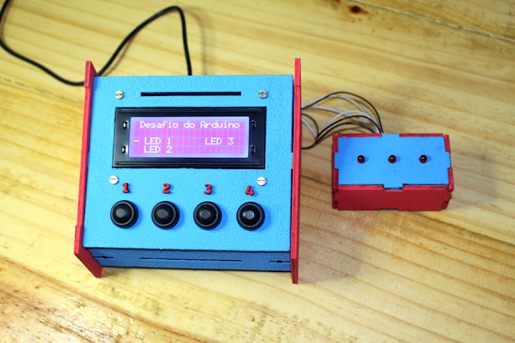
The first function (tela1) is used to display the home screen. This screen presents the selection cursor on the LED 1 option. See the figure below.
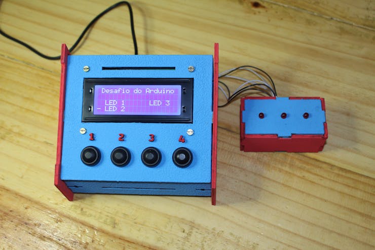
The tela2 function is used to display the screen with the selection cursor on the LED 2 option. The figure below shows screen 2.
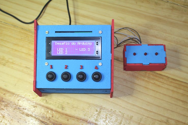
Finally, we have the tela3 function. It is used to display the cursor on the LED 3 option. See the figure below.
After declaring the functions, we have the void setup function.
void setup()
{
  Serial.begin(9600);

  pinMode(6, INPUT_PULLUP);
  pinMode(5, INPUT_PULLUP);
  pinMode(7, INPUT_PULLUP);
  pinMode(8, INPUT_PULLUP);

  pinMode(9, OUTPUT);
  pinMode(10, OUTPUT);
  pinMode(11, OUTPUT);
  pinMode(13, OUTPUT);

  lcd.init();                      //Inicializacao do LCD
  lcd.backlight();

  lcd.clear();
  tela1();
  lcd.setCursor(1,0);
  lcd.print("Desafio do Arduino");
  lcd.setCursor(0,3);

  delay(2000);
}
It is used to configure the digital pins, initialize the LCD and display screen 1, which is the initial screen of the project.
Next, we have the void loop function, where we have the main logic of the project.
The void loop function
In the initial lines of code we read the 4 buttons and wait a time of 50 ms to handle the debounce. After that, the system will check if any of the buttons are pressed.
void loop()
{
  up = digitalRead(ButtonUP);
  down = digitalRead(ButtonDown);
  ControlLED = digitalRead(ButtonLED);
  desligaLEDs = digitalRead(LEDSOff);

  Serial.println(down);
  delay(50);
  //------------------------------------------------------------------------------

  if(up == 0 && StateUp == 1)
  {
    count++;

    if(count > 3)
    {
      count = 3;
    }

    StateUp = 0;
    EnableLCD = 1;
  }

  if(up == 1 && StateUp == 0)
  {
    StateUp = 1;
  }

  //------------------------------------------------------------------------------
  if(down == 0 && StateDown == 1)
  {
    count--;

    if(count < 1)
    {
      count = 1;
    }

    StateDown = 0;
    EnableLCD = 1;
  }

  if(down == 1 && StateDown == 0)
  {
    StateDown = 1;
  }

  //------------------------------------------------------------------------------
    if(EnableLCD == 1)
    {
        if(count == 1)
        {
          tela1();
        }

        if(count == 2)
        {
          tela2();
        }

        if(count == 3)
        {
           tela3();
        }

        EnableLCD = 0;
    }
  //------------------------------------------------------------------------------
    if(ControlLED == 0 && StateLEDControl == 1)
    {
        Serial.print("Entrou: ");
        Serial.println(count);

        if(count == 1)
        {
          StateLED1 = !StateLED1;
          digitalWrite(LED1, StateLED1);
          Serial.print("Condicao:");
          Serial.println(StateLED1);
        }

        if(count == 2)
        {
          StateLED2 = !StateLED2;
          digitalWrite(LED2, StateLED2);
          Serial.println(StateLED2);
        }

        if(count == 3)
        {
          StateLED3 = !StateLED3;
          digitalWrite(LED3, StateLED3);
          Serial.println(StateLED3);
        }

        StateLEDControl = 0;
    }

    if(ControlLED == 1 && StateLEDControl == 0)
    {
        StateLEDControl = 1;
    }

    if(desligaLEDs == 0 && StateDesliga == 1)
    {
        StateLED1 = 0;
        StateLED2 = 0;
        StateLED3 = 0;

        digitalWrite(LED1, StateLED1);
        digitalWrite(LED2, StateLED2);
        digitalWrite(LED3, StateLED3);

        StateDesliga = 0;
    }

    if(desligaLEDs == 1 && StateDesliga == 0)
    {
        StateDesliga  = 1;
    }
}
See the code portion to verify that the move up button is pressed.
if(up == 0 && StateUp == 1)
  {
    count++;

    if(count > 3)
    {
      count = 3;
    }

    StateUp = 0;
    EnableLCD = 1;
  }

  if(up == 1 && StateUp == 0)
  {
    StateUp = 1;
  }
The system checks that the variable up is 0 and that the variable StateUp is equal to 1. What does this condition mean? If the up variable is 0, then it means that the button is currently pressed.
The system checks that the variable up is 0 and that the variable StateUp is equal to 1. What does this condition mean? If the up variable is 0, then it means that the button is currently pressed.
If the StateUp variable is equal to 1, then it means that previously our button was released.
So, if this condition is true, the code flow will enter the condition and execute the code block. The first command executed is to increment the count variable.
count++;
What is it for and why should we increment the count variable?
This variable is the big secret for you to show any human machine interface configuration screen. For each value of the count variable, our system will present a specific screen.
- count is equal to 1? If yes, then screen 1 should be displayed.
- count is equal to 2? If yes, then screen 2 should be displayed.
- count is equal to 3? If yes, then screen 3 should be displayed.
After incrementing the variable, the system checks if the value of count is greater than 3. If yes, then the system assigns 3 to the variable and prevents it from displaying the value 4. This serves to limit its value, as we only have 3 screens to be presented.
if(count > 3)
{
    count = 3;
}
At the end of the condition, a value of 0 is assigned to the StateUp variable and a value of 1 to the EnableLCD variable.
StateUp = 0;
EnableLCD = 1;
The value 0 is assigned to the StateUp variable to update its state. This means that the current state of the button is triggered.
That way, the code flow will not enter the condition in the next loop.
This prevents the count variable from incrementing multiple times when the button is pressed.
if(up == 0 && StateUp == 1)
The EnableLCD variable receives a value of 1 to enable the display of information on the LCD screen.
Now we have the other condition associated with the move up button.
if(up == 1 && StateUp == 0)
{
  StateUp = 1;
}
This condition is used to check if the user has released the button. When the user releases the button, the up variable receives value 1 and the StateUp variable, which stores its previous state, has the value 0 (button pressed).
In this case, the system assigns a value of 1 to the StateUp variable. This lets you update the button's new previous state to off.
The next condition is similar to the move down button condition. See below.
if(down == 0 && StateDown == 1)
{
    count--;

    if(count < 1)
    {
      count = 1;
    }

    StateDown = 0;
    EnableLCD = 1;
}

if(down == 1 && StateDown == 0)
{
    StateDown = 1;
}
The only difference between them is in the mathematical operation with the count variable.
In this condition the count variable is decremented.
Next we have the condition to check if the LCD is enabled to show a value on its screen.
if(EnableLCD == 1)
    {
        if(count == 1)
        {
          tela1();
        }

        if(count == 2)
        {
          tela2();
        }

        if(count == 3)
        {
           tela3();
        }

        EnableLCD = 0;
    }
Remember, every time one of the move up or down buttons is pressed, the LCD will be enabled to show the information on your screen.
EnableLCD = 1;
Inside the condition, the system will check what is the value of the count variable. For each value there is a screen that can be displayed. As mentioned earlier, we have:
- count is equal to 1? If yes, then screen 1 should be displayed.
- count is equal to 2? If yes, then screen 2 should be displayed.
- count is equal to 3? If yes, then screen 3 should be displayed.
At the end of the condition, the system assigns the value 0 to the EnableLCD variable.
This feature is used to prevent the system from always continuously updating the information on the screen and causing unwanted effects to users.
Next, we will present the structure for activating the LEDs through button 3.
if(ControlLED == 0 && StateLEDControl == 1)
{

        if(count == 1)
        {
          StateLED1 = !StateLED1;
          digitalWrite(LED1, StateLED1);
        }

        if(count == 2)
        {
          StateLED2 = !StateLED2;
          digitalWrite(LED2, StateLED2);
        }

        if(count == 3)
        {
          StateLED3 = !StateLED3;
          digitalWrite(LED3, StateLED3);
        }

        StateLEDControl = 0;
    }

    if(ControlLED == 1 && StateLEDControl == 0)
    {
        StateLEDControl = 1;
}
Note that the structure is similar to the structure of conditions for buttons 1 and 2. However, the command block is different. See below.
if(count == 1)
{
     StateLED1 = !StateLED1;
     digitalWrite(LED1, StateLED1);
}

if(count == 2)
{
     StateLED2 = !StateLED2;
     digitalWrite(LED2, StateLED2);
}

if(count == 3)
{
     StateLED3 = !StateLED3;
     digitalWrite(LED3, StateLED3);
}
The LED control button is used to turn each LED on and off. When the button is pressed, the system checks the value of the count variable.
If count is equal to 1, then the system inverts the value of the variable that stores the LED state.
StateLED1 = !StateLED1;
It then triggers the LED pin with the value of the LED state variable.
digitalWrite(LED1, StateLED1);
This process is performed for each of the LEDs. Turning on or off is based on the value of the count variable.
Below we have images of each LED being controlled.
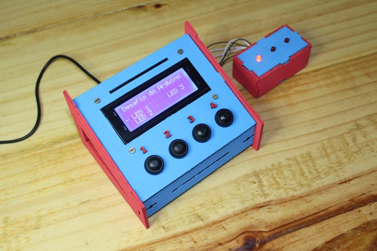
Finally, we have the possibility to turn off all the LEDs through button 4.
if(desligaLEDs == 0 && StateDesliga == 1)
{
    StateLED1 = 0;
    StateLED2 = 0;
    StateLED3 = 0;

    digitalWrite(LED1, StateLED1);
    digitalWrite(LED2, StateLED2);
    digitalWrite(LED3, StateLED3);

    StateDesliga = 0;
}

if(desligaLEDs == 1 && StateDesliga == 0)
{
    StateDesliga  = 1;
}
When the button is pressed, the system updates all the state variables of the 3 LEDs to 0 and updates the state of the pins of each LED.
Below we have the images of all the LEDs being turned off after pressing button 4.
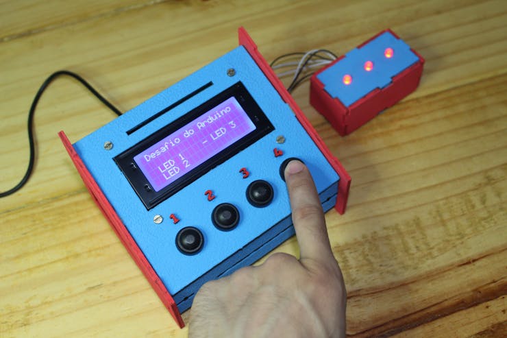
Finally you understood the complete operation of the human machine interface control system with Arduino. Through this project you were able to control 3 LED's.
However, the human machine interface structure can be used to apply it to any project or idea you want to develop.
Do you have any questions about how the project works? Write your questions in the comments and I will help you.
Download of the project files
To access the 3D files of the case, you must follow the steps below:
- Access the following link and create your account on the PCBWay website.
- Send an email to silicioslab@gmail.com with a screenshot of your created account.
- You will receive the email with all files for 3D printing or laser cutting.
Do you want to win 10 units of this circuit board to facilitate the assembly of your projects?

Follow the step by step below and get 10 free PCBWay units.
- Access the following link and create your account on the PCBWay website.
- Download the Gerber files of this PCB.
- Upload the gerber file in PCBWay website.
Acknowledgment
Thanks to the PCBWay for support and produce and assembly PCBs with better quality.
#include <Wire.h> //Biblioteca de Comunicacao I2C #include <LiquidCrystal_I2C.h> //Biblioteca I2C do LCD 16x2 LiquidCrystal_I2C lcd(0x27,20,4); // Configurando o endereco do LCD 16x2 para 0x27 #define ButtonUP 6 #define ButtonDown 5 #define ButtonLED 7 #define LEDSOff 8 #define LED3 9 #define LED2 10 #define LED1 11 bool up = 0, down = 0, ControlLED = 0, desligaLEDs; bool StateUp = 1, StateDown = 1, EnableLCD = 0, StateLEDControl = 1, StateDesliga = 1; bool StateLED1 = 0, StateLED2 = 0, StateLED3 = 0; byte count = 1; //------------------------------------------- void tela1() { lcd.clear(); lcd.setCursor(1,0); lcd.print("Desafio do Arduino"); lcd.setCursor(0,2); lcd.print("- LED 1 LED 3"); lcd.setCursor(0,3); lcd.print(" LED 2"); } void tela2() { lcd.clear(); lcd.setCursor(1,0); lcd.print("Desafio do Arduino"); lcd.setCursor(0,2); lcd.print(" LED 1 LED 3"); lcd.setCursor(0,3); lcd.print("- LED 2"); } void tela3() { lcd.clear(); lcd.setCursor(1,0); lcd.print("Desafio do Arduino"); lcd.setCursor(0,2); lcd.print(" LED 1 - LED 3"); lcd.setCursor(0,3); lcd.print(" LED 2"); } //------------------------------------------- void setup() { Serial.begin(9600); pinMode(6, INPUT_PULLUP); pinMode(5, INPUT_PULLUP); pinMode(7, INPUT_PULLUP); pinMode(8, INPUT_PULLUP); pinMode(9, OUTPUT); pinMode(10, OUTPUT); pinMode(11, OUTPUT); pinMode(13, OUTPUT); lcd.init(); //Inicializacao do LCD lcd.backlight(); lcd.clear(); tela1(); lcd.setCursor(1,0); lcd.print("Desafio do Arduino"); lcd.setCursor(0,3); delay(2000); } void loop() { up = digitalRead(ButtonUP); down = digitalRead(ButtonDown); ControlLED = digitalRead(ButtonLED); desligaLEDs = digitalRead(LEDSOff); Serial.println(down); delay(50); //------------------------------------------------------------------------------ if(up == 0 && StateUp == 1) { count++; if(count > 3) { count = 3; } StateUp = 0; EnableLCD = 1; } if(up == 1 && StateUp == 0) { StateUp = 1; } //------------------------------------------------------------------------------ if(down == 0 && StateDown == 1) { count--; if(count < 1) { count = 1; } StateDown = 0; EnableLCD = 1; } if(down == 1 && StateDown == 0) { StateDown = 1; } //------------------------------------------------------------------------------ if(EnableLCD == 1) { if(count == 1) { tela1(); } if(count == 2) { tela2(); } if(count == 3) { tela3(); } EnableLCD = 0; } //------------------------------------------------------------------------------ if(ControlLED == 0 && StateLEDControl == 1) { Serial.print("Entrou: "); Serial.println(count); if(count == 1) { StateLED1 = !StateLED1; digitalWrite(LED1, StateLED1); Serial.print("Condicao:"); Serial.println(StateLED1); } if(count == 2) { StateLED2 = !StateLED2; digitalWrite(LED2, StateLED2); Serial.println(StateLED2); } if(count == 3) { StateLED3 = !StateLED3; digitalWrite(LED3, StateLED3); Serial.println(StateLED3); } StateLEDControl = 0; } if(ControlLED == 1 && StateLEDControl == 0) { StateLEDControl = 1; } if(desligaLEDs == 0 && StateDesliga == 1) { StateLED1 = 0; StateLED2 = 0; StateLED3 = 0; digitalWrite(LED1, StateLED1); digitalWrite(LED2, StateLED2); digitalWrite(LED3, StateLED3); StateDesliga = 0; } if(desligaLEDs == 1 && StateDesliga == 0) { StateDesliga = 1; } }
How to create a Human Machine Interface with Arduino
*PCBWay community is a sharing platform. We are not responsible for any design issues and parameter issues (board thickness, surface finish, etc.) you choose.

Raspberry Pi 5 7 Inch Touch Screen IPS 1024x600 HD LCD HDMI-compatible Display for RPI 4B 3B+ OPI 5 AIDA64 PC Secondary Screen(Without Speaker)
BUY NOW
ESP32-S3 4.3inch Capacitive Touch Display Development Board, 800×480, 5-point Touch, 32-bit LX7 Dual-core Processor
BUY NOW
Raspberry Pi 5 7 Inch Touch Screen IPS 1024x600 HD LCD HDMI-compatible Display for RPI 4B 3B+ OPI 5 AIDA64 PC Secondary Screen(Without Speaker)
BUY NOW- Comments(0)
- Likes(2)
 Log in to post comments.
-
 Boris
Sep 09,2022
-
 Silícios Lab silicioslab
Mar 23,2022
- 0 USER VOTES
- YOUR VOTE 0.00 0.00
- 1
- 2
- 3
- 4
- 5
- 6
- 7
- 8
- 9
- 10
- 1
- 2
- 3
- 4
- 5
- 6
- 7
- 8
- 9
- 10
- 1
- 2
- 3
- 4
- 5
- 6
- 7
- 8
- 9
- 10
- 1
- 2
- 3
- 4
- 5
- 6
- 7
- 8
- 9
- 10
 More by Silícios Lab silicioslab
-
 Electronic Enclosure for Programmable Logic Controller
The housing developed for programmable logic controllers is a practical and efficient solution for t...
-
 Payment PCB for machines and services
IntroductionIn many commercial establishments, hospitals and other places, there are video game equi...
-
 Relay High Power Printed Circuit Board
IntroductionEfficient management of electrical loads is essential for optimizing performance and saf...
-
 Weather gadget with clock through ESP8266
IntroductionImagine a device that combines technology with an elegant design, bringing functionality...
-
 ESP32 MPU6050 Monitor
IntroductionVarious industrial equipment is essential for the adequate production of products, parts...
-
 Digital Speedometer for Bicycles
IntroductionCycling, increasingly popular both as a recreational activity and as a means of transpor...
-
 How to measure weight with Load Cell and HX711
IntroductionThe purpose of this project is to develop a printed circuit board (PCB) that allows weig...
-
 Electronic Enclosure applied for electronic projects
IntroductionWhen designing electronics, the enclosure plays a crucial role that is often overlooked....
-
 IoT Indoor system with ESP32 to monitor Temperature, Humidity, Pressure, and Air Quality
IntroductionAir quality, temperature, humidity and pressure are essential elements to ensure healthy...
-
 WS2812B RGB LED Controller with ESP8266 via WiFi
IntroductionWS2812b addressable RGB LEDs are devices widely used in lighting projects. They are foun...
-
 Electronic Board for Cutting Electrical Power to Devices and Machines
IntroductionAn energy saving system for cutting electrical energy in machines is a fundamental piece...
-
 PCB Board Home Automation with ESP8266
IntroductionThe incorporation of the ESP8266 module into home automation represents a significant ad...
-
 Dedicated Control Board for Mobile Robots with Wheels
IntroductionFor a long time we developed several prototypes and teaching kits of mobile robots and w...
-
 Traffic turn signal for bicycles
IntroductionDoes every project with electronic logic need a Microcontroller or Arduino to be develop...
-
 Mini Arduino with ATTINY85
Do you know the ATTINY85 microcontroller? This article has news and a gift for you. Many people deve...
-
 Christmas Tree
The tree used to signal light of Christmas.
-
 IoT Access control and communication system with Raspberry Pi/PC using ESP32
IntroductionIn the world of automation and the Internet of Things (IoT), access control systems have...
-
 Electronic Enclosure applied for electronic devices
IntroductionWhen designing electronics, the enclosure plays a crucial role that is often overlooked....
-
 Electronic Enclosure for Programmable Logic Controller
The housing developed for programmable logic controllers is a practical and efficient solution for t...
-
 Payment PCB for machines and services
IntroductionIn many commercial establishments, hospitals and other places, there are video game equi...
-
 Relay High Power Printed Circuit Board
IntroductionEfficient management of electrical loads is essential for optimizing performance and saf...
-
 Weather gadget with clock through ESP8266
IntroductionImagine a device that combines technology with an elegant design, bringing functionality...
-
 ESP32 MPU6050 Monitor
IntroductionVarious industrial equipment is essential for the adequate production of products, parts...
-
 Digital Speedometer for Bicycles
IntroductionCycling, increasingly popular both as a recreational activity and as a means of transpor...
-
 How to measure weight with Load Cell and HX711
IntroductionThe purpose of this project is to develop a printed circuit board (PCB) that allows weig...
-
 Electronic Enclosure applied for electronic projects
IntroductionWhen designing electronics, the enclosure plays a crucial role that is often overlooked....
-
 IoT Indoor system with ESP32 to monitor Temperature, Humidity, Pressure, and Air Quality
IntroductionAir quality, temperature, humidity and pressure are essential elements to ensure healthy...
-
 WS2812B RGB LED Controller with ESP8266 via WiFi
IntroductionWS2812b addressable RGB LEDs are devices widely used in lighting projects. They are foun...
-
 Electronic Board for Cutting Electrical Power to Devices and Machines
IntroductionAn energy saving system for cutting electrical energy in machines is a fundamental piece...
-
 PCB Board Home Automation with ESP8266
IntroductionThe incorporation of the ESP8266 module into home automation represents a significant ad...
-
Commodore 64 1541-II Floppy Disk Drive C64 Power Supply Unit USB-C 5V 12V DIN connector 5.25
71 0 2 -
Easy to print simple stacking organizer with drawers
33 0 0 -
-
-
-
Modifying a Hotplate to a Reflow Solder Station
1069 1 6 -
MPL3115A2 Barometric Pressure, Altitude, and Temperature Sensor
586 0 1 -
-
Nintendo 64DD Replacement Shell
471 0 2 -
V2 Commodore AMIGA USB-C Power Sink Delivery High Efficiency Supply Triple Output 5V ±12V OLED display ATARI compatible shark 100W
1348 4 3


