|
|
Square wave generator |
x 1 | |
|
|
Amplifier |
x 1 | |
|
|
coil that generates the magnetic flux |
x 1 |

|
Soldering Iron Wire Welding Lead Roll |
|

|
Soldering iron |
PEMF Therapy device experiments - general descript_ion, building instructions, DIY
Pulsed ElectroMagnetic Field therapy, also known as PEMF, is a drug-free, non-invasive, pain-relief alternative treatment, which also promotes accelerated healing for ailments and injuries. PEMF therapy improves sleep, mental focus, and the body's overall performance by helping the energy output and regeneration of the body's cells. In several of my previous videos, I described ways to make such a device yourself. Due to the great interest and many questions that were asked to me in the previous period, I decided to make this video in which I will try to explain the working principle and its components in a very simple way, so that those readers who only have basic technical knowledge could understand what it is about. I will also describe to you the simplest way so far, to make such a device yourself and try the effects of this type of therapy.
I want to emphasize that I am not a medical person and I will not discuss the effects, although I personally have positive experiences. However, I can confirm (which is also scientifically proven) that this type of low-frequency magnetic flux therapy does not have any negative health effects, except for persons where it is contraindicated (Pregnancy, Pacemakers, bleeding, Active tuberculosis, Malignancies). In fact, MRI imaging uses magnetic fields that are thousands of times stronger than those at PEMF and we all know that this imaging is completely harmless
Each PEMF device basically consists of three parts:
- Square wave generator
- Amplifier of this signal,
- and a coil that generates the magnetic flux

If you want to make your own PCB for this project, or for any other electronic project, PCBway is a great choice for you. PCBway is one of the most experienced PCB manufacturing company in China in field of PCB prototype and fabrication. They have a large online community where you can find a Open Source projects, and you can also share your project there. From my personal experience I can tell you that on this community you can find many useful projects with alredy designed PCBs, from where you can place an order directly.

Many devices can be used as a source of rectangular pulses:
Several versions of this small signal generator can be purchased for less than $10. This is a great little device and is suitable if we have some experience building electronic devices, so we can make an independent PEMF device. In addition to selecting the frequency, we can also control the duty cycle, which should normally be around 10-50%.

We just need to enter the desired frequency (otherwise for commercial PEMF devices frequencies between 6 and 70 Hertz are common), then we select most often a rectangular,triangular, or sawtooth shape of the signal, and press Play.
It is interesting that here we also have the option to save the given frequency in a file with a duration of 10 seconds, and then we can transfer this file to an SD card and play it through any MP3 player, while we have to turn on repeat the option.
However, I think the most elegant option is to use a mobile phone as a signal source for the PEMF therapy device. The smartphone is always at hand, and there are wonderful free applications for this purpose. To begin with, I will suggest a small, simple and practical application called simply Signal Generator from XYZ-Apps, which you can install for free on Google Play. Also we can experiment with triangular and sawtooth signals. If we have a Bluetooth amplifier, we can transmit the signal wirelessly.

The next part of the PEMF generator is the signal amplifier, for which we have three options:
First, we can buy an audio amplifier with a power of 30 watts or more and use it only for this device, which is a relatively expensive option. The next option is, if we have a home audio amplifier, we can also use it for this purpose, avoiding additional expenses. The third option comes into consideration if we have some experience in making electronic devices, and in that case we would make one of the mosfet amplifiers that I have presented to you in my previous videos.

The third part is the coil in which the magnetic flux is created, and it is usually the most difficult component to build yourself.
Now I will give you some general recommendations that you will have to follow if you decide to build the coil yourself.
If you think you can't make it yourself, based on these recommendations you can order someone to make it for you, of course for a reasonable price.
- An insulated (laqered) copper or aluminum wire should be used to make the coil
- If you use a standard audio amplifier, the ohmic resistance of the coil should not be less than 3.6 Ohms. This is a basic rule to follow when making the coil.
- if you use an amplifier with multiple mosfet transistors, presented in one of my previous videos or similar, the ohmic resistance can go down to 0.5 ohms. The lower the resistance, and consequently the larger the cross-section of the wire, the stronger the magnetic field that is radiated.
- Now a few words about the shape of the coil:
If the diameter of the coil is smaller, the magnetic flux is stronger, but therefore the surface on which it radiates is smaller, and vice versa, if the diameter is larger, the magnetic field is weaker, but it radiates on a larger surface.
A special case are Helmholtz Coils, (A pair of conducting circular coils separated by a distance equivalent to the radius of the circular loops, produce a homogeneous magnetic field in the mid-plane between the two circular coils), but they are a little more characteristic for building , and that will be discussed on another occasion.
I would like to give you two simple examples of making a coil with materials that you can easily get or have at home:
- The first coil has a diameter of about 20 cm and contains 200 windings of lacquered wire with a diameter of 0.25 to 0.50 MM2 (24 AVG to 20 AVG).
- This coil is practical in the sense that it can be used when treating a leg or arm, but it can also be used on any part of the body.
- The other example is a finished coil and is actually the primary winding of a 150 watt or more transformer, with the iron part removed ("E" sheets) and consists of about 400 turns of lacquered copper wire with a thickness of 0.35MM2. The magnetic field of this type of coil is stronger in the middle of the coil than in the previous case, and penetrates a greater distance, but therefore occupies a smaller area.

These are ready-made coils that I had from previous projects, and they have an ohmic resistance of about 15 Ohms, so the field they generate is weaker and amounts to about 5 Gauss, which is still quite enough for magnetic therapy. However, if you want to achieve a stronger magnetic field, the ohmic resistance of the coil should be about 5 ohms, at least 3.6, and with a 50 watt amplifier, a magnetic field with a strength of 20 Gauss is obtained. To achieve lower resistance, coils should be wound with thicker wire.
In the following, I will show you how to make the simplest PEMF device at home, using materials that can be found very easily.

The Signal Generator function is taken over by any smartphone, which I hope you all have at hand. It is only necessary to install the previously mentioned free application "Signal Generator".
To amplify the rectangular signal generated by the smartphone, we will use an audio amplifier that we usually have for listening to music.
If we don't want to use the amplifier for this purpose, we can buy an inexpensive Class D amplifier with Bluetooth connectivity that costs less than $40 and uses Laptop Power Supply(19V DC).

Finally, we need one of the coils whose production I described earlier.
Now we connect a cable from the phone's headphone jack to the AUX or similar universal input on the Amplifier.
Next, at the place where the speakers are connected, we connect the coil to the place of one speaker.
And that's all, we made the simplest PEMF machine. We turn on the amplifier, and then the smartphone software in which we enter the frequency. Next we turn the volume potentiometer up to 50%. To check if the device works we need to bring a small neodymium magnet close to the coil and the magnet should move.
Otherwise, there is a big misconception about the frequencies and the way in which PEMF therapy is used, and it is equated with RIFE devices.
The frequencies used in commercial PEMF devices manufactured by reputable medical equipment manufacturers range from 6Hz to 70Hz and the magnetic flux ranges from 4 to 23 Gauss. It radiates with a single frequency for 20 to 30 minutes a day. I am telling you this, because I had the opportunity to visit several physiotherapy facilities that provide services in this area (PEMF therapy).
I am currently preparing a video about facts, delusions, characteristics... when purchasing or building a PEMF device and I will publish it soon. Of course, as an Electronician I will stick to the characteristics in the domain of Physics, and a little human psychology and marketing, and I will leave the Medical benefits and effects to be discussed by the people who are competent in that field.

PEMF Therapy device experiments - general descript_ion, building instructions, DIY
- Comments(0)
- Likes(3)
- 0 USER VOTES
- YOUR VOTE 0.00 0.00
- 1
- 2
- 3
- 4
- 5
- 6
- 7
- 8
- 9
- 10
- 1
- 2
- 3
- 4
- 5
- 6
- 7
- 8
- 9
- 10
- 1
- 2
- 3
- 4
- 5
- 6
- 7
- 8
- 9
- 10
- 1
- 2
- 3
- 4
- 5
- 6
- 7
- 8
- 9
- 10
 More by Mirko Pavleski
-
 Arduino 3D Printed self Balancing Cube
Self-balancing devices are electronic devices that use sensors and motors to keep themselves balanc...
-
 How to make simple Variable HIGH VOLTAGE Power Supply
High Voltage Power Supply is usually understood as a device that is capable of generating a voltage...
-
 DIY 5-Day Rainfall Forecast Device - ESP32 E-Paper Project
In several of my previous projects I have presented ways to make weather stations, but this time I ...
-
 Build simple Retro Style VFO (Variable frequency oscillator) with Crowoanel 1.28 inch Round Display
Today I received a shipment with a Small round LCD display from Elecrow. The device is packed in tw...
-
 Human vs Robot – Rock Paper Scissors with MyCobot 280 M5Stack
Today I received a package containing the few Elephant Robotics products. The shipment is well pack...
-
 How to Build a Simple Audio Spectrum Analyzer with Adjustable Settings
An audio spectrum analyzer is an electronic device or software tool that measures and visually disp...
-
 How to Make a Digital Clock on a Vintage B&W TV using Arduino
These days I accidentally came across this small retro Black and White TV with a built-in Radio, so ...
-
 Build a $10 Function Generator with Frequency Meter for Your Lab
A function generator is a piece of electronic test equipment used to generate various types of elec...
-
 From Unboxing to Coding - Radar Clock on Elecrow’s 2.1 HMI Display
Today I received a shipment with a large round LCD display from Elecrow. The device is packed in two...
-
 Making a Retro Analog NTP Clock with Unihiker K10 - Arduino IDE Tutorial
Some time ago I presented you a way to use standard Arduino libraries on the Unihiker k10 developme...
-
 Build a Cheap & Easy HF Preselector - Antenna Tuner
HF antenna preselector is an electronic device connected between an HF radio antenna, and a radio r...
-
 DIY Static Charge Monitor - Electrostatic Field Detector (Arduino & TL071)
A Static Charge Monitor also known as a Static Field Meter or Electrostatic Voltmeter is a device u...
-
 XHDATA D-219 Radio Short Review with complete disassembly
Some time ago I received an offer from XHDATA to be one of the first test users of their new radio m...
-
 How to make Simplest ever Oscilloscope Clock
An oscilloscope clock is a unique and creative way to display the time using an oscilloscope, which...
-
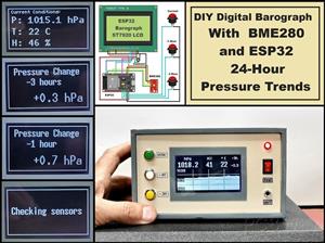 DIY Digital Barograph with BME280 and ESP32 - 24 Hour Pressure Trends
A barograph is a self-recording barometer that continuously measures and records atmospheric pressu...
-
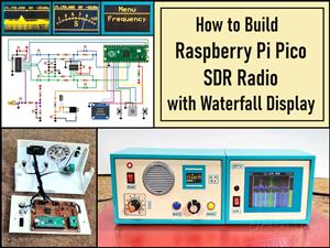 Build a Raspberry Pi Pico SDR Radio with Waterfall Display
Software-defined radio (SDR) is a radio communication system where components that have traditional...
-
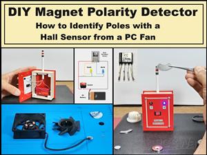 DIY Magnet Polarity Detector - How to Identify Poles with a Hall Sensor from a PC Fan
Recently, while working on a project, I needed to determine the polarity of several permanent magne...
-
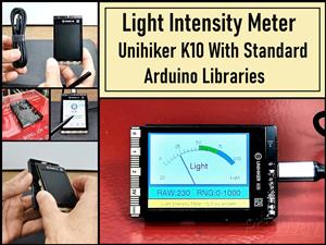 Light Meter Project - Making Dfrobot Unihiker K10 Work with Standard Arduino Libraries
The other day I received a shipment with a UNIHIKER K10 development board from DFRobot, which I rec...
-
-
AEL-2011 Power Supply Module
555 0 2 -
AEL-2011 50W Power Amplifier
514 0 2 -
-
-
Custom Mechanical Keyboard
710 0 0 -
Tester for Touch Screen Digitizer without using microcontroller
340 2 2 -
Audio reactive glow LED wristband/bracelet with NFC / RFID-Tags
322 0 1 -
-
-


