|
arduino IDEArduino
|
|

|
MIT App InventorMIT
|
Arduino Based Table Tennis Robot V1 DIY
About
This project is about a TTR(Table Tennis Robot) made at home with cardboard and wood, using some electronics and Arduino. I found various videos and get inspired because the interactivity of this robot, the Table Tennis sport and the call to action this machine produce is awesome.
I am happy for this TTR DIY, and really gave me a lot of fun. Even I was looking for a lot of mechanics I tried to use arduino and electronics and one App, developed with MIT APP Inventor, as the Basis of Design.
Aesthetics and finishings could have deficiencies: a lot of glue, everywhere, some card board recycled, tapes and pieces on wood as simple as possible. Material cost estimated in 60US$.As always man labour cost is hard to estimate because I enjoy doing projects as hobbist.
Steps
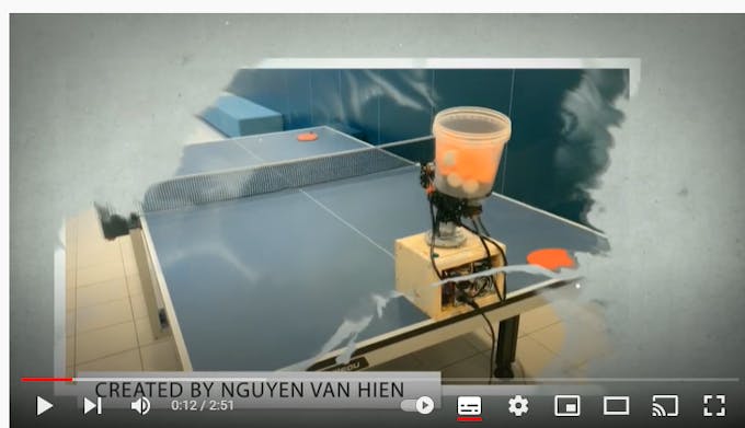
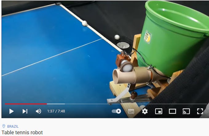
Step 1:Survey, Check a lot of other TTR models availables on internet to establish a concept for design(Basis of Design)
TTR model 1
TTR model 2
TTR model 3
Step 2: To establish location for the balls feeder as center of the design- Stepper motor o motor with gears are options. I decided stepper, after check, for make easy the controls in the development (it is no as true and real as I was thinking at the start).

Balls feeder location
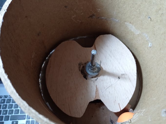
Ball feeder internal
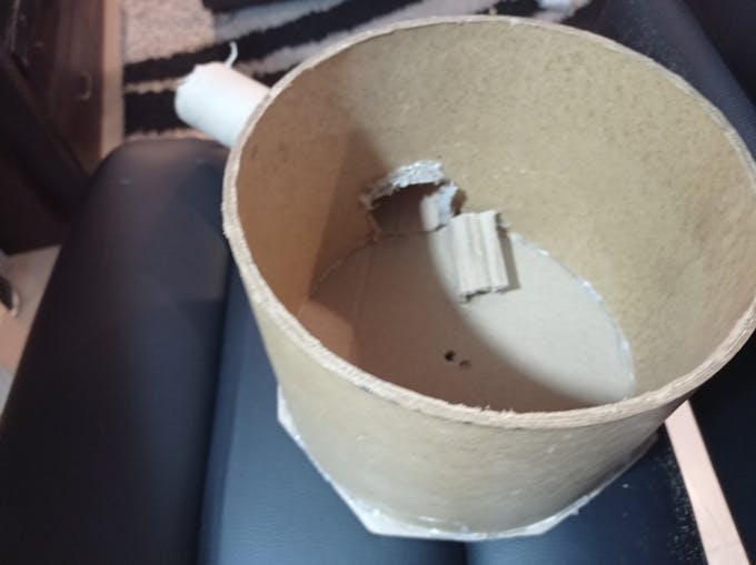
Ball's path should be blocked
Glue and glue
Step 3: Define the outlet duct section location and capabilites to move left/right/center , be careful selecting this location because tangent is quite importat to avoid ball stucked and overload for the ball feeder motor. In this case,the oultet hole of the feeder was no correct and this request torque in excess to the stepper motor, producing stucking of balls.
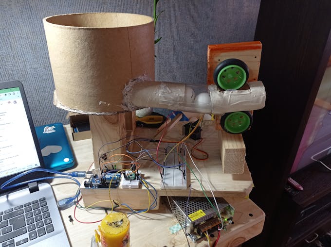
outlet Duct
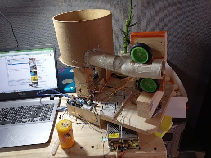
outlet duct strategy -failed!!

Duct cannot move lef right easily-even clear material is flexible
Balls stucked on oscilation mode
Step 4: Define strategy to move the section duct in order to get different directions of the ball. Wide Output angle for the ball will give us a lot of option to play with this TTR. However there is a angle limit constrained by de dimensions of the table and the location of the robot.
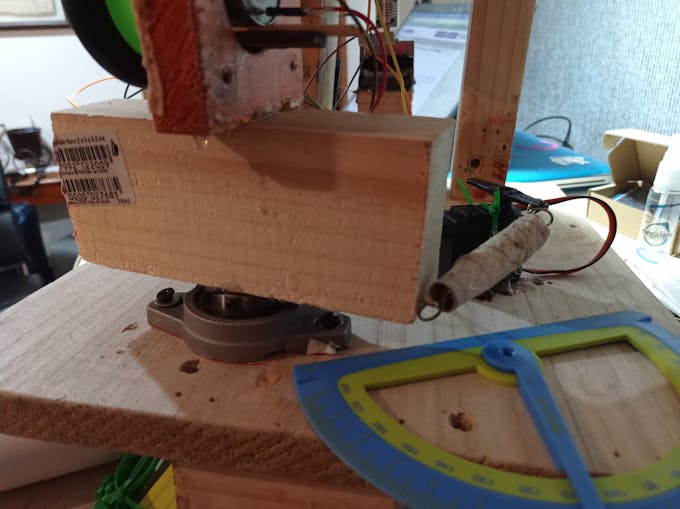
Piece of wood adhered to one FL004 bearing

Servo with a spring rigid give as the angle fixed and the oscilation mode
Step 5: Define motors location to produce the spin effect and launch the balls
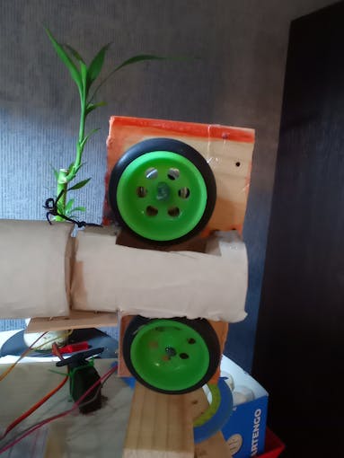
Motors should have more than 12000 rpm

Motor are controlled by one H bridge
Step 6: Electronics

Power supply-Power Level reductor-Arduino UNO
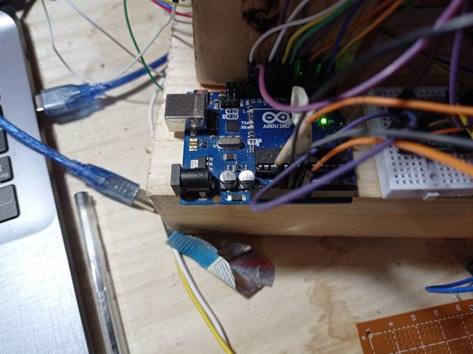
Arduino Uno
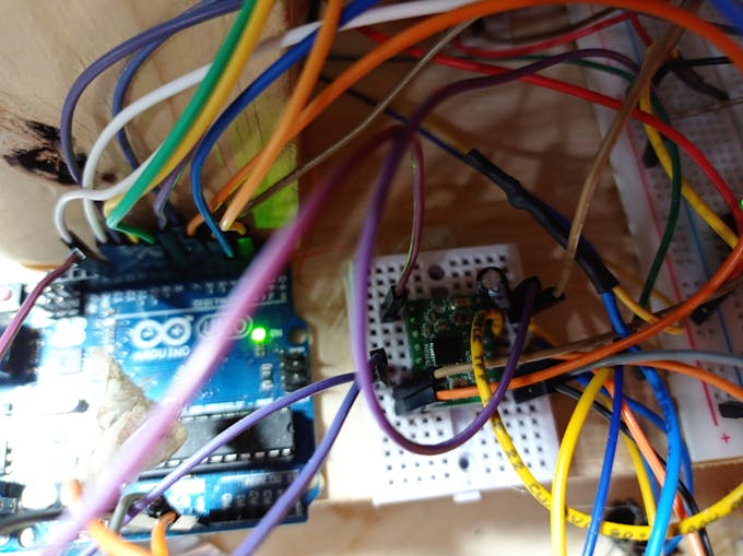
Stepper motor Drive A4998
Bluetooth HC-05 module
H bridge to control the two launcher's motors
Step 7: Integration
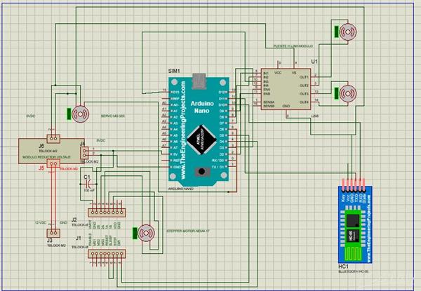
The TTR is controlled by the electronics devices, arduino and one APP developed FFP(fit for porpuse)
TTR Integration
Step 8: APP
Surfing the APP V1.0
Step 9: Field Test ( A lot of fun and interactivity)
Action for Fun #1
No Table available
Action for Fun # 2
Kids practice
Action for Fun # 3 - Balls and more balls operations
Robot Operations-Running
Action for Fun # 4. Table
This is the video in a table ( training-Field tests)
Bill of Materials
(1) Arduino UNO
(2) dc motors 12v-12000 rpm
(1) servo Motor
(1) 5VDC realy module
(1) DC gear motor
(1)Bluetooth Module HC-05
(1) Power source - 12VDC-5 to 10 Amp
(1) L298 H Bridge
(1) Nema 17 stepper Motor
Jumpers, glue, screws and meditation
Paper Bucket
Wood for the structure and Base
//* Ping Pong Robot Inicio de codigo: version 1- Julio 28-2022
// *  by hernando Bolaños
// *
// * 01-08-2022- servo variacion update
//* Pruebas  comunicaciones con APP
//*15-08-2022 , agregar botones de iz-centro-derecha y random - reciben pero interfieren con servo en oscilación
//*15-08-2022 -primeras pruebas de sliders- no operan correctamente con parseint() -debido a que estamos trabajando con multitasking
//*29-08-2022 - Settings-segun pruebas - revisar problema de entrada en hibernacion del BTh


//////////////////////////////////////////////////////////////////////////////////////////////////////
////WARNING: DRAFT CODE////The robot must need adult supervision if are kids playing with it
/////////////////////////////////////////////////////////////////////////////////////////////////////
//-- Zona de librerías --
// Comunicación serie por software
#include <SoftwareSerial.h>


//-- Zona de definiciones --
#define LED
#define RX 11
#define TX 10
const int pinENA = 3; // Motor UP PWM
const int pinIN1 = 2;// motor UP
const int pinIN2 = 7; // Motor UP
const int pinENB = 9;// Motor Down PWM
const int pinIN3 = 8;//Motor Down
const int pinIN4 = 13;//Motor Down

const int speed = 250;      //velocidad de giro 80% (200 de 255)

const int speedoff = 0;      //velocidad de giro 0% (0 de 255)

long unsigned valor=0;


//-- Zona de variables globales
SoftwareSerial BT1(RX,TX);

#define STEP_L 4    // pin STEP de A4988 a pin 4manejando la cara left del cubo
#define DIR_L 5     // pin DIR de A4988 a pin 5  manejandola cara left del cubo
#define ENAB 12     // pIN ENAB
int pasos = 200;    // LATERALES pasos   90 grados con motor Hanpose 17HS3430 : 1.8 grados por paso en condicion Full step- Se probo comportamiento en otras configuraciones de pasos
int tiempo_step = 1800; //es invertido-entre menos es el valor mas rapido va el stepper a variar con HMI - microseconds -segun DS minimo tiempo permitido del step de motores 1 microsegundo

//

#include <Servo.h>

Servo myservo;  // create servo object to control a servo
int servo_angle = 90;//90
int servo_angle1 = 60;// valor para quedar en posicion central fija
int variacion = 10;/// con esta variable se puede hacer mas lenta o mas rapida la osiclacion
unsigned long startTime_servo = 0;
unsigned long interval_servo = 1100;//t1100
int latchball = 0;
int latchservo = 0;
int latchup = 0;
int latchdown =0;
int latchservoizq =0;
int latchservocen =0;
int latchservoder =0;
int latchservorandom =0;
String dataIn = "";
int speedup=180;
int speeddown=180;


void setup()
{

  pinMode(STEP_L, OUTPUT);  // pin 4 como salida
  pinMode(DIR_L, OUTPUT);   // pin 5 como salida
  pinMode(ENAB, OUTPUT);  // pIN 12 como salida para driver A4998
  pinMode(pinIN1, OUTPUT);
  pinMode(pinIN2, OUTPUT);
  pinMode(pinENA, OUTPUT);//PWM
  pinMode(pinIN3, OUTPUT);
  pinMode(pinIN4, OUTPUT);
  pinMode(pinENB, OUTPUT);//PWM

  myservo.attach(6);  // attaches the servo on pin 6 to the servo object
  Serial.begin(9600);

myservo.write(90); // usado al inicio para verificar si el servo esta activo
myservo.write (0); // ir a posicion de inicio en el centro
myservo.write(60); // usado al inicio para verificar si el servo esta activo


BT1.begin(9600);
char recibido=0;
int i=0;
}


void loop()
{


unsigned currentTime = millis();
char recibido=0;

//int speedup = 0;

//int speeddown = 0;


//Si se ha recibido un dato
  if(BT1.available()==true){
     recibido=BT1.read(); //Se carga en la variable recibido
     Serial.print(recibido,0);
     //dataIn =  BT1.readString();
      //Serial.print(dataIn);

    // if (dataIn.startsWith ("s3")){
     //String dataInS= dataIn.substring(2,dataIn.length());
    //int speedup = dataInS.toInt();}

     //if (dataIn.startsWith ("s4")){
     //String dataInS= dataIn.substring(2,dataIn.length());
     //int speeddown = dataInS.toInt();}


//Serial.print(speedup);

//Serial.print(speeddown);
     }


//


if (recibido == 'A'){

    int latchrobot = 1;

Serial.print("Robot Activado");

}


if (recibido == 'B'){

    int latchrobot = 0;

Serial.println("Robot Desactivado");

latchball = 0; //desenganchar
latchservo =0; //desenganchar
latchup=0;//desenganchar
latchdown=0;//desenganchar
latchservoizq=0;//desenganchar
latchservoder=0;//desenganchar
latchservocen=0;//desengachar
digitalWrite(ENAB, HIGH); //aplicar  Modo Disable del driver

   }


if (recibido == 'C'){

latchball= 1;}


if (recibido == 'D'){

latchball= 0;}


if (recibido == 'E'){

latchup= 1;}


if (recibido == 'F'){

latchup= 0;}

if (recibido == 'G'){

latchdown= 1;}


if (recibido == 'H'){

latchdown= 0;}


if (recibido == 'I'){

latchservo = 1;}

if (recibido == 'J'){

latchservo = 0;}


if (recibido == 'Z'){

latchservoizq = 1;}

if (recibido == 'W'){

latchservoizq = 0;}

if (recibido == 'T'){

latchservocen = 1;}

if (recibido == 'X'){

latchservocen = 0;}


if (recibido == 'R'){

latchservoder = 1;}

if (recibido == 'Y'){

latchservoder = 0;}


if (recibido == 'M'){

latchservorandom = 1;}

if (recibido == 'N'){

latchservorandom = 0;}

//if (((valor >=20) and (valor <=25)) and(( latchup=1) and (latchdown =1) )){ const int speed=valor; Serial.print(speed);} // tomando trama de los slider up y down


if (latchball == 1){
      //Serial.print("Dispensar Bolas activado");
        alimbolas();
        //BT1.write('C');

     }


if (latchball  == 0){
      //Serial.println("parar Dispensar Bolas activado");
                //BT1.write('D');

     }


if (latchservo == 1){

      //Serial.print("Oscilar activado");
        oscilar();
        //BT1.write('I');}

}

if (latchservo == 0){

      //Serial.println("Oscilar desactivado");

        //BT1.write('J');

   }


if (latchup == 1){


 uprob();

}

if (latchup == 0){

upoff();
//Serial. println("Up desactivado)
//BTI.write(' ');

}

if (latchdown == 1){

down();

}

if (latchdown == 0){

downoff();
//Serial. println("Up desactivado)
//BTI.write(' ');

}


if (latchservoizq== 1){

//
int i=0;

for (int i = 0; i <= 1; i++) {
  oscizq();
  }

if (i>=1){
latchservoizq == 0;}
//Serial.println("Fijo en izquierda Activado");
//BTI.write(' ');

}

if (latchservoizq == 0){

//oscizqoff();
//Serial. println(" Fijo en ziquiera desActivado")
//BTI.write(' ');

}

if (latchservocen== 1){

int i=0;


for (int i = 0; i <= 1; i++) {
  osccentro();
  }

if (i>=1){
latchservocen == 0;}
//Serial. println("Fijo en centro Activado");
//BTI.write(' ');


}

if (latchservocen == 0){

//osccentrooff();
//Serial. println(" Fijo en centro desaActivado)
//BTI.write(' ');

}


if (latchservoder== 1){

int i=0;

for (int i = 0; i <= 1; i++) {
 oscder();
  }
if (i>=1){
latchservoder == 0;}
//Serial.println("Fijo en centro Activado");
//BTI.write(' ');

}

if (latchservoder == 0){

 //oscderoff();

//Serial. println(" Fijo en centro desaActivado)
//BTI.write(' ');

}
}


void alimbolas()// alimenta bolas giando en sentido NCW

{

//Serial.print("Bolas NCW,");

  digitalWrite(ENAB, LOW); // Modo Enable del driver

  digitalWrite(DIR_L, HIGH);    // giro en  sentido NCW
  for (int i = 0; i < pasos; i++) {   //
    digitalWrite(STEP_L, HIGH);       // nivel alto
    delayMicroseconds(tiempo_step);          // por x mseg
    delayMicroseconds(tiempo_step);
    digitalWrite(STEP_L, LOW);        // nivel bajo
    delayMicroseconds(tiempo_step);          // por x mseg
    delayMicroseconds(tiempo_step);
  }

}


void oscilar() //activa modo  oscilar en el robot - izquierda a derecha
{
  unsigned currentTime = millis();


  //Serial.println("servo");
    if (currentTime - startTime_servo >= interval_servo){
      startTime_servo=currentTime;
      myservo.write(servo_angle);
      servo_angle = servo_angle + variacion;
      if (servo_angle == 150) servo_angle = 30;
     //Serial.println(servo_angle);
    }
}


void oscizq() //activa modo  oscilar en el robot - izquierda a derecha
{
  unsigned currentTime = millis();


  //Serial.println("servo");
    if (currentTime - startTime_servo >= interval_servo){
      startTime_servo=currentTime;
      myservo.write(160);

     //Serial.println(servo_angle);
    }
}


void oscder() //activa modo  oscilar en el robot - izquierda a derecha
{
  unsigned currentTime = millis();


  //Serial.println("servo");
    if (currentTime - startTime_servo >= interval_servo){
      startTime_servo=currentTime;
      myservo.write(0);

    }
}


void osccentro() //activa modo  oscilar en el robot - izquierda a derecha
{
  unsigned currentTime = millis();


  //Serial.println("servo");
    if (currentTime - startTime_servo >= interval_servo){
      startTime_servo=currentTime;
      myservo.write(90);

    }
}


void oscizqoff() //activa modo  oscilar en el robot - izquierda a derecha
{
  unsigned currentTime = millis();


  //Serial.println("servo");
    if (currentTime - startTime_servo >= interval_servo){
      startTime_servo=currentTime;
      myservo.write(90);

     //Serial.println(servo_angle);
    }
}


void oscderoff() //activa modo  oscilar en el robot - izquierda a derecha
{
  unsigned currentTime = millis();


  //Serial.println("servo");
    if (currentTime - startTime_servo >= interval_servo){
      startTime_servo=currentTime;
      myservo.write(90);

    }
}


void osccentrooff() //activa modo  oscilar en el robot - izquierda a derecha
{
  unsigned currentTime = millis();


  //Serial.println("servo");
    if (currentTime - startTime_servo >= interval_servo){
      startTime_servo=currentTime;
      myservo.write(90);

    }
}


void uprob()  //
{
  //Serial.println("corriendo rutina UP,");
 //  Serial.println(speedup);
   digitalWrite(pinIN1, HIGH);
   digitalWrite(pinIN2, LOW);
   analogWrite(pinENA, speedup);
   //delay(1000);
}


void upoff()
{ //Serial.println("corriendo rutina upoff");

   digitalWrite(pinIN1, LOW);
   digitalWrite(pinIN2, LOW);
   analogWrite(pinENA, speedoff);
   //delay(1000);
}


void down()
{
   digitalWrite(pinIN3, LOW);
   digitalWrite(pinIN4, HIGH);
   analogWrite(pinENB, speeddown);
   //delay(1000);
}


void downoff()
{
   digitalWrite(pinIN3, LOW);
   digitalWrite(pinIN4, LOW);
   analogWrite(pinENB, speedoff);
   //delay(1000);
}
Arduino Based Table Tennis Robot V1 DIY
- Comments(2)
- Likes(2)
- 0 USER VOTES
- YOUR VOTE 0.00 0.00
- 1
- 2
- 3
- 4
- 5
- 6
- 7
- 8
- 9
- 10
- 1
- 2
- 3
- 4
- 5
- 6
- 7
- 8
- 9
- 10
- 1
- 2
- 3
- 4
- 5
- 6
- 7
- 8
- 9
- 10
- 1
- 2
- 3
- 4
- 5
- 6
- 7
- 8
- 9
- 10
 More by Bolaños Hernando
-
 How to built a Hybrid Bike Computer
Hybrid Bike ComputerThis PCB is a Cheap solution to track your training preformanceBased o esp32 , r...
-
 My nunchuck adapter (PCB) for my Galagino Retro console_Running on a ESP32 device
Galagino is an open source idea of hardware and software from Tiil Harbaum (https://github.com/harba...
-
 PCB DESIGN FOR BIKE COMPUTER DIY
PCB DESIGN FOR A BIKE COMPUTER DIY - QBIKOThis PCB was designed to run a BIke computer based on ESP3...
-
 How to build a Mecanum Wheels Robot with an Arduino Mega and a PCB
Once I finished my first version of this robot I found it interesting to develop a PCB, mount and so...
-
 How to build a Bike computer DIY-Heart Rate sensor comparison and selection
This project is about a tutorial to evaluate 3 hear rate Sensor. In this way I will choose the bette...
-
 How to build a Bike computer with a ESP32 -WROOM + 2 Reed Switches + 1 Cellular Phone(old with GPS and BTH)
The complete tutorial explaining all the details for this project, can be watched in the next vide...
-
 How to build a Table Tennis Robot - V2
Story: Once I finished my first protoype for a TTR , I recognize and learnt about a lot of improveme...
-
 How to build a Mecanum Wheels Robot_V1
The storyHow to bulild a Robot usually is an assay and error process, you can see my first prototype...
-
 How to use AI to program a 2DOF ROBOT- Arduino+ pyhton+opencv+chatgp+ps3eyecam
The challenge was to obtanin a mix of code generated by chatgpt for pyhton, opencv, and arduino and ...
-
 Node MCU based Wi Fi Servo Switch- DIY
About:Regulations usually forbide to introduce pieces of equipment in the conecctions and wiring of ...
-
 CNC_DIY_LASER_PLOTTER_VYNIL CUTTER
ABOUT THIS PROJECTSummaryTo develop a CNC need you to learn about code, IT, electricity, electronics...
-
 Arduino Based Table Tennis Robot V1 DIY
AboutThis project is about a TTR(Table Tennis Robot) made at home with cardboard and wood, using som...
-
 Robot Arm to implement CV projects
StoryFour years ago I was looking for a good robot arm, this year I have time and decided to replica...
-
 MINI ROBOT ARM
 - YouTubeIdea based on Tutorials shared by Mr. Pinaut for :software -schematics -inst...
MINI ROBOT ARM
MINI ROBOT ARM - YouTubeIdea based on Tutorials shared by Mr. Pinaut for :software -schematics -inst...
-
 Bluetooth Controlled LEGO Toy Car
MotivationMy motivation was my kids. I want to share time and have fun with them teaching them some ...
-
 Integrated HOME Irrigation System
Motivation:Since I left the university, 24 years ago, I haven't had the chance to update my knowledg...
-
 Rubik's Cube Solver Robot DIY - V.3.0
Scope of the projectThe idea was to build a Rubik's cube solver robot, as simple as possible, easy t...
-
 Rubik's Cube Solver Robot v1
The drivers to develop my project were:Rubik′s cube is a "best seller" category toy, more than 350 m...
-
-
mammoth-3D SLM Voron Toolhead – Manual Drill & Tap Edition
162 0 0 -
-
AEL-2011 Power Supply Module
678 0 2 -
AEL-2011 50W Power Amplifier
581 0 2 -
-
-
Custom Mechanical Keyboard
782 0 0 -
Tester for Touch Screen Digitizer without using microcontroller
406 2 2 -
Audio reactive glow LED wristband/bracelet with NFC / RFID-Tags
368 0 1 -
-


