|
|
ESP8266EXESPRESSIF
|
x 1 | |

|
I2C IIC Serial 128x64 OLED Display Module |
x 1 |

|
arduino IDEArduino
|
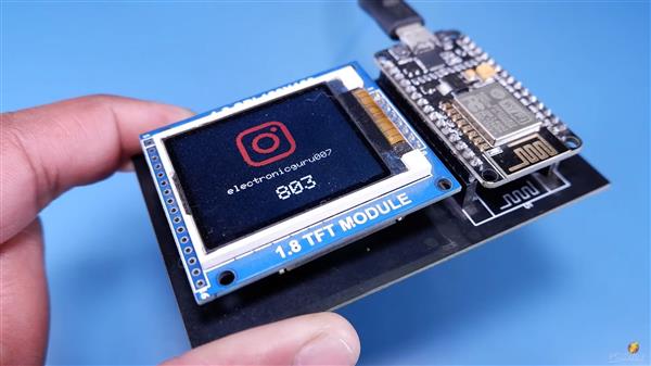
Live Instagram Followers Pcb
ESP8266 is capable of functioning reliably in industrial environments, with an operating temperature ranging from –40°C to +125°C. Powered by advanced calibration circuitries, ESP8266 can dynamically remove external circuit imperfections and adapt to changes in external conditions. It is highly-integrated with in-built antenna switches, RF balun, power amplifier, low-noise receive amplifier, filters, and power management modules. ESP8266 adds priceless functionality and versatility to your applications with minimal Printed Circuit Board (PCB) requirements.
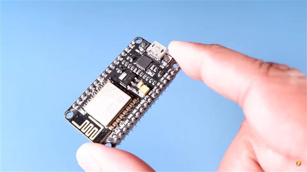
Check out the examples for how to use it, no API key needed.
This library is getting the data directly from Instagram, but it is not using their API. The API is pretty complicated to get access tokens for but I found some information here for a way to get JSON from public facing pages
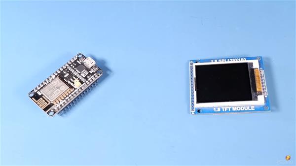
Wireless interfacing, connecting to the web and remote controlling are features that can be very helpful in many projects. ESP-8266 is a low-cost microchip with full TCP/IP (Transmission Control Protocol and Internet Protocol), 32-bit MCU, 10-bit ADC and different interfaces like PWM, HSPI and I2C that enables microcontrollers to connect to the Wi-Fi networks. It is one of the best solutions for adding wifi to projects and (but not the only one.)
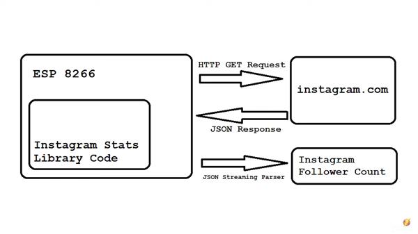
ESP-01 is the first module that comes for esp-8266 and it has just two GPIO pin and needs 3.3V for power. It doesn’t have a regulator, so make sure to have a reliable power supply. It doesn’t have a converter, therefore you need USB to TTL convertor. Converter for this module (and also other models of ESP) should be in 3.3V mode. The reason for this is the convertor will make 0 and 1 via pulses, and voltage of these pulses should be recognizable for ESP, so check this before buying. Because of the limited quantity GPIO pins and also their low current (12mA per each one), we may need more pins or more current;
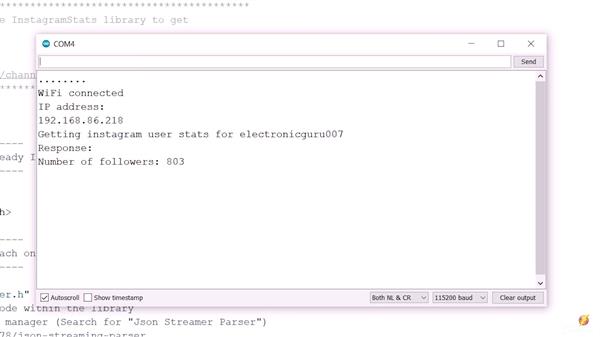
so we can easily use Arduino with a module to access its IO pins (another way to access more GPIO pins is wiring out a very thin wire on the chip to the pin headers you need, but its not a good and safe solution). If you don’t want to use another board, you can design or use a circuit to increase current.
In this project, We want to connect ESP-01 to the Internet and get some data from Instagram pages. Then we send the data to Arduino and after processing it, Arduino changes the location of Servo pointer according to data. Let’s do it.
Circuit
This microchip comes with different types of module like ESP-01, ESP-12 or other development boards and breakouts like NodeMCU devkit, Wemos and Adafruit Huzzah. The difference is their pins, components needed for easier usage and also price. The microchip has 32 pins that 16 pins of it are GPIO; depending on the model, the number of GPIOs provided is different. For ESP-01 it is just two pins but other models like breakouts have all of them. When using ESP-8266,
you will need a serial interface to communicate and program. Simple modules usually don’t have serial converter (FTDI is usually suggested but other converters can be used, too) and it should be provided separately. Regulators, built-in LEDs, and pull-up or down resistors are other features that some models may have; the lowest cost between all of these modules is for ESP-01 and it’s our choice now.
Now its time to upload the ESP-01 code. We want to use Arduino IDE to upload the sketch to ESP. Before uploading the code, you should select ESP board for IDE.
Go to File>Preferences and put http://arduino.esp8266.com/stable/package_esp8266com_index.json in the additional boards. Then download and install it. Now you can see the ESP boards in Tools>Board. Select “Generic ESP8266 Module” and copy the code in a new sketch. Download the “InstagramStats” library and add it to IDE. Note that we have modified the library, So you should download it here. Then you should set USB to TTL Converter as Uploader hardware. Just plug the converter in and set the right port in Tools>Port. It’s ready to Upload.
#include <Wire.h>                   // Only needed for Arduino 1.6.5 and earlier
#include "SSD1306.h"                // alias for `#include "SSD1306Wire.h"`
#include <WiFi.h>
#include <NTPClient.h>
#include <WiFiUdp.h>
#include <HTTPClient.h>
#include <Adafruit_GFX.h>           // https://github.com/adafruit/Adafruit-GFX-Library
#include "Adafruit_LEDBackpack.h"   // https://github.com/adafruit/Adafruit_LED_Backpack
#include <ArduinoJson.h>            // https://github.com/bblanchon/ArduinoJson
#include "InstagramStats.h"         // https://github.com/witnessmenow/arduino-instagram-stats
#include "JsonStreamingParser.h"    // https://github.com/squix78/json-streaming-parser
#include <WiFiClientSecure.h>

#define NTP_OFFSET  +2  * 60 * 60       // segundos
#define NTP_INTERVAL 60 * 1000          // milissegundos
#define NTP_ADDRESS  "0.pool.ntp.org"   // Url NTP
#define SDA_PIN 5                       // GPIO5 -> SDA
#define SCL_PIN 4                       // GPIO4 -> SCL
#define SSD_ADDRESS 0x3c                // i2c

char string[25];

const char* ssid       = "Your-WIFI-SSID";
const char* password   = "Your-WIFI-Password";

String formattedTime;
String ipStr;
String text;

WiFiUDP ntpUDP;
NTPClient timeClient(ntpUDP, NTP_ADDRESS, NTP_OFFSET, NTP_INTERVAL);
SSD1306  display(SSD_ADDRESS, SDA_PIN, SCL_PIN);

WiFiClientSecure secureClient;
WiFiClient client;

InstagramStats instaStats(secureClient);

String userName = "Your-INSTAGRAM-username";
String stats;

unsigned long api_delay = 1 * 60000; //time between api requests (1mins)
unsigned long api_due_time;

void setup()
{
  Serial.begin(115200);
  Serial.println("");
  Serial.println("ESP32 Instagram Stats");
  Serial.println("");

  display.init();
//  display.flipScreenVertically();
  display.setTextAlignment(TEXT_ALIGN_LEFT);
  display.setFont(ArialMT_Plain_10);

  connectWiFi();
  timeClient.begin();
  InstagramUserStats response = instaStats.getUserStats(userName);
  text = (String) response.followedByCount;
}

void loop()
{
  timeClient.update();
  formattedTime = timeClient.getFormattedTime();
  Serial.print("TIME: ");
  Serial.println(formattedTime);
  if(timeClient.getMinutes() == 00)   //updates every hour.
  {
    Serial.print("The number of Instagram followers of user " + userName + " is: ");
    InstagramUserStats response = instaStats.getUserStats(userName);
    Serial.println(response.followedByCount);
    text = (String) response.followedByCount;
  }
  display.clear();
  display.setFont(ArialMT_Plain_24);
  display.drawString(17, 0,  formattedTime);
  display.setFont(ArialMT_Plain_10);
  display.drawString(0, 25,  "Instagram: ");
  display.drawString(60, 25,  userName);
  display.setFont(ArialMT_Plain_24);
  display.drawString(40, 35,  text);
  display.display();
  delay(1000);
}

void connectWiFi(void)
{
  int i;
  Serial.println();
  Serial.print("Connecting to: ");
  Serial.println(ssid);
  display.drawString(2, 10, "Connected to: ");
  display.drawString(1, 25, String(ssid));
  display.display();
  WiFi.begin(ssid, password);
  while ((WiFi.status() != WL_CONNECTED) && i < 100)
  {
    i ++;
    delay(500);
    Serial.print(".");
    display.drawString((3 + i * 2), 35, "." );
    display.display();
  }
  if ( WiFi.status() == WL_CONNECTED)
  {
    IPAddress ip = WiFi.localIP();
    ipStr = String(ip[0]) + '.' + String(ip[1]) + '.' + String(ip[2]) + '.' + String(ip[3]);
    display.clear();
    display.setFont(ArialMT_Plain_16);
    display.drawString(0, 0, "WiFi Connected!");
    display.drawString(0, 25, ipStr);
    Serial.println("");
    Serial.println("WiFi Connedcted.");
    Serial.println("IP address: ");
    Serial.println(WiFi.localIP());
    Serial.print("Subnet Mask: ");
    Serial.println(WiFi.subnetMask());
    Serial.print("Gateway: ");
    Serial.println(WiFi.gatewayIP());
    display.display();
  }
  else
  {
    ipStr = "NOT CONNECTED";
    display.clear();
    display.setFont(ArialMT_Plain_16);
    display.drawString(0, 0,  "WiFi not connected.");
    display.drawString(0, 25, ipStr);
    Serial.println("");
    Serial.println("WiFi not connected.");
    display.display();
  }
  delay(1000);
}
Live Instagram Followers Pcb
- Comments(0)
- Likes(2)
- 0 USER VOTES
- YOUR VOTE 0.00 0.00
- 1
- 2
- 3
- 4
- 5
- 6
- 7
- 8
- 9
- 10
- 1
- 2
- 3
- 4
- 5
- 6
- 7
- 8
- 9
- 10
- 1
- 2
- 3
- 4
- 5
- 6
- 7
- 8
- 9
- 10
- 1
- 2
- 3
- 4
- 5
- 6
- 7
- 8
- 9
- 10
 More by electronicguru0007
-
 How to make an alarm clock with pic microcontroller
he five push buttons will act as an input for setting the alarm for the required time. So one end of...
-
 How to make RMS to DC Converter using IC AD736
A True-RMS or TRMS is a type of converter which converts RMS value to equivalent DC value. Here in t...
-
 STM32 SPI Communcation and Data Sent
SPI in STM32F103C8Comparing SPI bus in Arduino & STM32F103C8 Blue Pill board, STM32 has 2 SPI bu...
-
 How to Communicate Arduinos via RS-485
What project will you develop?The project consists of 3 Arduino's. We have an Arduino UNO, a Nano, a...
-
 PIC16F877A Temperature and Humidity Measurement Board
Temperature and Humidity measurement is often useful in many applications like Home Automation, Envi...
-
 Diy Buck Converter
n the field of DC-DC Converters, A single-ended primary-inductor converter or SEPIC converter is a t...
-
 Iot AC Current Measuring System
Smart power monitoring is getting increasingly popular to improve energy efficiency in medium/small ...
-
 ESP32 Weather Station
In this project, we will learn how to create a weather station, which will display reading from a BM...
-
 NRF Data Transfer Via 2 Boards
There are various wireless communication technologies used in building IoT applications and RF (Radi...
-
 Iot patient monitoring system
When we are talking about major vital signs of a human body, there are four major parameters that we...
-
 Setting up zigbee communication with nodemcu and arduino
Zigbee is a popular wireless communication protocol used to transfer a small amount of data with ver...
-
 Ac Dimmer Remote PCB
The brightness can be controlled using the IR remote of TV, DVD, etc. Dimming Control system using M...
-
 Esp32 Home Automation
There are relay modules whose electromagnet can be powered by 5V and with 3.3V. Both can be used wit...
-
 Lora Communication With Network
This was a very simple project and can come in handy for various applications. But what it can't do ...
-
 GPS Module Based Tracking Device Pcb
ESP32 GPS vehicle tracker using NEO 6M GPS module and Arduino IDE. With the help of this GPS tracker...
-
 Traffic Management for Emergency Vehicles using AT89S52 Microcontroller
These days’ traffic congestion is the biggest problem of densely populated cities. The project focus...
-
 Diy Multimeter Pcb
This is a project based on Arduino board which can measureresistance, diode, continuity[H1] , voltag...
-
 Live Instagram Followers Pcb
ESP8266 is capable of functioning reliably in industrial environments, with an operating temperature...
-
-
mammoth-3D SLM Voron Toolhead – Manual Drill & Tap Edition
229 0 0 -
-
AEL-2011 Power Supply Module
755 0 2 -
AEL-2011 50W Power Amplifier
627 0 2 -
-
-
Custom Mechanical Keyboard
822 0 0 -
Tester for Touch Screen Digitizer without using microcontroller
448 2 2 -
Audio reactive glow LED wristband/bracelet with NFC / RFID-Tags
399 0 1 -
-


