|
Arduino Web Editor |
Ac Dimmer Remote PCB
The brightness can be controlled using the IR remote of TV, DVD, etc. Dimming Control system using MOC3021, BT136 Triac and a zero-crossing detector circuit based on the MCT2E optocoupler. Optocoupler provides complete isolation between the AC side and the DC controller side. So if any fault or short circuit happens on the AC side will have no effect on the controller side.
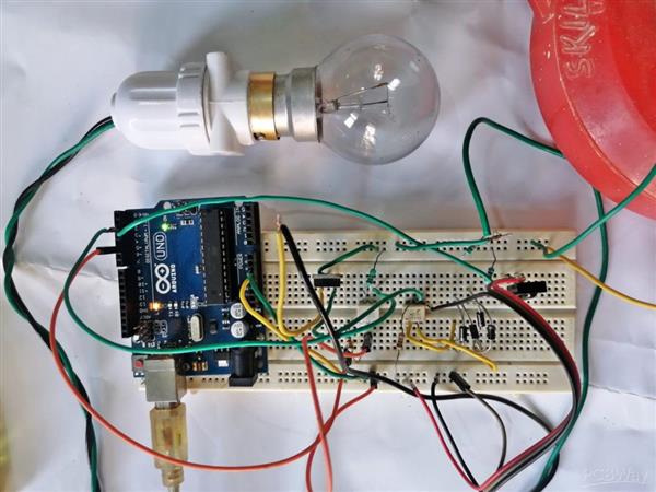
In this tutorial, we will design a circuit using TRIAC and optocoupler to make a 220V AC Light Dimmer or AC Fan Speed Controller using Arduino UNO. most of the home appliances are supplied with the AC mains power. Sometimes we need to control the brightness of bulb or Speed of Fan/ AC Motor etc or any other dimming control for an instant. Controlling an AC load is not as easy as controlling a DC load. The AC mains with a sinusoidal wave have the frequency of 50Hz to 60 HZ.
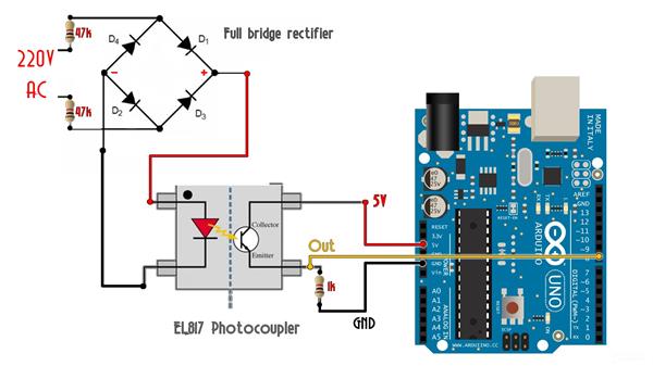
The most popular and proper way for Dimming of 230v AC is through phase control with a Triac. To build an AC dimmer, the zero-crossing detector circuit used and zero-crossing points (the points where the wave changes its polarity) are important. A zero-crossing detector is used to generate a sync pulse related to the AC voltage phase angle often used in power control circuits. Zero crossing detector basically detect zero voltage points and inform the controller or controller circuit. It helps to minimize high rate change of current with respect to time (dI/dt) as a result less heating and start-up current in the load which improves the lifetime of load such as motors. A Zero Crossing Detector can be designed in many ways like using transistor, using op-amp or using optocoupler IC
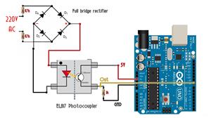
bridge rectifier converts ac into dc
Output of bridge rectifier is fed to opto-coupler
Led inside the optocoupler requires minimum of 1V to turn on
when ac wave goes near to the zero crossing line,ie below 1V led will turn off
as a result output transistor will turn of and pulled up to 5v

The zero-crossing technique is one of the methods enabling to evaluate the delay time of propagating waves.
In this project I’m going to show how to a remote used to control the circuit for the Dimmer, so that the lamp brightness is controlled from IR remote control instead of the potentiometer.
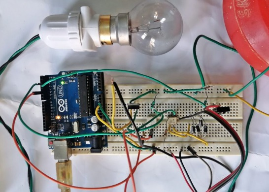
Connect the circuit as per the given schematic diagram. You can use DB107 or other bridge rectifier ic at the place of 4 separate 1N 4007 diodes. Here I use 2 55k resistor to limit the current from AC input to rectifier, an Optocoupler ic connected, here 4N35 is connected but you can use MCT2E or PC817 etc. In optocoupler ic there is an LED and NPN transistor. connect negative supply from bridge rectifier to pin 2, this is the negative pin of the LED of the optocoupler. the positive terminal of LED at pin 1 in this optocoupler. The emitter of the transistor is connected with the ground pin of Arduino and collector pin which is at pin 5 of optocoupler ic is directly connected with digital input pin of Arduino and one 10K resistor is with pin 5 is connected to +5v of Arduino, here this resistor is working as a pull-up resistor.
Schematic diagram
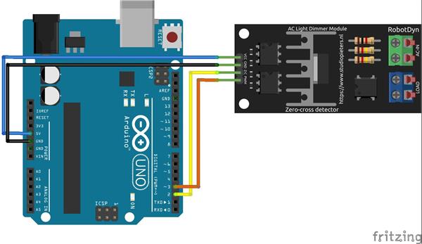
#include <IRremote.h>

int RECV_PIN = 2;

IRrecv irrecv(RECV_PIN);

decode_results results;

void setup()
{
  Serial.begin(9600);
  // In case the interrupt driver crashes on setup, give a clue
  // to the user what's going on.
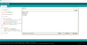
  Serial.println("Enabling IRin");
  irrecv.enableIRIn(); // Start the receiver
  Serial.println("Enabled IRin");
}

void loop() {
  if (irrecv.decode(&results)) {
    Serial.println(results.value, DEC);
    irrecv.resume(); // Receive the next value
  }
  delay(150);
}

Ac Dimmer Remote PCB
- Comments(0)
- Likes(0)
- 0 USER VOTES
- YOUR VOTE 0.00 0.00
- 1
- 2
- 3
- 4
- 5
- 6
- 7
- 8
- 9
- 10
- 1
- 2
- 3
- 4
- 5
- 6
- 7
- 8
- 9
- 10
- 1
- 2
- 3
- 4
- 5
- 6
- 7
- 8
- 9
- 10
- 1
- 2
- 3
- 4
- 5
- 6
- 7
- 8
- 9
- 10
 More by electronicguru0007
-
 How to make an alarm clock with pic microcontroller
he five push buttons will act as an input for setting the alarm for the required time. So one end of...
-
 How to make RMS to DC Converter using IC AD736
A True-RMS or TRMS is a type of converter which converts RMS value to equivalent DC value. Here in t...
-
 STM32 SPI Communcation and Data Sent
SPI in STM32F103C8Comparing SPI bus in Arduino & STM32F103C8 Blue Pill board, STM32 has 2 SPI bu...
-
 How to Communicate Arduinos via RS-485
What project will you develop?The project consists of 3 Arduino's. We have an Arduino UNO, a Nano, a...
-
 PIC16F877A Temperature and Humidity Measurement Board
Temperature and Humidity measurement is often useful in many applications like Home Automation, Envi...
-
 Diy Buck Converter
n the field of DC-DC Converters, A single-ended primary-inductor converter or SEPIC converter is a t...
-
 Iot AC Current Measuring System
Smart power monitoring is getting increasingly popular to improve energy efficiency in medium/small ...
-
 ESP32 Weather Station
In this project, we will learn how to create a weather station, which will display reading from a BM...
-
 NRF Data Transfer Via 2 Boards
There are various wireless communication technologies used in building IoT applications and RF (Radi...
-
 Iot patient monitoring system
When we are talking about major vital signs of a human body, there are four major parameters that we...
-
 Setting up zigbee communication with nodemcu and arduino
Zigbee is a popular wireless communication protocol used to transfer a small amount of data with ver...
-
 Ac Dimmer Remote PCB
The brightness can be controlled using the IR remote of TV, DVD, etc. Dimming Control system using M...
-
 Esp32 Home Automation
There are relay modules whose electromagnet can be powered by 5V and with 3.3V. Both can be used wit...
-
 Lora Communication With Network
This was a very simple project and can come in handy for various applications. But what it can't do ...
-
 GPS Module Based Tracking Device Pcb
ESP32 GPS vehicle tracker using NEO 6M GPS module and Arduino IDE. With the help of this GPS tracker...
-
 Traffic Management for Emergency Vehicles using AT89S52 Microcontroller
These days’ traffic congestion is the biggest problem of densely populated cities. The project focus...
-
 Diy Multimeter Pcb
This is a project based on Arduino board which can measureresistance, diode, continuity[H1] , voltag...
-
 Live Instagram Followers Pcb
ESP8266 is capable of functioning reliably in industrial environments, with an operating temperature...
-
-
mammoth-3D SLM Voron Toolhead – Manual Drill & Tap Edition
88 0 0 -
-
AEL-2011 Power Supply Module
602 0 2 -
AEL-2011 50W Power Amplifier
542 0 2 -
-
-
Custom Mechanical Keyboard
746 0 0 -
Tester for Touch Screen Digitizer without using microcontroller
371 2 2 -
Audio reactive glow LED wristband/bracelet with NFC / RFID-Tags
346 0 1 -
-


