|
|
TS-23E01-T(C)14-#519PIC
|
x 1 | |

|
M41T94MQ6FSTMicroelectronics
|
x 1 | |

|
TPS63700DRCTTexas Instruments
|
x 1 | |
|
|
BL-PBZ09042C2703YBDongguan Bolin Elec
|
x 1 | |

|
L135-B475003500000Lumileds
|
x 1 |

|
Arduino Web Editor |
How to make an alarm clock with pic microcontroller

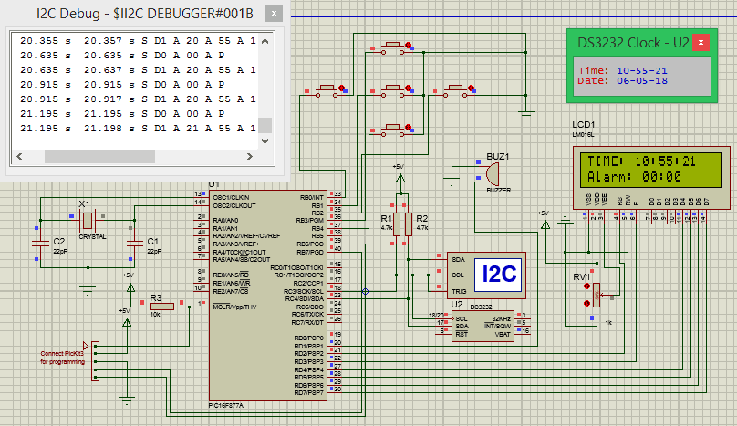
he five push buttons will act as an input for setting the alarm for the required time. So one end of all the push buttons are connected to ground and the other ends are connected to PORTB pin, internal pull-up resistor will be used on these pins to avoid the pins floating. The Buzzer will act as an output and will give us a beep when the alarm gets triggered and is connected to the PORT S pin. The current time is always kept in track by the DS3231 RTC module from which the PIC receives the data through I2C bus, so the SCL and SDA pins of the RTC module is connected to SCL and SDA pin of the PIC controller.

Before getting into the main program, we have to define the pins that we have used with more meaningful name. This way it will be easy to use them during programming. The pins defined in our program is shown below
//Define the LCD pins
#define RS RD2 //Reset pin of LCD
#define EN RD3 //Enable pin of LCD
#define D4 RD4 //Data bit 0 of LCD
#define D5 RD5 //Data bit 1 of LCD
#define D6 RD6 //Data bit 2 of LCD
#define D7 RD7 //Data bit 3 of LCD
//Define Buttons
#define MB RB1 //The middle button
#define LB RB0 //Left button
#define RB RB2 //Right button
#define UB RB3 //Upper Button
#define BB RB4 //Bottom button
//Define Buzz
#define BUZZ RD1 //Buzzer is connected to RD1
Inside the main function we start by declaring the Input and output pins. In our project the PORTB is used for push buttons which is an input device so we set their pins as inputs and PORTD is used for LCD and buzzer so we set their pins as Output. Also a pin should never be left floating meaning, the I/O pins should always be connected to either Ground or to the +5V voltage. In our case for the push buttons the pins will not be connected to anything when the button is not pressed so we use an internal pull-up resistor which sets the pin to High when not in use. This is done using the control registers as shown below
TRISD = 0x00; //Make Port D pins as outptu for LCD interfacing
TRISB = 0xFF; //Switchs are declared as input pins
OPTION_REG = 0b00000000; //Enable pull up Resistor on port B for switchs
BUZZ = 0; //Turn of buzzer
Simulation:
This program can also be simulated using the proteus software. Just re-create the circuit shown above and load the hex file into the PIC
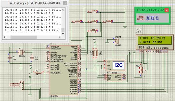
A screen shot taken during the simulation is shown below

The simulation becomes very useful when you are trying to add new features to the project. You can also use the I2C debugger module to check what data is going in and coming out through the I2C bus. You can try pressing the buttons and also set the alarm time. When the set time is equal to the current time then the buzzer will go high.
Working of Digital Alarm Clock using PIC16F877A:
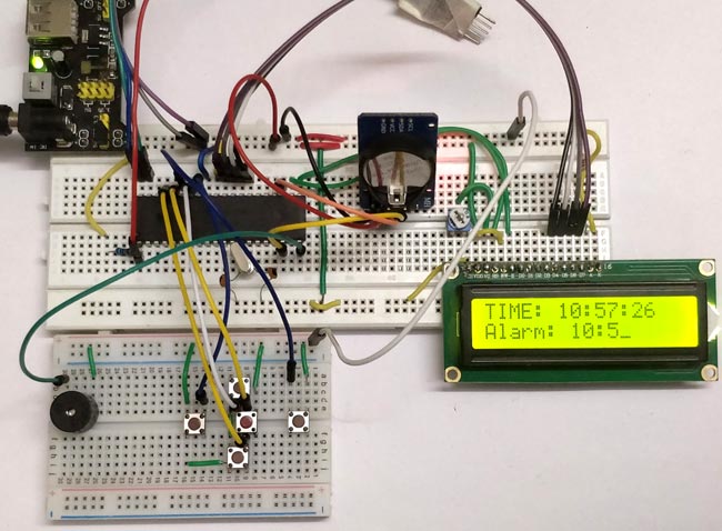
Build the circuit on the breadboard, get the code from the download link and compile it using MplabX and XC8 compiler. If you have downloaded the code from the ZIP file provided here, then you should have no problem compiling it since the header files are attached already.
After compiling upload the program to you hardware using the PicKit3 programmer. The connection to connect the pickit programmer to PIC IC is also shown in the circuit diagram. After the program is uploaded you should see the intro screen and then the time being displayed you can then use the push buttons to set the alarm time. My hardware set-up when powered looks like this below.

#pragma config FOSC = HS        // Oscillator Selection bits (HS oscillator)

#pragma config WDTE = OFF       // Watchdog Timer Enable bit (WDT disabled)

#pragma config PWRTE = ON       // Power-up Timer Enable bit (PWRT enabled)

#pragma config BOREN = ON       // Brown-out Reset Enable bit (BOR enabled)

#pragma config LVP = OFF        // Low-Voltage (Single-Supply) In-Circuit Serial Programming Enable bit (RB3 is digital I/O, HV on MCLR must be used for programming)

#pragma config CPD = OFF        // Data EEPROM Memory Code Protection bit (Data EEPROM code protection off)

#pragma config WRT = OFF        // Flash Program Memory Write Enable bits (Write protection off; all program memory may be written to by EECON control)

#pragma config CP = OFF         // Flash Program Memory Code Protection bit (Code protection off)


#define _XTAL_FREQ 20000000 //We are running on 20MHz crystal


//Define the LCD pins

#define RS RD2 //Reset pin of LCD

#define EN RD3 //Enable pin of LCD

#define D4 RD4 //Data bit 0 of LCD

#define D5 RD5 //Data bit 1 of LCD

#define D6 RD6 //Data bit 2 of LCD

#define D7 RD7 //Data bit 3 of LCD


//Define Buttons

#define MB RB1 //The middle button

#define LB RB0 //Left button

#define RB RB2 //Right button

#define UB RB3 //Upper Button

#define BB RB4 //Bottom button


//Define Buzz

#define BUZZ RD1 //Buzzer is connected to RD1


/*Set the current value of date and time below*/

int sec = 00;

int min = 55;

int hour = 10;

int date = 06;

int month = 05;

int year = 18;

/*Time and Date Set*/


/*Vars for Alarm clock*/

char set_alarm = 0;

char trigger_alarm = 0;

char pos = 8;

char jump = 0;


char alarm_h0 = 0;

char alarm_h1 = 0;

char alarm_m0 = 0;

char alarm_m1 = 0;

int alarm_val[4] = {0, 0, 0, 0};

/*End of var declaration*/


#include <xc.h>

#include "lcd.h" //Header for using LCD module

#include "PIC16F877a_I2C.h" // Header for using I2C protocal

#include "PIC16F877a_DS3231.h" //Header for using DS3231 RTC module


int main() {


    TRISD = 0x00; //Make Port D pins as outptu for LCD interfacing

    TRISB = 0xFF; //Switchs are declared as input pins

    OPTION_REG = 0b00000000; //Enable pull up Resistor on port B for switchs

    BUZZ = 0; //Turn of buzzer


    Lcd_Start(); // Initialize LCD module


    I2C_Initialize(100); //Initialize I2C Master with 100KHz clock


    //Remove the below line once time and date is set for the first time.

    Set_Time_Date(); //set time and date on the RTC module


    //Give an intro message on the LCD

         Lcd_Clear();

         Lcd_Set_Cursor(1,1);

         Lcd_Print_String("Alarm Clock");

         Lcd_Set_Cursor(2,1);

         Lcd_Print_String(" -Circuit Digest");

         __delay_ms(1500);


    while (1) {


        Update_Current_Date_Time(); //Read the current date and time from RTC module


        //Split the into char to display on lcd

        char sec_0 = sec % 10;

        char sec_1 = (sec / 10);

        char min_0 = min % 10;

        char min_1 = min / 10;

        char hour_0 = hour % 10;

        char hour_1 = hour / 10;


        //Display the Current Time on the LCD screen

        Lcd_Clear();

        Lcd_Set_Cursor(1, 1);

        Lcd_Print_String("TIME: ");

        Lcd_Print_Char(hour_1 + '0');

        Lcd_Print_Char(hour_0 + '0');

        Lcd_Print_Char(':');

        Lcd_Print_Char(min_1 + '0');

        Lcd_Print_Char(min_0 + '0');

        Lcd_Print_Char(':');

        Lcd_Print_Char(sec_1 + '0');

        Lcd_Print_Char(sec_0 + '0');


        //Display the Date on the LCD screen

        Lcd_Set_Cursor(2, 1);

        Lcd_Print_String("Alarm: ");

        Lcd_Print_Char(alarm_val[0] + '0');

        Lcd_Print_Char(alarm_val[1] + '0');

        Lcd_Print_Char(':');

        Lcd_Print_Char(alarm_val[2] + '0');

        Lcd_Print_Char(alarm_val[3] + '0');


        __delay_ms(50);


        //Use middle button to check if alarm has to be set

        if (MB == 0 && set_alarm == 0) { //If middle button is pressed and alarm is not turned on

            while (!MB); //Wait till button is released

            set_alarm = 1; //start setting alarm value

        }

        if (MB == 0 && set_alarm == 1) { //If middle button is pressed and alarm is not turned off

            while (!MB); //Wait till button is released

            set_alarm = 0; //stop setting alarm value

        }


        //If alarm has to be navigate through each digit

        if (set_alarm == 1) {

            if (LB == 0) { //If left button is pressed

                while (!LB); //Wait till button is released

                pos--; //Then move the cursor to left

            }

            if (RB == 0) { //If right button is pressed

                while (!RB); //Wait till button is released

                pos++; //Move cursor to right

            }


            if (pos >= 10) //eliminate ":" symbol if cursor reaches there

            {

                jump = 1; //Jump over the ":" symbol

            } else

                jump = 0; //get back to normal movement


            if (UB == 0) { //If upper button is pressed

                while (!UB); //Wait till button is released

                alarm_val[(pos - 8)]++; //Increase that particular char value

            }

            if (BB == 0) { //If lower button is pressed

                while (!UB); //Wait till button is released

                alarm_val[(pos - 8)]--; //Decrease that particular char value

            }


            Lcd_Set_Cursor(2, pos + jump);

            Lcd_Print_Char(95); //Display "_" to indicate cursor position

        }


        //IF alarm is set Check if the set value is equal to current value

        if (set_alarm == 0 && alarm_val[0] == hour_1 && alarm_val[1] == hour_0 && alarm_val[2] == min_1 && alarm_val[3] == min_0)

            trigger_alarm = 1; //Turn on trigger if value match


        if (trigger_alarm) { //If alarm is triggered

            //Beep the buzzer

            BUZZ = 1;

            __delay_ms(500);

            BUZZ = 0;

            __delay_ms(500);

        }


        __delay_ms(200);//Update interval


    }


    return 0;

}

How to make an alarm clock with pic microcontroller
- Comments(0)
- Likes(0)
- 0 USER VOTES
- YOUR VOTE 0.00 0.00
- 1
- 2
- 3
- 4
- 5
- 6
- 7
- 8
- 9
- 10
- 1
- 2
- 3
- 4
- 5
- 6
- 7
- 8
- 9
- 10
- 1
- 2
- 3
- 4
- 5
- 6
- 7
- 8
- 9
- 10
- 1
- 2
- 3
- 4
- 5
- 6
- 7
- 8
- 9
- 10
 More by electronicguru0007
-
 How to make an alarm clock with pic microcontroller
he five push buttons will act as an input for setting the alarm for the required time. So one end of...
-
 How to make RMS to DC Converter using IC AD736
A True-RMS or TRMS is a type of converter which converts RMS value to equivalent DC value. Here in t...
-
 STM32 SPI Communcation and Data Sent
SPI in STM32F103C8Comparing SPI bus in Arduino & STM32F103C8 Blue Pill board, STM32 has 2 SPI bu...
-
 How to Communicate Arduinos via RS-485
What project will you develop?The project consists of 3 Arduino's. We have an Arduino UNO, a Nano, a...
-
 PIC16F877A Temperature and Humidity Measurement Board
Temperature and Humidity measurement is often useful in many applications like Home Automation, Envi...
-
 Diy Buck Converter
n the field of DC-DC Converters, A single-ended primary-inductor converter or SEPIC converter is a t...
-
 Iot AC Current Measuring System
Smart power monitoring is getting increasingly popular to improve energy efficiency in medium/small ...
-
 ESP32 Weather Station
In this project, we will learn how to create a weather station, which will display reading from a BM...
-
 NRF Data Transfer Via 2 Boards
There are various wireless communication technologies used in building IoT applications and RF (Radi...
-
 Iot patient monitoring system
When we are talking about major vital signs of a human body, there are four major parameters that we...
-
 Setting up zigbee communication with nodemcu and arduino
Zigbee is a popular wireless communication protocol used to transfer a small amount of data with ver...
-
 Ac Dimmer Remote PCB
The brightness can be controlled using the IR remote of TV, DVD, etc. Dimming Control system using M...
-
 Esp32 Home Automation
There are relay modules whose electromagnet can be powered by 5V and with 3.3V. Both can be used wit...
-
 Lora Communication With Network
This was a very simple project and can come in handy for various applications. But what it can't do ...
-
 GPS Module Based Tracking Device Pcb
ESP32 GPS vehicle tracker using NEO 6M GPS module and Arduino IDE. With the help of this GPS tracker...
-
 Traffic Management for Emergency Vehicles using AT89S52 Microcontroller
These days’ traffic congestion is the biggest problem of densely populated cities. The project focus...
-
 Diy Multimeter Pcb
This is a project based on Arduino board which can measureresistance, diode, continuity[H1] , voltag...
-
 Live Instagram Followers Pcb
ESP8266 is capable of functioning reliably in industrial environments, with an operating temperature...
-
-
AEL-2011 Power Supply Module
515 0 2 -
AEL-2011 50W Power Amplifier
474 0 2 -
-
-
Custom Mechanical Keyboard
691 0 0 -
Tester for Touch Screen Digitizer without using microcontroller
322 2 2 -
Audio reactive glow LED wristband/bracelet with NFC / RFID-Tags
306 0 1 -
-
-


