|
Arduino Web Editor |
Setting up zigbee communication with nodemcu and arduino
Zigbee is a popular wireless communication protocol used to transfer a small amount of data with very low power. It is widely used in applications where data has to be shared among many nodes within personal space, and with the advent of the Internet of things (IoT), the application for Zigbee is fast growing. It is used in home automation, asset tracking, remote data collection, and much more. If you are already familiar with the architecture of Zigbee and Zigbee protocols, then you already know that wireless communication between two XBee modules can be done without any additional microcontrollers, but in practical application, these modules will always be interfaced with a microcontroller to read and send data. Let’s take that a step further and learn how to establish Zigbee communication using Arduino and NodeMCU boards.

Difference between Zigbee and XBee
It is important to clarify at the beginning itself that XBee is a module, a product, which supports many wireless communication protocols like ZigBee, Wi-Fi (Wi-Fly module), 802.15.4, 868 MHz modules, etc. Whereas, Zigbee is a standard protocol used to establish wireless networking (ZigBee communication). Often people use these two terms interchangeably but it shouldn’t be done so. To establish Zigbee communication, we need a receiver (endpoint). For this, an XBee module connected with Arduino/NodeMCU will do, and this will communicate wirelessly with another XBee module (coordinator) that sends data, will be connected to another Arduino board.
Hardware Requirements for Establishing Zigbee Communication
1 x Arduino Nano
1 x NodeMCU
2 x XBee Pro S2C modules
1 x XBee explorer board (to program XBee)
USB cables
LED (along with a 220-ohm resistor)
Push Button
Configuring XBee Modules using XCTU Software
Basically, the XBee module can be configured as Coordinator, Router, or End device. To make it work as we desire, first, we have to configure them using XCTU software. You can download and install the XCTU software using the given link.
Use USB to serial converter or an explorer board to connect the XBee module with a PC or Laptop. Connect the XBee module to the Explorer board and plugin using a USB cable. We will get into the details on how exactly we can use this software and configure the module, but before we do that, let's get our hardware ready.
Interfacing XBee with Arduino (Transmitting Side)
For this side of the connection, we’ve used Arduino Nano. Arduino Uno or NodeMCU boards could also be used. The complete circuit diagram to interface XBee with Arduino nano is shown below.
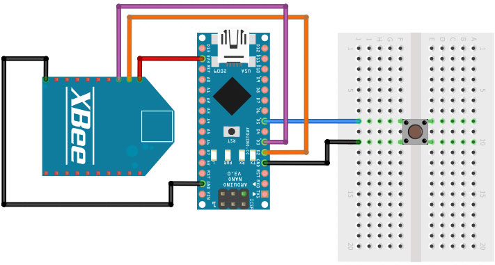
In the above Arduino XBee circuit diagram, we have used a push-button which, when pressed, will transmit data. For this, connect one end of the button to D5 of Arduino and the other end of the button to GND.
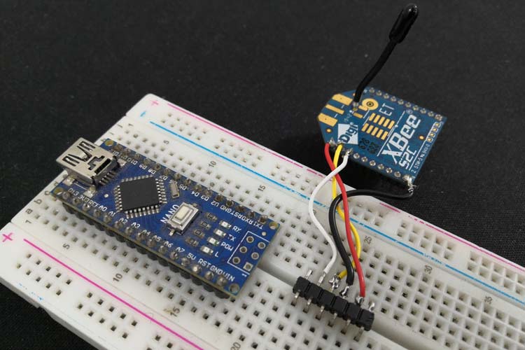
Connect VCC (pin 1) of XBee module to 3.3V of Arduino Nano and GND (pin 10) of XBee to GND of Arduino Nano. These two connections make up for powering the transmitting side XBee module. Connect Dout (pin 2) to D2 of Arduino Nano and Din (pin 3) to D3 of Arduino Nano. I used a breadboard to build this circuit and my hardware set-up with all the connections is shown below.
Interfacing XBee with NodeMCU (Receiving side)
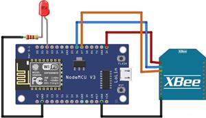
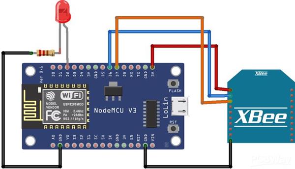
For this, we’ve used NodeMCU, but it has certain constraints. You can also use Arduino Nano or Arduino Uno for the purpose. The idea of using an Arduino to transmit data and NodeMCU to receive data is that it will have a more practical application like the Arduino can collect some sensor parameters and send it to the NodeMCU via ZigBee, then NodeMCU can process this data and share it or take any action via the Internet as required. The complete circuit diagram to interface XBee with NodeMCU is shown below.
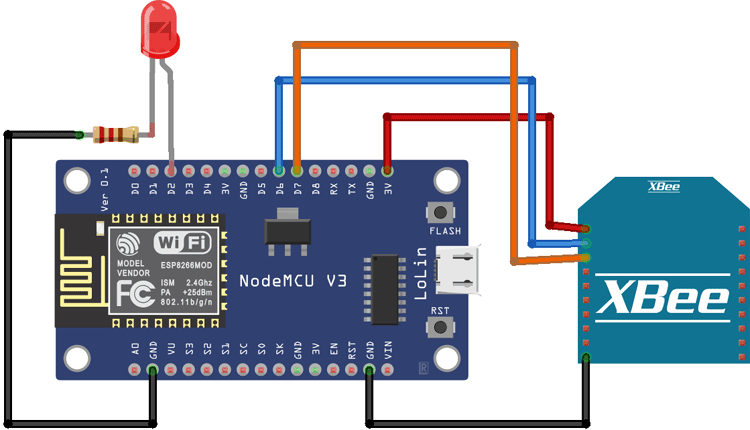
Connect Gnd(pin10) of XBee to GND of NodeMCU and Connect Vcc (Pin1) of XBee to 3.3V of NodeMCU. The above-mentioned two connections supply the power to the XBee module as well. Then connect Dout (pin2) of XBee to D6 pin of NodeMCU and Din (pin3) of XBee to D7 pin of NodeMCU for receiving data.
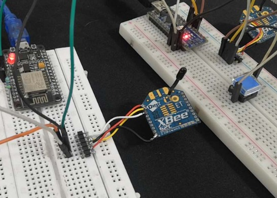
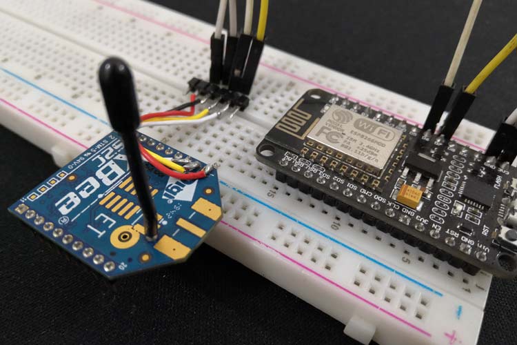
As an indication of whether the data is received or not, we’ve used LED. For this, connect LED anode to D2 of NodeMCU and LED cathode to GND through a 220ohm resistor of NodeMCU. Again, I used a breadboard to build this circuit and my hardware set-up with all the connections is shown below.
Downloading and Installing XCTU Software
To set up, configure and test your XBee devices. You need XCTU software. It’s an easy-to-use, free, multi-platform application for RF XBee modules. Download the XCTU software here and it’ll guide you to install it as well. After that, open the application and make sure your XBee module is connected properly. Check the COM port of the explorer board in the device manager.
Installing Firmware to XBee Modules
Firmware should be installed in both the XBee modules first, for that we’re using the XBee development board.
Step 1: Open XCTU software and click on “Discover boards”.

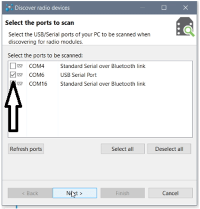
Step 2: Select the COM port to which the XBee module is connected and click on “Next”.
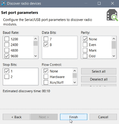
Step 3: Keep the default settings and click on “Finish”.
Step 4: Now, on the pop-up window, click on “Add Selected Devices”.
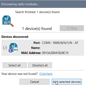
Step 5: Now, the XBee module will appear on the left side of the window. Click on it to update the user interface.

CODE: Receiver side #include<SoftwareSerial.h> int led = 2; int received = 0; int i; SoftwareSerial zigbee(13,12); void setup() { Serial.begin(9600); zigbee.begin(9600); pinMode(led, OUTPUT); } void loop() { if (zigbee.available() > 0) { received = zigbee.read(); if (received == '0'){ Serial.println("Turning off LED"); digitalWrite(led, LOW); } else if (received == '1'){ Serial.println("Turning on LED"); digitalWrite(led, HIGH); } } } CODE: Transmitter side #include "SoftwareSerial.h" SoftwareSerial XBee(2,3); int BUTTON = 5; boolean toggle = false; void setup() { Serial.begin(9600); pinMode(BUTTON, INPUT_PULLUP); XBee.begin(9600); } void loop() { if (digitalRead(BUTTON) == LOW && toggle) { Serial.println("Turn on LED"); toggle = false; XBee.write('1'); delay(1000); } else if (digitalRead(BUTTON) == LOW && !toggle) { Serial.println("Turn off LED"); toggle = true; XBee.write('0'); delay(1000); } }
Setting up zigbee communication with nodemcu and arduino

Raspberry Pi 5 7 Inch Touch Screen IPS 1024x600 HD LCD HDMI-compatible Display for RPI 4B 3B+ OPI 5 AIDA64 PC Secondary Screen(Without Speaker)
BUY NOW
ESP32-S3 4.3inch Capacitive Touch Display Development Board, 800×480, 5-point Touch, 32-bit LX7 Dual-core Processor
BUY NOW
Raspberry Pi 5 7 Inch Touch Screen IPS 1024x600 HD LCD HDMI-compatible Display for RPI 4B 3B+ OPI 5 AIDA64 PC Secondary Screen(Without Speaker)
BUY NOW- Comments(0)
- Likes(0)
 Log in to post comments.
- 0 USER VOTES
- YOUR VOTE 0.00 0.00
- 1
- 2
- 3
- 4
- 5
- 6
- 7
- 8
- 9
- 10
- 1
- 2
- 3
- 4
- 5
- 6
- 7
- 8
- 9
- 10
- 1
- 2
- 3
- 4
- 5
- 6
- 7
- 8
- 9
- 10
- 1
- 2
- 3
- 4
- 5
- 6
- 7
- 8
- 9
- 10
 More by electronicguru0007
-
 Esp32 Home Automation
There are relay modules whose electromagnet can be powered by 5V and with 3.3V. Both can be used wit...
-
 Lora Communication With Network
This was a very simple project and can come in handy for various applications. But what it can't do ...
-
 GPS Module Based Tracking Device Pcb
ESP32 GPS vehicle tracker using NEO 6M GPS module and Arduino IDE. With the help of this GPS tracker...
-
 Traffic Management for Emergency Vehicles using AT89S52 Microcontroller
These days’ traffic congestion is the biggest problem of densely populated cities. The project focus...
-
 Diy Multimeter Pcb
This is a project based on Arduino board which can measureresistance, diode, continuity[H1] , voltag...
-
 Live Instagram Followers Pcb
ESP8266 is capable of functioning reliably in industrial environments, with an operating temperature...
-
 How to make an alarm clock with pic microcontroller
he five push buttons will act as an input for setting the alarm for the required time. So one end of...
-
 How to make RMS to DC Converter using IC AD736
A True-RMS or TRMS is a type of converter which converts RMS value to equivalent DC value. Here in t...
-
 STM32 SPI Communcation and Data Sent
SPI in STM32F103C8Comparing SPI bus in Arduino & STM32F103C8 Blue Pill board, STM32 has 2 SPI bu...
-
 How to Communicate Arduinos via RS-485
What project will you develop?The project consists of 3 Arduino's. We have an Arduino UNO, a Nano, a...
-
 PIC16F877A Temperature and Humidity Measurement Board
Temperature and Humidity measurement is often useful in many applications like Home Automation, Envi...
-
 Diy Buck Converter
n the field of DC-DC Converters, A single-ended primary-inductor converter or SEPIC converter is a t...
-
 Iot AC Current Measuring System
Smart power monitoring is getting increasingly popular to improve energy efficiency in medium/small ...
-
 ESP32 Weather Station
In this project, we will learn how to create a weather station, which will display reading from a BM...
-
 NRF Data Transfer Via 2 Boards
There are various wireless communication technologies used in building IoT applications and RF (Radi...
-
 Iot patient monitoring system
When we are talking about major vital signs of a human body, there are four major parameters that we...
-
 Setting up zigbee communication with nodemcu and arduino
Zigbee is a popular wireless communication protocol used to transfer a small amount of data with ver...
-
 Ac Dimmer Remote PCB
The brightness can be controlled using the IR remote of TV, DVD, etc. Dimming Control system using M...
-
 Esp32 Home Automation
There are relay modules whose electromagnet can be powered by 5V and with 3.3V. Both can be used wit...
-
 Lora Communication With Network
This was a very simple project and can come in handy for various applications. But what it can't do ...
-
 GPS Module Based Tracking Device Pcb
ESP32 GPS vehicle tracker using NEO 6M GPS module and Arduino IDE. With the help of this GPS tracker...
-
 Traffic Management for Emergency Vehicles using AT89S52 Microcontroller
These days’ traffic congestion is the biggest problem of densely populated cities. The project focus...
-
 Diy Multimeter Pcb
This is a project based on Arduino board which can measureresistance, diode, continuity[H1] , voltag...
-
 Live Instagram Followers Pcb
ESP8266 is capable of functioning reliably in industrial environments, with an operating temperature...
-
 How to make an alarm clock with pic microcontroller
he five push buttons will act as an input for setting the alarm for the required time. So one end of...
-
 How to make RMS to DC Converter using IC AD736
A True-RMS or TRMS is a type of converter which converts RMS value to equivalent DC value. Here in t...
-
 STM32 SPI Communcation and Data Sent
SPI in STM32F103C8Comparing SPI bus in Arduino & STM32F103C8 Blue Pill board, STM32 has 2 SPI bu...
-
 How to Communicate Arduinos via RS-485
What project will you develop?The project consists of 3 Arduino's. We have an Arduino UNO, a Nano, a...
-
 PIC16F877A Temperature and Humidity Measurement Board
Temperature and Humidity measurement is often useful in many applications like Home Automation, Envi...
-
 Diy Buck Converter
n the field of DC-DC Converters, A single-ended primary-inductor converter or SEPIC converter is a t...
-
Commodore 64 1541-II Floppy Disk Drive C64 Power Supply Unit USB-C 5V 12V DIN connector 5.25
105 0 2 -
Easy to print simple stacking organizer with drawers
43 0 0 -
-
-
-
Modifying a Hotplate to a Reflow Solder Station
1071 1 6 -
MPL3115A2 Barometric Pressure, Altitude, and Temperature Sensor
590 0 1 -
-
Nintendo 64DD Replacement Shell
472 0 2 -
V2 Commodore AMIGA USB-C Power Sink Delivery High Efficiency Supply Triple Output 5V ±12V OLED display ATARI compatible shark 100W
1359 4 3


