
|
Arduino Web Editor |
PIC16F877A Temperature and Humidity Measurement Board
Temperature and Humidity measurement is often useful in many applications like Home Automation, Environment Monitoring, Weather station, etc. The most popularly used Temperature sensor next to LM35 is the DHT11, we have previously built many DHT11 Projects by interfacing it with Arduino, with Raspberry Pi and many other development boards. In this article, we will learn how to interface this DHT11 with PIC16F87A which is an 8-bit PIC Microcontroller. We will use this microcontroller to read the values of Temperature and Humidity using DHT11 and display it on an LCD display.

DHT11 – Specification and Working
The DHT11 sensor is available either in module form or in sensor form. In this tutorial we are using the sensor, the only difference between the both is that in module form the sensor has a filtering capacitor and a pull-up resistor attached to the output pin of the sensor. So if you are using the module you need not add them externally. The DHT11 in sensor form is shown below.
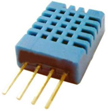
The DHT11 sensor comes with a blue or white color casing. Inside this casing, we have two important components that help us to sense the relative humidity and temperature. The first component is a pair of electrodes; the electrical resistance between these two electrodes is decided by a moisture-holding substrate. So the measured resistance is inversely proportional to the relative humidity of the environment. Higher the relative humidity lower will be the value of resistance and vice versa. Also, note that Relative humidity is different from actual humidity. Relative humidity measures the water content in the air relative to the temperature in the air.
The other component is a surface mounted NTC Thermistor. The term NTC stands for the Negative temperature coefficient, for the increase in temperature the value of resistance will decrease. The output of the sensor is factory calibrated and hence as a programmer we need not worry about calibrating the sensor. The output of the sensor given by 1-Wire communication, let's see the pin and connection diagram of this sensor.
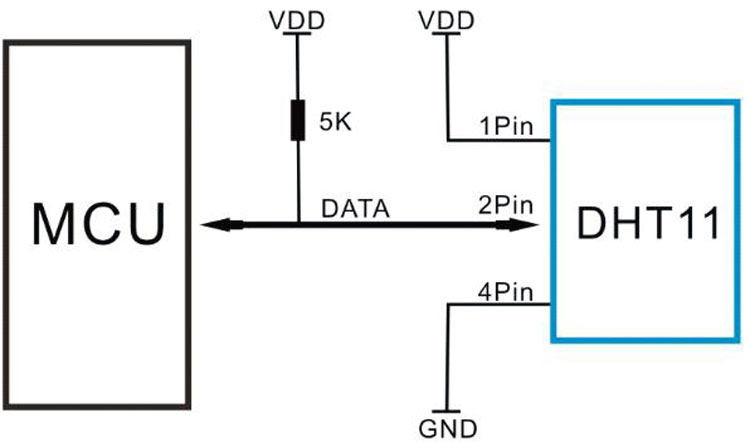
The product is in a 4pin single row package. 1st pin is connected across the VDD and the 4th pin is connected across the GND. The 2nd pin is the data pin, used for communication purposes. This data pin needs a pull-up resistor of 5k. However, others pull up resistors such as 4.7k to the 10k can also be used. The 3rd pin is not connected with anything. So it is ignored.
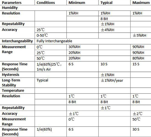
The datasheet provides technical specifications as well as interfacing information that can be seen in the below table-

The above table is showing Temperature and Humidity measurement range and accuracy. It can measure temperature from 0-50 degrees Celsius with an accuracy of +/- 2-degree Celsius and relative humidity from 20-90%RH with an accuracy of +/- 5%RH. The detail specification can be seen in the below table.
Communicating with DHT11 Sensor
As mentioned earlier, in order to read the data from DHT11 with PIC we have to use PIC one wire Communication protocol. The details on how to perform this can be understood from the interfacing diagram of DHT 11 which can be found in its datasheet, the same is given below.
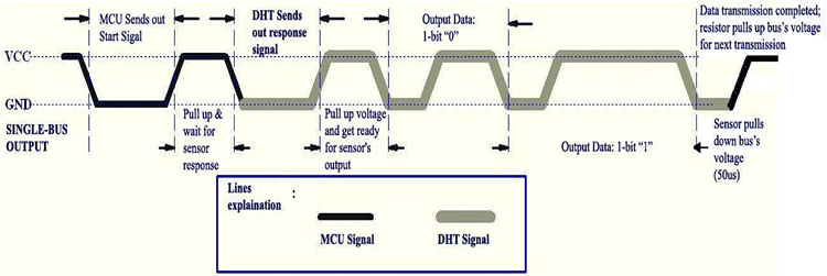
DHT11 needs a start signal from the MCU to start the communication. Therefore, every time the MCU needs to send a start signal to the DHT11 Sensor to request it to send the values of temperature and humidity. After completing the start signal, the DHT11 sends a response signal which includes the temperature and humidity information. The data communication is done by the single bus data communication protocol. The full data length is 40bit and the sensor sends higher data bit first.
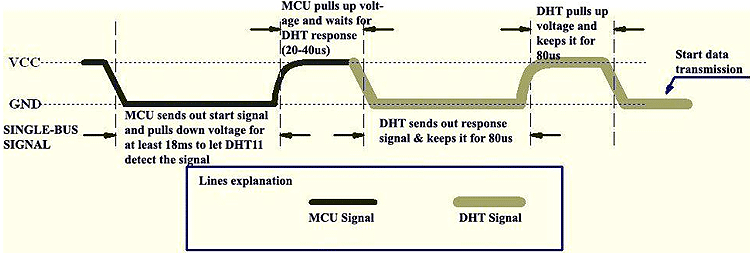
Due to the pull-up resistor, the data line always remains at the VCC level during idle mode. The MCU needs to pull down this voltage high to low for a minimum span of 18ms. During this time, the DHT11 sensor detects the start signal and the microcontroller makes the data line high for 20-40us. This 20-40us time is called a waiting period where the DHT11 starts to the response. After this waiting period, DHT11 sends the data to the microcontroller unit.
DHT11 Sensor DATA Format
The data consists of decimal and integral parts combined together. The sensor follows the below data format –
8bit integral RH data + 8bit decimal RH data + 8bit integral T data + 8bit decimal T data + 8bit checksum.
One can verify the data by checking the checksum value with the received data. This can be done because, if everything is proper and if the sensor has transmitted proper data, then the checksum should be the sum of “8bit integral RH data+8bit decimal RHdata+8bit integral T data+8bit decimal T data”.
Required components
For this project, below things are required -
PIC microcontroller (8bit) programming setup.
Breadboard
5V 500mA power supply unit.
4.7k resistor 2pcs
1k resistor
PIC16F877A
20mHz crystal
33pF capacitor 2 pcs
16x2 character LCD
DHT11 sensor
Jumper wires
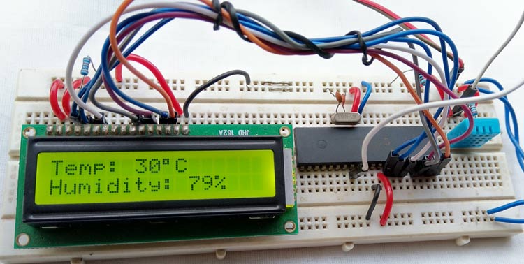
16x2 LCD to display the temperature and humidity values that we measure from DHT11. The LCD is interfaced in 4-wire mode and both the sensor and LCD are powered by a 5V external power supply. I have used a breadboard to make all the required connections and have used an external 5V adapter. You can also use this breadboard power supply board to power your board with 5V.

Once the circuit is ready, all we have to do is upload the code given at the bottom of this page and we can start reading the Temperature and Humidity like shown below. If you want to know how the code was written and how it works read further. Also you can find the complete working of this project in the video given at the bottom of this page.
DHT11 with PIC MPLABX Code explanation
The code was written using MPLABX IDE and compiled using the XC8 compiler both of which provided by Microchip itself and is free to download and use. Please refer to the basic tutorials to understand the basics of programming, only the three important functions which are required for communicating with the DHT11 sensor is discussed below. The functions are -
void dht11_init();

void find_response();

char read_dht11();

The first function is used for the start signal with dht11. As discussed before, every communication with DHT11 starts with a start signal, here the pin direction is changed at first to configure the data pin as output from the microcontroller. Then the data line is pulled low and keeps waiting for the 18mS. After that again the line is made high by the microcontroller and keeps waiting for up to 30us. After that waiting time, the data pin set as input to the microcontroller to receive the data.

void dht11_init(){

DHT11_Data_Pin_Direction= 0; //Configure RD0 as output

DHT11_Data_Pin = 0; //RD0 sends 0 to the sensor

__delay_ms(18);

DHT11_Data_Pin = 1; //RD0 sends 1 to the sensor

__delay_us(30);

DHT11_Data_Pin_Direction = 1; //Configure RD0 as input

}

The next function is used for setting up a check bit depending on the data pin status. It is used to detect the response from DHT11 sensor.

void find_response(){

Check_bit = 0;

__delay_us(40);

if (DHT11_Data_Pin == 0){

__delay_us(80);

if (DHT11_Data_Pin == 1){

Check_bit = 1;

}

__delay_us(50);}

}


Finally the dht11 read function; here the data is read into an 8-bit format where the data is returned using bit shift operation depending on the data pin status.

char read_dht11(){

char data, for_count;

for(for_count = 0; for_count < 8; for_count++){

while(!DHT11_Data_Pin);

__delay_us(30);

if(DHT11_Data_Pin == 0){

data&= ~(1<<(7 - for_count)); //Clear bit (7-b)

}

else{

data|= (1 << (7 - for_count)); //Set bit (7-b)

while(DHT11_Data_Pin);

}

}

return data;

}

?

After that, everything is done into the main function. First, the system initialization is done where the LCD is initialized and the LCD pins port direction is set to the output. The application is running inside the main function

void main() {

system_init();

while(1){

__delay_ms(800);

dht11_init();

find_response();

if(Check_bit == 1){

RH_byte_1 = read_dht11();

RH_byte_2 = read_dht11();

Temp_byte_1 = read_dht11();

Temp_byte_2 = read_dht11();

Summation = read_dht11();

if(Summation == ((RH_byte_1+RH_byte_2+Temp_byte_1+Temp_byte_2) & 0XFF)){

Humidity = Temp_byte_1;

RH = RH_byte_1;

lcd_com (0x80);

lcd_puts("Temp: ");

//lcd_puts(" ");

lcd_data(48 + ((Humidity / 10) % 10));

lcd_data(48 + (Humidity % 10));

lcd_data(0xDF);

lcd_puts("C ");

lcd_com (0xC0);

lcd_puts("Humidity: ");

//lcd_puts(" ");

lcd_data(48 + ((RH / 10) % 10));

lcd_data(48 + (RH % 10));

lcd_puts("% ");

}

else{

lcd_puts("Checksum error");

}

}

else {

clear_screen();

lcd_com (0x80);

lcd_puts("Error!!!");

lcd_com (0xC0);

lcd_puts("No Response.");

}

__delay_ms(1000);

}

}
PIC16F877A Temperature and Humidity Measurement Board
- Comments(0)
- Likes(0)
- 0 USER VOTES
- YOUR VOTE 0.00 0.00
- 1
- 2
- 3
- 4
- 5
- 6
- 7
- 8
- 9
- 10
- 1
- 2
- 3
- 4
- 5
- 6
- 7
- 8
- 9
- 10
- 1
- 2
- 3
- 4
- 5
- 6
- 7
- 8
- 9
- 10
- 1
- 2
- 3
- 4
- 5
- 6
- 7
- 8
- 9
- 10
 More by electronicguru0007
-
 How to make an alarm clock with pic microcontroller
he five push buttons will act as an input for setting the alarm for the required time. So one end of...
-
 How to make RMS to DC Converter using IC AD736
A True-RMS or TRMS is a type of converter which converts RMS value to equivalent DC value. Here in t...
-
 STM32 SPI Communcation and Data Sent
SPI in STM32F103C8Comparing SPI bus in Arduino & STM32F103C8 Blue Pill board, STM32 has 2 SPI bu...
-
 How to Communicate Arduinos via RS-485
What project will you develop?The project consists of 3 Arduino's. We have an Arduino UNO, a Nano, a...
-
 PIC16F877A Temperature and Humidity Measurement Board
Temperature and Humidity measurement is often useful in many applications like Home Automation, Envi...
-
 Diy Buck Converter
n the field of DC-DC Converters, A single-ended primary-inductor converter or SEPIC converter is a t...
-
 Iot AC Current Measuring System
Smart power monitoring is getting increasingly popular to improve energy efficiency in medium/small ...
-
 ESP32 Weather Station
In this project, we will learn how to create a weather station, which will display reading from a BM...
-
 NRF Data Transfer Via 2 Boards
There are various wireless communication technologies used in building IoT applications and RF (Radi...
-
 Iot patient monitoring system
When we are talking about major vital signs of a human body, there are four major parameters that we...
-
 Setting up zigbee communication with nodemcu and arduino
Zigbee is a popular wireless communication protocol used to transfer a small amount of data with ver...
-
 Ac Dimmer Remote PCB
The brightness can be controlled using the IR remote of TV, DVD, etc. Dimming Control system using M...
-
 Esp32 Home Automation
There are relay modules whose electromagnet can be powered by 5V and with 3.3V. Both can be used wit...
-
 Lora Communication With Network
This was a very simple project and can come in handy for various applications. But what it can't do ...
-
 GPS Module Based Tracking Device Pcb
ESP32 GPS vehicle tracker using NEO 6M GPS module and Arduino IDE. With the help of this GPS tracker...
-
 Traffic Management for Emergency Vehicles using AT89S52 Microcontroller
These days’ traffic congestion is the biggest problem of densely populated cities. The project focus...
-
 Diy Multimeter Pcb
This is a project based on Arduino board which can measureresistance, diode, continuity[H1] , voltag...
-
 Live Instagram Followers Pcb
ESP8266 is capable of functioning reliably in industrial environments, with an operating temperature...
-
-
AEL-2011 Power Supply Module
545 0 2 -
AEL-2011 50W Power Amplifier
505 0 2 -
-
-
Custom Mechanical Keyboard
706 0 0 -
Tester for Touch Screen Digitizer without using microcontroller
337 2 2 -
Audio reactive glow LED wristband/bracelet with NFC / RFID-Tags
317 0 1 -
-
-


