
|
A000052Arduino
|
x 5 | |
|
|
ERJ8BWFR010VRS-Components『 』Digi-Key
|
x 1 | |

|
SFR25H0001003FR500Vishay Beyschlag/Draloric/BC Components
|
x 1 | |

|
3266X-1-203LFBourns Inc.
|
x 1 | |

|
Mini Breadboard |
x 1 |

|
Arduino Web Editor |
How to Communicate Arduinos via RS-485
What project will you develop?
The project consists of 3 Arduino's. We have an Arduino UNO, a Nano, and a MEGA. The Arduino UNO will control the other 2 and send commands to receive the reading of the analog signal from the potentiometer connected to each Arduino.
He will receive the signal and present it on the LCD screen.

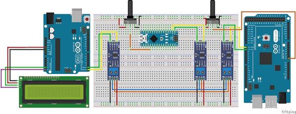
This communication will be developed through the use of RS-485 modules. See the circuit below.
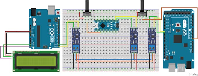
The MAX485 can transmit this data over a distance of 1200 m, in addition, it has high immunity to electromagnetic interference. This is one of the reasons why it is widely used by industrial devices, such as programmable logic controllers.
To make this communication we use the Arduino MAX485 module. This module will allow us to interconnect the devices and carry out our communication. See the photo of the module.
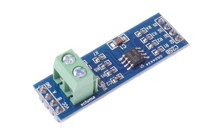
The board presents the complete circuit for you to transfer and receive data between the boards. The connecting pins are quite easy for you to learn.
Observe the figure and see that it is formed by 8 pins: DI, DE, RE,R0,VCC, A, B, and GND.
Shall we understand the function of each of them?
Pins DI and R0 are used to transmit data (DI - Data Input) and receive data (RO - Received Output). Connect the TX pin to the DI and the RX to the RO.
The configuration of the data transfer or reception mode is done through the DE and RE pins. The first thing you must do is connect the pins with a jumper.
Then, you must apply 5V to put the circuit in transfer mode and 0V to receive data. See the circuit in the figure and analyze the connection on the DE and RE pins.
In addition to these pins, we have VCC, A, B, and GND. The VCC and GND are used to supply the module circuit, while A and B will be responsible for transmitting information from one module to another with RS-485 voltage levels.
All pins of Letter A must connect to each other. This rule also applies to B.
Now you will learn the programming logic and the complete circuit for this project.
For this project, we'll use the JLCPCB Arduino Compatible printed circuit board presented below.
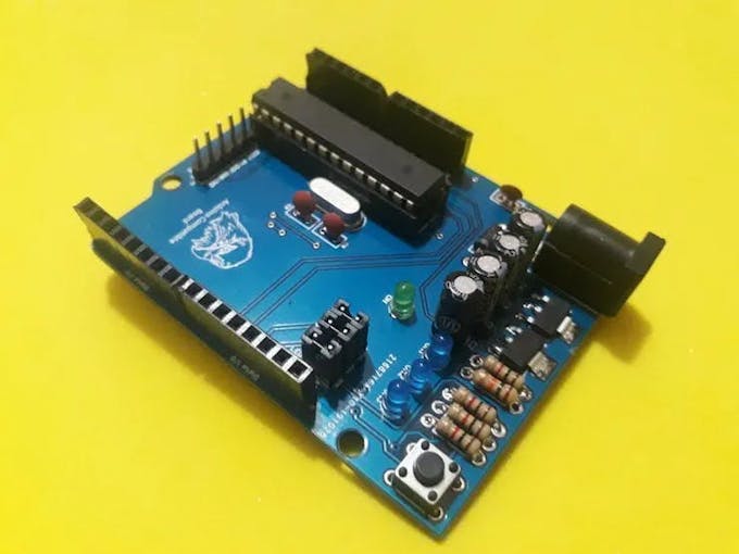
The project control logic
The logic is divided into two parts. We have the control logic of the Arduino Master and that of the slave Arduino's.
What is a master and slaves?
The master Arduino is responsible for the communication control, that is, only he can initiate communication with the slaves. In our project, Arduino UNO is the master of this communication.
Slave Arduino's only obey commands sent by the master. Arduino NANO and MEGA are Arduino's slaves.
See the figure below. We present 2 potentiometers. Each one is connected to each slave.
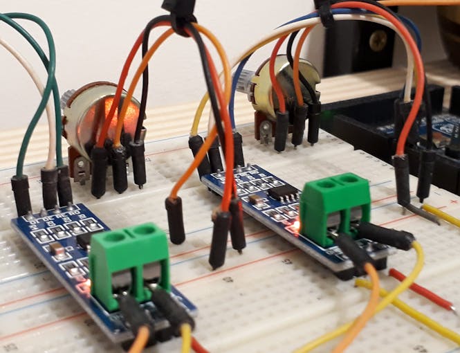
Now, see the code of the master Arduino.
#include <LiquidCrystal_I2C.h> //Biblioteca I2C do LCD 16x2
LiquidCrystal_I2C lcd(0x27,16,2); // Configurando o endereco do LCD 16x2 para 0x27
int value1 = 0, value2 = 0;
const int LED = 13;
const int Enable = 2;
void setup()
{
Serial.begin(9600);
Serial.setTimeout(250);
pinMode(LED, OUTPUT);
pinMode(Enable, OUTPUT);
digitalWrite(LED, LOW);
digitalWrite(Enable, HIGH);
lcd.init();
lcd.backlight();
}
void loop()
{
Serial.print("I");
Serial.print("1");
Serial.print("L");
Serial.print("F");
Serial.flush();
digitalWrite(Enable, LOW);
if(Serial.find("i"))
{
int slave1 = Serial.parseInt();
value1 = Serial.parseInt();
if(Serial.read() == 'f' && slave1 == 1)
{
lcd.setCursor(0,0);
lcd.print("Escravo 1: ");
lcd.setCursor(11,0);
lcd.print(value1);
}
}
digitalWrite(Enable, HIGH);
Serial.print("I");
Serial.print("2");
Serial.print("L");
Serial.print("F");
Serial.flush();
digitalWrite(Enable, LOW);
if(Serial.find("i"))
{
int slave2 = Serial.parseInt();
value2 = Serial.parseInt();
if(Serial.read() == 'f' && slave2 == 2)
{
lcd.setCursor(0,1);
lcd.print("Escravo 2: ");
lcd.setCursor(11,1);
lcd.print(value2);
}
}
digitalWrite(Enable, HIGH);
}
Initially we included libraries and declared all the variables of the project. See the code portion below.
#include <LiquidCrystal_I2C.h> //Biblioteca I2C do LCD 16x2
LiquidCrystal_I2C lcd(0x27,16,2); // Configurando o endereco do LCD 16x2 para 0x27
int value1 = 0, value2 = 0;
const int LED = 13;
const int Enable = 2;
In the setup function, we perform the configuration of the digital pins and set the enable pin to high logic level, to put the module in data transmission mode. See the code portion below.
void setup()
{
Serial.begin(9600);
Serial.setTimeout(250);
pinMode(LED, OUTPUT);
pinMode(Enable, OUTPUT);
digitalWrite(LED, LOW);
digitalWrite(Enable, HIGH);
lcd.init();
lcd.backlight();
}
After that, we have the main logic of the project.
void loop()
{
Serial.print("I");
Serial.print("1");
Serial.print("L");
Serial.print("F");
Serial.flush();
digitalWrite(Enable, LOW);
if(Serial.find("i"))
{
int slave1 = Serial.parseInt();
value1 = Serial.parseInt();
if(Serial.read() == 'f' && slave1 == 1)
{
lcd.setCursor(0,0);
lcd.print("Escravo 1: ");
lcd.setCursor(11,0);
lcd.print(value1);
}
}
digitalWrite(Enable, HIGH);
Serial.print("I");
Serial.print("2");
Serial.print("L");
Serial.print("F");
Serial.flush();
digitalWrite(Enable, LOW);
if(Serial.find("i"))
{
int slave2 = Serial.parseInt();
value2 = Serial.parseInt();
if(Serial.read() == 'f' && slave2 == 2)
{
lcd.setCursor(0,1);
lcd.print("Escravo 2: ");
lcd.setCursor(11,1);
lcd.print(value2);
}
}
digitalWrite(Enable, HIGH);
}
In the first lines of code, the Arduino master send a message to read the slave sensor 1.
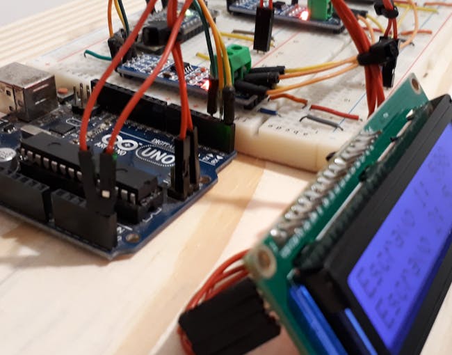
See the code block below.
Serial.print("I");
Serial.print("1");
Serial.print("L");
Serial.print("F");
Serial.flush();
Each character represents a different thing, see.
I represent the beginning of the communication;
1 represents the slave number;
L determines the sensor reading;
F represents the end of the message transmission.
After transmission, the communication mode pin is set to a low logic level. This serves to prepare the master to receive the information that will be sent by Arduino Slave 1.
digitalWrite(Enable, LOW);
Then the Arduino master waits to receive the character "i". This character signals the start of the response sent by slave 1.
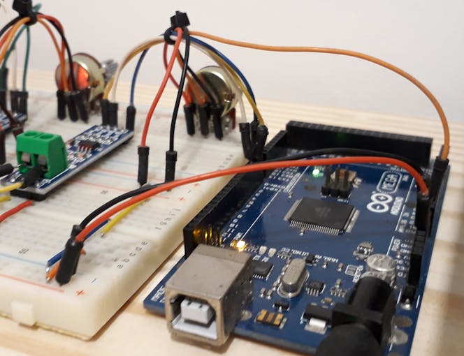
Slave 1 sending the analog value for master.
After that, it will receive slave number 1, the value of the analog signal, and the letter f, which signals the end of data transmission from slave 1. See the code below.
if(Serial.find("i"))
{
int slave1 = Serial.parseInt();
value1 = Serial.parseInt();
if(Serial.read() == 'f' && slave1 == 1)
{
lcd.setCursor(0,0);
lcd.print("Escravo 1: ");
lcd.setCursor(11,0);
lcd.print(value1);
}
}
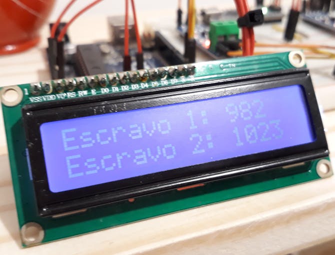
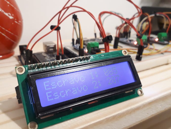
If the information received is from slave 1, the condition will be true and the Arduino will present the information received on line 1 of the LCD. See the image below.
The image below shows the result of the reading of slave 1 and slave 2 presented by the master.
After presenting the reading of slave 1, the code is repeated to read the analog signal on slave 2. See slave 2 below.
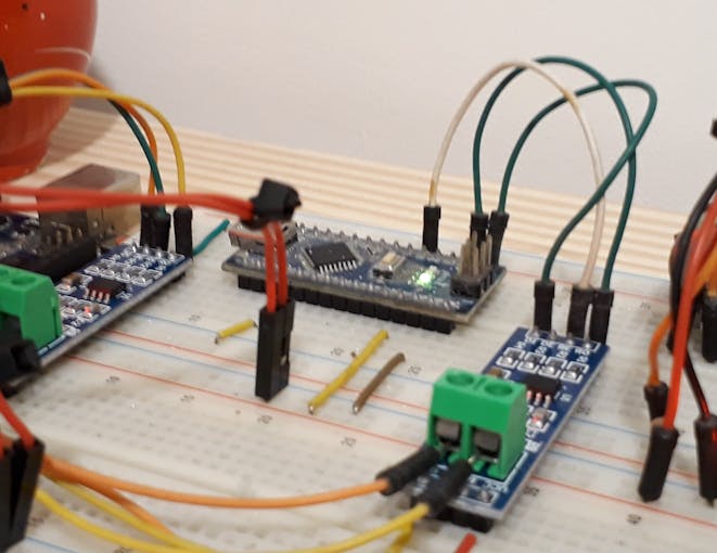
The code for reading the signal from slave 2 is the same as the code portion shown previously. See the code block below.
digitalWrite(Enable, HIGH);
Serial.print("I");
Serial.print("2");
Serial.print("L");
Serial.print("F");
Serial.flush();
digitalWrite(Enable, LOW);
if(Serial.find("i"))
{
int slave2 = Serial.parseInt();
value2 = Serial.parseInt();
if(Serial.read() == 'f' && slave2 == 2)
{
lcd.setCursor(0,1);
lcd.print("Escravo 2: ");
lcd.setCursor(11,1);
lcd.print(value2);
}
}
digitalWrite(Enable, HIGH);
The format of the message sent is the same. The only difference is the slave code. In this case, we use the value 2, because we want to receive the reading from slave 2. See the message.
Serial.print("I");
Serial.print("2");
Serial.print("L");
Serial.print("F");
Serial.flush();
After sending this message, the Arduino master waits for the response from slave 2 and shows the value on the LCD screen. The result can be seen below.

#include <LiquidCrystal_I2C.h> LiquidCrystal_I2C lcd(0x27,16,2); int value1 = 0, value2 = 0; const int LED = 13; const int Enable = 2; void setup() { Serial.begin(9600); Serial.setTimeout(250); pinMode(LED, OUTPUT); pinMode(Enable, OUTPUT); digitalWrite(LED, LOW); digitalWrite(Enable, HIGH); lcd.init(); lcd.backlight(); } void loop() { Serial.print("I"); Serial.print("1"); Serial.print("L"); Serial.print("F"); Serial.flush(); digitalWrite(Enable, LOW); if(Serial.find("i")) { int slave1 = Serial.parseInt(); value1 = Serial.parseInt(); if(Serial.read() == 'f' && slave1 == 1) { lcd.setCursor(0,0); lcd.print("Escravo 1: "); lcd.setCursor(11,0); lcd.print(value1); } } digitalWrite(Enable, HIGH); Serial.print("I"); Serial.print("2"); Serial.print("L"); Serial.print("F"); Serial.flush(); digitalWrite(Enable, LOW); if(Serial.find("i")) { int slave2 = Serial.parseInt(); value2 = Serial.parseInt(); if(Serial.read() == 'f' && slave2 == 2) { lcd.setCursor(0,1); lcd.print("Escravo 2: "); lcd.setCursor(11,1); lcd.print(value2); } } digitalWrite(Enable, HIGH); }
How to Communicate Arduinos via RS-485

Raspberry Pi 5 7 Inch Touch Screen IPS 1024x600 HD LCD HDMI-compatible Display for RPI 4B 3B+ OPI 5 AIDA64 PC Secondary Screen(Without Speaker)
BUY NOW
ESP32-S3 4.3inch Capacitive Touch Display Development Board, 800×480, 5-point Touch, 32-bit LX7 Dual-core Processor
BUY NOW
Raspberry Pi 5 7 Inch Touch Screen IPS 1024x600 HD LCD HDMI-compatible Display for RPI 4B 3B+ OPI 5 AIDA64 PC Secondary Screen(Without Speaker)
BUY NOW- Comments(0)
- Likes(2)
 Log in to post comments.
-
 Nenad Kezic
Aug 23,2023
-
 Dr. TRonik
Nov 19,2022
- 0 USER VOTES
- YOUR VOTE 0.00 0.00
- 1
- 2
- 3
- 4
- 5
- 6
- 7
- 8
- 9
- 10
- 1
- 2
- 3
- 4
- 5
- 6
- 7
- 8
- 9
- 10
- 1
- 2
- 3
- 4
- 5
- 6
- 7
- 8
- 9
- 10
- 1
- 2
- 3
- 4
- 5
- 6
- 7
- 8
- 9
- 10
 More by electronicguru0007
-
 Esp32 Home Automation
There are relay modules whose electromagnet can be powered by 5V and with 3.3V. Both can be used wit...
-
 Lora Communication With Network
This was a very simple project and can come in handy for various applications. But what it can't do ...
-
 GPS Module Based Tracking Device Pcb
ESP32 GPS vehicle tracker using NEO 6M GPS module and Arduino IDE. With the help of this GPS tracker...
-
 Traffic Management for Emergency Vehicles using AT89S52 Microcontroller
These days’ traffic congestion is the biggest problem of densely populated cities. The project focus...
-
 Diy Multimeter Pcb
This is a project based on Arduino board which can measureresistance, diode, continuity[H1] , voltag...
-
 Live Instagram Followers Pcb
ESP8266 is capable of functioning reliably in industrial environments, with an operating temperature...
-
 How to make an alarm clock with pic microcontroller
he five push buttons will act as an input for setting the alarm for the required time. So one end of...
-
 How to make RMS to DC Converter using IC AD736
A True-RMS or TRMS is a type of converter which converts RMS value to equivalent DC value. Here in t...
-
 STM32 SPI Communcation and Data Sent
SPI in STM32F103C8Comparing SPI bus in Arduino & STM32F103C8 Blue Pill board, STM32 has 2 SPI bu...
-
 How to Communicate Arduinos via RS-485
What project will you develop?The project consists of 3 Arduino's. We have an Arduino UNO, a Nano, a...
-
 PIC16F877A Temperature and Humidity Measurement Board
Temperature and Humidity measurement is often useful in many applications like Home Automation, Envi...
-
 Diy Buck Converter
n the field of DC-DC Converters, A single-ended primary-inductor converter or SEPIC converter is a t...
-
 Iot AC Current Measuring System
Smart power monitoring is getting increasingly popular to improve energy efficiency in medium/small ...
-
 ESP32 Weather Station
In this project, we will learn how to create a weather station, which will display reading from a BM...
-
 NRF Data Transfer Via 2 Boards
There are various wireless communication technologies used in building IoT applications and RF (Radi...
-
 Iot patient monitoring system
When we are talking about major vital signs of a human body, there are four major parameters that we...
-
 Setting up zigbee communication with nodemcu and arduino
Zigbee is a popular wireless communication protocol used to transfer a small amount of data with ver...
-
 Ac Dimmer Remote PCB
The brightness can be controlled using the IR remote of TV, DVD, etc. Dimming Control system using M...
-
 Esp32 Home Automation
There are relay modules whose electromagnet can be powered by 5V and with 3.3V. Both can be used wit...
-
 Lora Communication With Network
This was a very simple project and can come in handy for various applications. But what it can't do ...
-
 GPS Module Based Tracking Device Pcb
ESP32 GPS vehicle tracker using NEO 6M GPS module and Arduino IDE. With the help of this GPS tracker...
-
 Traffic Management for Emergency Vehicles using AT89S52 Microcontroller
These days’ traffic congestion is the biggest problem of densely populated cities. The project focus...
-
 Diy Multimeter Pcb
This is a project based on Arduino board which can measureresistance, diode, continuity[H1] , voltag...
-
 Live Instagram Followers Pcb
ESP8266 is capable of functioning reliably in industrial environments, with an operating temperature...
-
 How to make an alarm clock with pic microcontroller
he five push buttons will act as an input for setting the alarm for the required time. So one end of...
-
 How to make RMS to DC Converter using IC AD736
A True-RMS or TRMS is a type of converter which converts RMS value to equivalent DC value. Here in t...
-
 STM32 SPI Communcation and Data Sent
SPI in STM32F103C8Comparing SPI bus in Arduino & STM32F103C8 Blue Pill board, STM32 has 2 SPI bu...
-
 How to Communicate Arduinos via RS-485
What project will you develop?The project consists of 3 Arduino's. We have an Arduino UNO, a Nano, a...
-
 PIC16F877A Temperature and Humidity Measurement Board
Temperature and Humidity measurement is often useful in many applications like Home Automation, Envi...
-
 Diy Buck Converter
n the field of DC-DC Converters, A single-ended primary-inductor converter or SEPIC converter is a t...
-
-
Commodore 64 1541-II 1581 Floppy Disk Drive C64 Power Supply Unit USB-C 5V 12V DIN connector 5.25
314 1 3 -
Easy to print simple stacking organizer with drawers
112 0 0 -
-
-
-
-
-
-
Modifying a Hotplate to a Reflow Solder Station
1208 1 6 -
MPL3115A2 Barometric Pressure, Altitude, and Temperature Sensor
689 0 1 -


