
|
Arduino Web Editor |
Diy Buck Converter
n the field of DC-DC Converters, A single-ended primary-inductor converter or SEPIC converter is a type of converter that uses a boost type control topology to step up or step down the input voltage. After reading this, the first question that will come to your mind would be, is it like a glorified Classic Buck-Boost Converter? The answer is yes and no. A classic buck-boost converter consists of two inductors and two switches that increase the cost, so to reduce it, a much more complex topology known as the inverting buck-boost converter is used. We have discussed it in one of our previous articles. In an Inverting buck-boost converter, the output polarity of the inverting buck-boost converter is opposite to that of the input. A sepic converter addresses these issues by introducing a coupled inductor that reduces the overall cost and also takes less space in the actual circuit board.

So in this article, we are going to learn how to build, and test a simplified Sepic converter built on top of the popular XL6009 IC. We have previously used this XL6009 IC to Design a Mobile Power bank and an Adjustable Buck-Boost Regulator (3.3V to 12V), you can also check them out if you are interested.
Working of SEPIC Converter (Single-Ended Primary-Inductor Converter)
The schematic below is a basic schematic of a SEPIC converter and in this article, we are going to use this to explain the working principle.
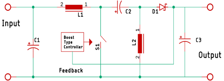
SEPIC converter is a buck-boost topology, unlike the classic buck-boost that is an inverting topology. A SEPIC converter is characterized by using two inductors, one is at the input and another one is connected to the ground and these two inductors are connected by a coupling capacitor, which effectively puts the L1 and L2 in parallel when a switching signal is applied.
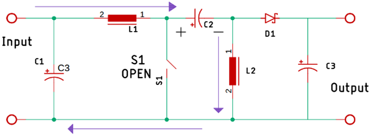
Now, to understand the working of the SEPIC converter we have modified the basic circuit and removed the controller from the picture. As you can see when the power is applied to the circuit at that brief moment the switch is open and the capacitor C2 starts charging through the inductor L1. Now as the controller IC turns on, it turns on the switch.
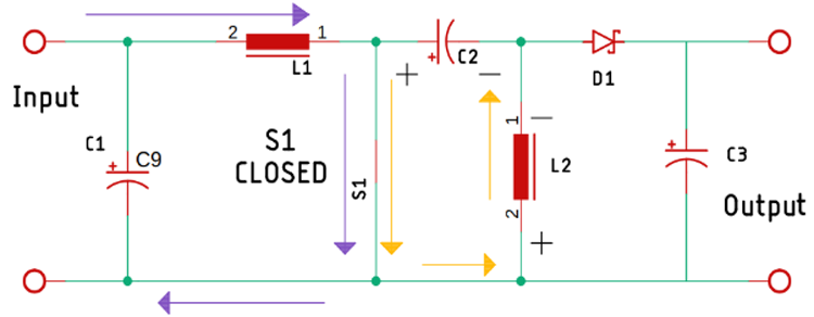
Now, as the switch is turned on, two things happen simultaneously, first the inductor L1 and L2 start charging simultaneously. When that happens, the switch gets opened because of the PWM pulse that is generated by the internal circuit of the XL6009 IC.
The working principle of this circuit is very simple. First, we have our input storage capacitor that is directly connected to the input VCC pin of the IC. Next, we have our coupling capacitor, a 47uH 4A coupled inductor is recommended on the example schematic that is taken from Fig 6 of the Xl6009 datasheet. The coupled inductor can be any type; it can be a coupled transformer or in my case, it is a toroidal bobbin that we have disordered out from an old non-working ATX power supply. The output diode is a MUR810 diode that is 8A and 100V. Next, we have our feedback circuit that consists of a 10K resistor and a 10K potentiometer. Finally, we have our output capacitors that store the output voltage. Once we are done with the soldering process, the board looks like the image shown below.

PCB for XL6009 Based SEPIC Converter
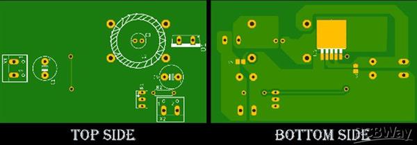
The PCB for our SEPIC Buck-Boost Converter circuit is designed on a single-sided board. I have used Eagle to design my PCB but you can use any PCB design software of your choice. The 2D image of the top and bottom of the PCB that is generated by Eagle is shown below.

As you can see on the very left of the PCB, we have our Input power connector and on the bottom right corner, we have our output connector. We have used a capacitor in the middle of the coupled inductor as it was very convenient to put it there, the capacitor C3 on the PCB is the capacitor C2 that we have shown in our basic schematic. The main driver of this SEPIC converter is the XL6009 IC, it’s on the bottom of the PCB . As it’s an SMD component, we had to place it on the bottom. We have used a thick ground plane to ensure sufficient current can flow through it.
Testing the XL6009 Based SEPIC Buck-Boost Converter Circuit
Note: While powering this circuit for the first time, do use a Constant Current Power Supply to limit the current or you can use a bunch of power resistors to limit the current. If you have made some mistakes while the soldering process, the XL6009 may burn out.

As you can see, the above test setup is used to test the circuit. An ATX PC, power supply is used to power the circuit which is why the input voltage stays at 12V. You can also see that the circuit is currently operating in boost mode so the output stays at 43.26V volts in this condition and I have attached a minimal load of 2.2K 1W resistor to the circuit and it was drawing around .02A of current.

The image above shows that this circuit can reach a minimum voltage of 2.5V at minimum load conditions.
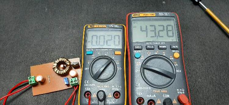
Since I only have two multimeters at my disposal, I have used the mecho 450B+ Multimeter to display the output voltage and I have used the MECHO 108B+ Multimeter to measure the output current.
Diy Buck Converter
- Comments(0)
- Likes(1)
-
 Engineer
Sep 01,2022
- 0 USER VOTES
- YOUR VOTE 0.00 0.00
- 1
- 2
- 3
- 4
- 5
- 6
- 7
- 8
- 9
- 10
- 1
- 2
- 3
- 4
- 5
- 6
- 7
- 8
- 9
- 10
- 1
- 2
- 3
- 4
- 5
- 6
- 7
- 8
- 9
- 10
- 1
- 2
- 3
- 4
- 5
- 6
- 7
- 8
- 9
- 10
 More by electronicguru0007
-
 How to make an alarm clock with pic microcontroller
he five push buttons will act as an input for setting the alarm for the required time. So one end of...
-
 How to make RMS to DC Converter using IC AD736
A True-RMS or TRMS is a type of converter which converts RMS value to equivalent DC value. Here in t...
-
 STM32 SPI Communcation and Data Sent
SPI in STM32F103C8Comparing SPI bus in Arduino & STM32F103C8 Blue Pill board, STM32 has 2 SPI bu...
-
 How to Communicate Arduinos via RS-485
What project will you develop?The project consists of 3 Arduino's. We have an Arduino UNO, a Nano, a...
-
 PIC16F877A Temperature and Humidity Measurement Board
Temperature and Humidity measurement is often useful in many applications like Home Automation, Envi...
-
 Diy Buck Converter
n the field of DC-DC Converters, A single-ended primary-inductor converter or SEPIC converter is a t...
-
 Iot AC Current Measuring System
Smart power monitoring is getting increasingly popular to improve energy efficiency in medium/small ...
-
 ESP32 Weather Station
In this project, we will learn how to create a weather station, which will display reading from a BM...
-
 NRF Data Transfer Via 2 Boards
There are various wireless communication technologies used in building IoT applications and RF (Radi...
-
 Iot patient monitoring system
When we are talking about major vital signs of a human body, there are four major parameters that we...
-
 Setting up zigbee communication with nodemcu and arduino
Zigbee is a popular wireless communication protocol used to transfer a small amount of data with ver...
-
 Ac Dimmer Remote PCB
The brightness can be controlled using the IR remote of TV, DVD, etc. Dimming Control system using M...
-
 Esp32 Home Automation
There are relay modules whose electromagnet can be powered by 5V and with 3.3V. Both can be used wit...
-
 Lora Communication With Network
This was a very simple project and can come in handy for various applications. But what it can't do ...
-
 GPS Module Based Tracking Device Pcb
ESP32 GPS vehicle tracker using NEO 6M GPS module and Arduino IDE. With the help of this GPS tracker...
-
 Traffic Management for Emergency Vehicles using AT89S52 Microcontroller
These days’ traffic congestion is the biggest problem of densely populated cities. The project focus...
-
 Diy Multimeter Pcb
This is a project based on Arduino board which can measureresistance, diode, continuity[H1] , voltag...
-
 Live Instagram Followers Pcb
ESP8266 is capable of functioning reliably in industrial environments, with an operating temperature...
-
-
mammoth-3D SLM Voron Toolhead – Manual Drill & Tap Edition
186 0 0 -
-
AEL-2011 Power Supply Module
713 0 2 -
AEL-2011 50W Power Amplifier
596 0 2 -
-
-
Custom Mechanical Keyboard
796 0 0 -
Tester for Touch Screen Digitizer without using microcontroller
418 2 2 -
Audio reactive glow LED wristband/bracelet with NFC / RFID-Tags
379 0 1 -
-


