
|
arduino IDEArduino
|
Heart Rate Monitor Pcb
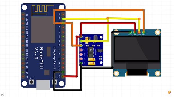
Hi, in this tutorial we gonna interface MAX30102: pulse oximetry and heart rate monitor module with Arduino UNO board, and then make a project for measuring BPM using this module + OLED display if needed (a Buzzer).
BPM are the "beats per minute" and they are around 65-75 while resting for a normal person, athletics may have lower than that, and the SpO2 is the Oxygen saturation level, and for a normal person it's above 95%.

The MAX30102 can be found in different modules, I have a WAVGAT version, it's not a problem as long as the IC is MAX30102.
The codes I used in the tutorial are pretty clear and they are just examples from the Sparkfun_MAX3010x library.
For the code I made for the OLED and Buzzer, it's a modified version of the "HeartRate" example, it asks you to put your finger on the sensor.

How does it work?
There is a pulse rate sensor module in our project which plays an important role in calculating the heartbeat rate. Hold the sensor between your fingers or you can also put your finger on it so that the sensor can take the readings. After it, the Arduino does all the processing and calculation and sends the final output signals to the OLED display. The OLED display is much better than other displays because it has more pixels than other ordinary display modules. Finally, you can see the BPM values on the display with a graphical representation of the values. The values keep updating continuously till you remove your finger from the sensor.

This sensor does nothing but measure heart rate of the heart, it can be found in any medical equipment that is used in measuring heart rate. It can be worn on the finger or on the earlobe.
Suitable for all projects that require heart rate data.
In fact today's purpose is this, measure heart rate with the XD-58C sensor.

Once you put your finger, remain calm for a while, until you start hearing the Buzzer's "Beeps" synchronized with your heart beats or the OLED animation is synchronized with it, and then you can read a correct BPM.
N.B: In the code I actually print the Average BPM, since it do the average of 4 BPMs it's more accurate just give it some time.
After a while you'll have a good BPM reading and a synchronized animation/"Beeps"
Make Bitmaps for the OLED
The heart (small) you see is a bitmap picture, and everytime the sensor detects a heart beat we switch to another heart (big) bitmap picture for a while and it gives the impression of a heart beats alongside with a beep from the buzzer.
Here are the two bitmaps in the code that we call later on the code
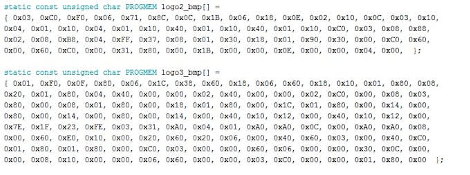
I called them logo2_bmp and logo3_bmp I don't know why

To make these, Look for a picture (black with white background) for wathever you want to see in the screen just don't forget about the size, the one I'm using is 128x32 px and the pictures are smaller than that (32x32 px) and (24x21 px)

Make sure the little pictures have Monochrome Bitmap format
Download LCD Assistant and open it (few steps below)
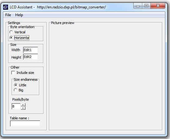
Open the Assistant Try these operations in both Vertical and Horizontal until it's right
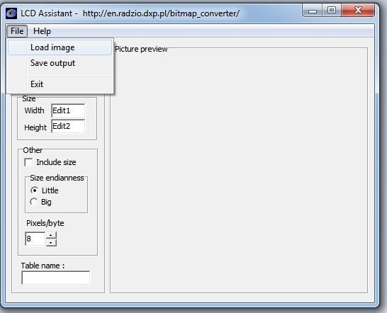
Look for you image
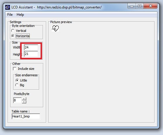
Note the Width and Height of the image
Give the file a name and path then save it
Open the file with note pad or anything similar
And here are your "numbers"

Copy this and put it in your code, add PROGMEM to put it in the Arduino Flash and save some space
And here's how I called it in the code
display.drawBitmap(5, 5, logo2_bmp, 24, 21, WHITE);

Which means
display.drawBitmap(Starting x pos, Starting y pos, Bitmap name, Width, Height, Color);
And as you can see in the code one is called when a finger is detected and the other one if a heart beat is detected.
And here you go make what you want.


#include <Adafruit_SSD1306.h>
#define OLED_Address 0x3C // 0x3C device address of I2C OLED. Few other OLED has 0x3D
Adafruit_SSD1306 oled(128, 64); // create our screen object setting resolution to 128x64

int a=0;
int lasta=0;
int lastb=0;
int LastTime=0;
int ThisTime;
bool BPMTiming=false;
bool BeatComplete=false;
int BPM=0;
#define UpperThreshold 560
#define LowerThreshold 530

void setup() {
oled.begin(SSD1306_SWITCHCAPVCC, OLED_Address);
oled.clearDisplay();
oled.setTextSize(2);
}

void loop()
{
if(a>127)
{
oled.clearDisplay();
a=0;
lasta=a;
}

ThisTime=millis();
int value=analogRead(0);
oled.setTextColor(WHITE);
int b=60-(value/16);
oled.writeLine(lasta,lastb,a,b,WHITE);
lastb=b;
lasta=a;

if(value>UpperThreshold)
{
if(BeatComplete)
{
BPM=ThisTime-LastTime;
BPM=int(60/(float(BPM)/1000));
BPMTiming=false;
BeatComplete=false;
tone(8,1000,250);
}
if(BPMTiming==false)
{
LastTime=millis();
BPMTiming=true;
}
}
if((value<LowerThreshold)&(BPMTiming))
BeatComplete=true;

oled.writeFillRect(0,50,128,16,BLACK);
oled.setCursor(0,50);
oled.print("BPM:");
oled.print(BPM);

oled.display();
a++;
}
Heart Rate Monitor Pcb
- Comments(0)
- Likes(1)
-
 (DIY) C64iSTANBUL
Jul 26,2022
- 0 USER VOTES
- YOUR VOTE 0.00 0.00
- 1
- 2
- 3
- 4
- 5
- 6
- 7
- 8
- 9
- 10
- 1
- 2
- 3
- 4
- 5
- 6
- 7
- 8
- 9
- 10
- 1
- 2
- 3
- 4
- 5
- 6
- 7
- 8
- 9
- 10
- 1
- 2
- 3
- 4
- 5
- 6
- 7
- 8
- 9
- 10
 More by electronicguru0007
-
 How to make an alarm clock with pic microcontroller
he five push buttons will act as an input for setting the alarm for the required time. So one end of...
-
 How to make RMS to DC Converter using IC AD736
A True-RMS or TRMS is a type of converter which converts RMS value to equivalent DC value. Here in t...
-
 STM32 SPI Communcation and Data Sent
SPI in STM32F103C8Comparing SPI bus in Arduino & STM32F103C8 Blue Pill board, STM32 has 2 SPI bu...
-
 How to Communicate Arduinos via RS-485
What project will you develop?The project consists of 3 Arduino's. We have an Arduino UNO, a Nano, a...
-
 PIC16F877A Temperature and Humidity Measurement Board
Temperature and Humidity measurement is often useful in many applications like Home Automation, Envi...
-
 Diy Buck Converter
n the field of DC-DC Converters, A single-ended primary-inductor converter or SEPIC converter is a t...
-
 Iot AC Current Measuring System
Smart power monitoring is getting increasingly popular to improve energy efficiency in medium/small ...
-
 ESP32 Weather Station
In this project, we will learn how to create a weather station, which will display reading from a BM...
-
 NRF Data Transfer Via 2 Boards
There are various wireless communication technologies used in building IoT applications and RF (Radi...
-
 Iot patient monitoring system
When we are talking about major vital signs of a human body, there are four major parameters that we...
-
 Setting up zigbee communication with nodemcu and arduino
Zigbee is a popular wireless communication protocol used to transfer a small amount of data with ver...
-
 Ac Dimmer Remote PCB
The brightness can be controlled using the IR remote of TV, DVD, etc. Dimming Control system using M...
-
 Esp32 Home Automation
There are relay modules whose electromagnet can be powered by 5V and with 3.3V. Both can be used wit...
-
 Lora Communication With Network
This was a very simple project and can come in handy for various applications. But what it can't do ...
-
 GPS Module Based Tracking Device Pcb
ESP32 GPS vehicle tracker using NEO 6M GPS module and Arduino IDE. With the help of this GPS tracker...
-
 Traffic Management for Emergency Vehicles using AT89S52 Microcontroller
These days’ traffic congestion is the biggest problem of densely populated cities. The project focus...
-
 Diy Multimeter Pcb
This is a project based on Arduino board which can measureresistance, diode, continuity[H1] , voltag...
-
 Live Instagram Followers Pcb
ESP8266 is capable of functioning reliably in industrial environments, with an operating temperature...
-
MPL3115A2 Barometric Pressure, Altitude, and Temperature Sensor
39 0 0 -
-
Nintendo 64DD Replacement Shell
142 0 1 -
V2 Commodore AMIGA USB-C Power Sink Delivery High Efficiency Supply Triple Output 5V ±12V OLED display ATARI compatible shark 100W
253 4 1 -
How to measure weight with Load Cell and HX711
371 0 3 -
-
Instrumentation Input, high impedance with 16 bit 1MSPS ADC for SPI
503 0 0


