|
arduino IDEArduino
|
Ac Dimmer Pcb
In our household, most of the appliances are powered from the AC supply such as Lights, TVs, and Fans, etc. We can turn ON/OFF them digitally if needed, using Arduino and Relays by building a Home automation setup. But what if we need to control the power of those devices for example to dim the AC Lamp or to Control the speed of the Fan. In that case, we have to use phase control technique and static switches like TRIAC to control the phase of AC supply voltage.
So in this tutorial, we will learn about an AC lamp dimmer using Arduino and TRIAC. Here a TRIAC is used to switch the AC lamp, as this is a Power electronic fast switching device which is the best suited for these applications. Let’s follow the complete article for the hardware details and programming of this project. Also, check our previous tutorials on Light Dimming:

Zero Crossing Detection Technique
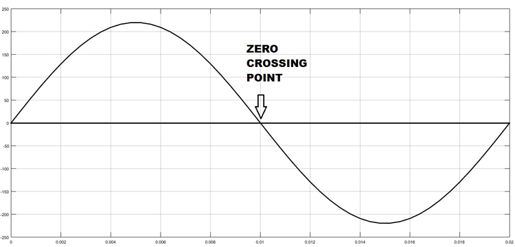
To control the AC voltage, the first thing we have to do is, to detect the zero crossing of the AC signal. In India, the frequency of AC signal is 50 HZ and as it is alternating in nature. Hence, every time the signal comes to Zero point, we have to detect that point and after that trigger the TRIAC as per the power requirement. The Zero crossing point of an AC signal is shown below:
TRIAC Working

TRIAC is a three-terminal AC switch which can be triggered by a low energy signal at its gate terminal. In SCRs, it conducts in only one direction, but in the case of TRIAC the power can be controlled at both directions. Here we are using a BT136 TRIAC for AC Lamp dimming purpose.
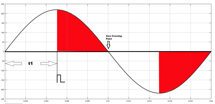
As shown in the figure above, the TRIAC is triggered at a firing angle of 90 degrees by applying a small gate pulse signal to it. The time “t1” is the delay time which we have to give as per our dimming requirement. For example, in this case as the firing angle is 90 percent, hence the power output will also be halved and hence the lamp will also glow with half intensity.
We know that the frequency of AC signal is 50 Hz here. So the time period will be 1/f, which will be 20ms., so for a half cycle, this will be 10ms or 10,000 microseconds. Hence for controlling the power of our AC lamp, the range of “t1” can be varied from 0-10000 microseconds. Learn more about Triac and its working here.
Optocoupler
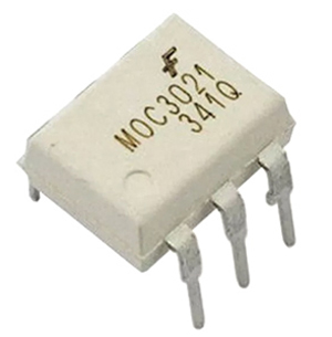
Optocoupler is also known as Optoisolator. It is used to maintain isolation between two electrical circuits like DC and AC signals. Basically, it consists of an LED that emits infrared light and the photosensor which detects it. Here we are used a MOC3021 optocoupler to control the AC lamp from microcontroller signals which is a DC signal. We previously used the same MOC3021 optocoupler in TRIAC dimmer circuit. Also learn more about Optocouplers and its types by following the link.
Circuit Diagram:
Circuit diagram for AC Light Dimmer is given below:

Programming Arduino for AC Light Dimmer:
After successful completion of hardware setup, now its time to program the Arduino. The complete program with a demo video is given at the end. Here we have explained the code stepwise for better understating.
In the first step, declare all the global variables, which are going to use throughout the code. Here the TRIAC is connected to pin 4 of Arduino. Then the dim_val is declared to store the value of the dimming step which we will use in the program.
int LAMP = 4;
int dim_val=0;
Next, inside setup function declare the LAMP pin as output and next configure an interrupt to detect the zero crossing. Here we have used a function called attachInterrupt, which will configure digital Pin 2 of Arduino as external interrupt and it will call the function named zero_cross, when it detects any interrupts at its pin.
void setup()
{
pinMode(LAMP, OUTPUT);
attachInterrupt(digitalPinToInterrupt(2), zero_cross, CHANGE);
}
Inside infinite loop, read the analog value from potentiometer which is connected at A0. Then map it to a value range of (10-49). To find out this we have to do a small calculation. Earlier I have told that, each half cycle is equivalent to 10,000 microseconds. So, let we need to control the dimming in 50 steps (which is an arbitrary value. You can also change it). I have taken the minimum step as 10, not Zero, because 0-9 steps give approximately the same power output and it is not recommended practically to take the maximum step number. So, I have taken the maximum step as 49.
Then each step time can be calculated as 10000/50= 200 microseconds. This will be used in the next part of the code.
void loop()
{
int data=analogRead(A0);
int data1 = map(data, 0, 1023,10,49);
dim_val=data1;
}
In the final step, configure the interrupt-driven function zero_cross. Here the dimming time can be calculated by multiplying the individual step time with no. of steps. Then after this delay time, the TRIAC can be triggered using a small high pulse of 10 microseconds which is sufficient to turning on a TRIAC.
void zero_cross()
{
int dimming_time = (200*dim_val);
delayMicroseconds(dimming_time);
digitalWrite(LAMP, HIGH);
delayMicroseconds(10);
digitalWrite(LAMP, LOW);
}
Using a timer:
If you want your program to be time efficient you will need to use an interrupt for the zero-crossing detection and a timer to determine the amount of time to wait.
Roughly a program would look as follows:
Initialize
Set up the various constants and variables you need and include the libraries used (such as the TimerOne Library)

Setup
Setp the pins and the 2 interrupts
The zero-crosssing interrupt points to a function and so does the timer interrupt

Zero-cross functie
Set a boolean indicating if a zero cross has occurred
Timer function
If we regulate the brightness again in 128 steps, then the timer function is set up to be called whenever the time of a step has passed (e.g. 75us) and then checks if the number of steps passed is equal to the number of steps set. If that is the case, the Triac is switched on
int AC_LOAD = 3;    // Output to Opto Triac pin
int dimming = 128;  // Dimming level (0-128)  0 = ON, 128 = OFF

void setup()
{
  pinMode(AC_LOAD, OUTPUT);// Set AC Load pin as output
  attachInterrupt(0, zero_crosss_int, RISING);  // Choose the zero cross interrupt # from the table above
}

//the interrupt function must take no parameters and return nothing
void zero_crosss_int()  //function to be fired at the zero crossing to dim the light
{
  // Firing angle calculation : 1 full 50Hz wave =1/50=20ms
  // Every zerocrossing thus: (50Hz)-> 10ms (1/2 Cycle)
  // For 60Hz => 8.33ms (10.000/120)
  // 10ms=10000us
  // (10000us - 10us) / 128 = 75 (Approx) For 60Hz =>65

  int dimtime = (75*dimming);    // For 60Hz =>65
  delayMicroseconds(dimtime);    // Wait till firing the TRIAC
  digitalWrite(AC_LOAD, HIGH);   // Fire the TRIAC
  delayMicroseconds(10);         // triac On propogation delay
				 // (for 60Hz use 8.33) Some Triacs need a longer period
  digitalWrite(AC_LOAD, LOW);    // No longer trigger the TRIAC (the next zero crossing will swith it off) TRIAC
}

void loop()  {
  for (int i=5; i <= 128; i++){
    dimming=i;
    delay(10);
   }
}

Ac Dimmer Pcb
- Comments(0)
- Likes(1)
-
 Anthony Pedotto
Feb 22,2025
- 1 USER VOTES
- YOUR VOTE 0.00 0.00
- 1
- 2
- 3
- 4
- 5
- 6
- 7
- 8
- 9
- 10
- 1
- 2
- 3
- 4
- 5
- 6
- 7
- 8
- 9
- 10
- 1
- 2
- 3
- 4
- 5
- 6
- 7
- 8
- 9
- 10
- 1
- 2
- 3
- 4
- 5
- 6
- 7
- 8
- 9
- 10
-
10design
-
10usability
-
10creativity
-
10content
 More by electronicguru0007
-
 How to make an alarm clock with pic microcontroller
he five push buttons will act as an input for setting the alarm for the required time. So one end of...
-
 How to make RMS to DC Converter using IC AD736
A True-RMS or TRMS is a type of converter which converts RMS value to equivalent DC value. Here in t...
-
 STM32 SPI Communcation and Data Sent
SPI in STM32F103C8Comparing SPI bus in Arduino & STM32F103C8 Blue Pill board, STM32 has 2 SPI bu...
-
 How to Communicate Arduinos via RS-485
What project will you develop?The project consists of 3 Arduino's. We have an Arduino UNO, a Nano, a...
-
 PIC16F877A Temperature and Humidity Measurement Board
Temperature and Humidity measurement is often useful in many applications like Home Automation, Envi...
-
 Diy Buck Converter
n the field of DC-DC Converters, A single-ended primary-inductor converter or SEPIC converter is a t...
-
 Iot AC Current Measuring System
Smart power monitoring is getting increasingly popular to improve energy efficiency in medium/small ...
-
 ESP32 Weather Station
In this project, we will learn how to create a weather station, which will display reading from a BM...
-
 NRF Data Transfer Via 2 Boards
There are various wireless communication technologies used in building IoT applications and RF (Radi...
-
 Iot patient monitoring system
When we are talking about major vital signs of a human body, there are four major parameters that we...
-
 Setting up zigbee communication with nodemcu and arduino
Zigbee is a popular wireless communication protocol used to transfer a small amount of data with ver...
-
 Ac Dimmer Remote PCB
The brightness can be controlled using the IR remote of TV, DVD, etc. Dimming Control system using M...
-
 Esp32 Home Automation
There are relay modules whose electromagnet can be powered by 5V and with 3.3V. Both can be used wit...
-
 Lora Communication With Network
This was a very simple project and can come in handy for various applications. But what it can't do ...
-
 GPS Module Based Tracking Device Pcb
ESP32 GPS vehicle tracker using NEO 6M GPS module and Arduino IDE. With the help of this GPS tracker...
-
 Traffic Management for Emergency Vehicles using AT89S52 Microcontroller
These days’ traffic congestion is the biggest problem of densely populated cities. The project focus...
-
 Diy Multimeter Pcb
This is a project based on Arduino board which can measureresistance, diode, continuity[H1] , voltag...
-
 Live Instagram Followers Pcb
ESP8266 is capable of functioning reliably in industrial environments, with an operating temperature...
-
-
mammoth-3D SLM Voron Toolhead – Manual Drill & Tap Edition
225 0 0 -
-
AEL-2011 Power Supply Module
751 0 2 -
AEL-2011 50W Power Amplifier
624 0 2 -
-
-
Custom Mechanical Keyboard
817 0 0 -
Tester for Touch Screen Digitizer without using microcontroller
446 2 2 -
Audio reactive glow LED wristband/bracelet with NFC / RFID-Tags
397 0 1 -
-


